EP0214928B1 - Kassette für fotografisches Bandmaterial - Google Patents
Kassette für fotografisches Bandmaterial Download PDFInfo
- Publication number
- EP0214928B1 EP0214928B1 EP86810336A EP86810336A EP0214928B1 EP 0214928 B1 EP0214928 B1 EP 0214928B1 EP 86810336 A EP86810336 A EP 86810336A EP 86810336 A EP86810336 A EP 86810336A EP 0214928 B1 EP0214928 B1 EP 0214928B1
- Authority
- EP
- European Patent Office
- Prior art keywords
- cassette
- plate
- frontal
- cassette according
- lugs
- Prior art date
- Legal status (The legal status is an assumption and is not a legal conclusion. Google has not performed a legal analysis and makes no representation as to the accuracy of the status listed.)
- Expired
Links
- 230000008878 coupling Effects 0.000 claims description 7
- 238000010168 coupling process Methods 0.000 claims description 7
- 238000005859 coupling reaction Methods 0.000 claims description 7
- 238000003780 insertion Methods 0.000 claims description 4
- 230000037431 insertion Effects 0.000 claims description 4
- 238000004804 winding Methods 0.000 description 6
- 125000006850 spacer group Chemical group 0.000 description 5
- 238000007373 indentation Methods 0.000 description 3
- 230000006835 compression Effects 0.000 description 2
- 238000007906 compression Methods 0.000 description 2
- 230000010287 polarization Effects 0.000 description 2
- 230000001419 dependent effect Effects 0.000 description 1
- 230000000694 effects Effects 0.000 description 1
Images

Classifications
-
- G—PHYSICS
- G03—PHOTOGRAPHY; CINEMATOGRAPHY; ANALOGOUS TECHNIQUES USING WAVES OTHER THAN OPTICAL WAVES; ELECTROGRAPHY; HOLOGRAPHY
- G03B—APPARATUS OR ARRANGEMENTS FOR TAKING PHOTOGRAPHS OR FOR PROJECTING OR VIEWING THEM; APPARATUS OR ARRANGEMENTS EMPLOYING ANALOGOUS TECHNIQUES USING WAVES OTHER THAN OPTICAL WAVES; ACCESSORIES THEREFOR
- G03B27/00—Photographic printing apparatus
- G03B27/32—Projection printing apparatus, e.g. enlarger, copying camera
- G03B27/52—Details
- G03B27/58—Baseboards, masking frames, or other holders for the sensitive material
- G03B27/587—Handling photosensitive webs
- G03B27/588—Supply rolls; Cutting arrangements
Definitions
- the invention relates to a cassette according to the preamble of claim 1, as is known from US-A-3612 424.
- cassettes are known in numerous designs. They are used primarily in photo laboratories in connection with more or less highly automated copying machines, to which they can be coupled light-tight on the input side in order to supply them with unexposed photo paper. Individual cassettes are also designed to be able to be connected to the copier both on the input side and on the output side, that is to say also to receive exposed copying material from the copier.
- the present invention is now to create a new cassette of the type defined in the preamble of patent claim 1, which is distinguished by particular structural simplicity, great ease of use and maximum functional reliability.
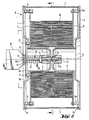
- the housing G of the cassette shown is extremely simple. It consists essentially of only three parts, namely two practically identical end plates 1 and 2 and a circumferential jacket 3, which is contained in circumferential grooves 1a and 2a of the end plates 1 and 2.
- the two end plates 1 and 2 each have an inwardly projecting protuberance in the form of a hollow cylindrical pin 4 or 5. These two pins run coaxially and together form the bearing mandrel for the roll W of photographic strip material to be accommodated in the cassette.
- a guide plate 6 or 7 is arranged in parallel at a distance to guide the winding W at the end.
- the guide plate 6 is arranged in a fixed manner with respect to the end plate 2 via fixed spacer bolts 6a.
- the guide plate 7, on the other hand, is movable in the direction of the pin or bearing pin axis A, springs 8 attached to the associated end plate 1 ensure that the guide plate 7 always presses with a preselected pressure laterally against the winding W and thereby guides it exactly and in brakes required dimension.
- a single locking element in the form of a screw bolt 10 is provided, which runs coaxially with the cylindrical pins 4 and 5. It is rotatably mounted in a bearing bush 11 formed on the pin 4 and engages with its threaded end 10a in a threaded bore 12 provided on the pin 5.
- a lock nut 13 and a locking ring 14 limit the axial mobility of the screw bolt in the bearing bush 11.
- the bolt 10 protrudes on the side of the end plate 1 from the housing G and carries at its end 10 b a plate-shaped rotating member 15.
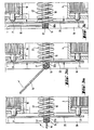
- This rotating member or this handle is provided with a cam member 16, the function of which is still to be explained, and on the outside End 10b of the bolt 10 is pivotally or foldably fastened about a folding axis 17 perpendicular thereto.
- the handle 15 lies parallel to the screw bolt 10 and can thus be actuated to rotate the latter (working position).
- FIG. 2 In one extreme position (FIG. 2), the handle 15 lies parallel to the screw bolt 10 and can thus be actuated to rotate the latter (working position). In the other extreme position (FIG.
- a dome plate 20 is provided, which is coupled to the guide plate 7 in the interior of the housing by pressure by means of spacer bolts 21 which pass through recesses in the end plate 1.
- the spacer bolts are only attached to the guide plate 7, but not to the coupling plate 20.
- the dome plate 20 rests, as shown in FIG. 2, due to the action of a compression spring 22 which surrounds the screw bolt 10 against the cam member 16, which is approximately square in cross section, on the handle 15, the spacer bolts 21 being out of contact with the dome plate 20 are. From the shape of the cam member 16 it can be seen that the dome plate 20 is furthest out in the two extreme positions of the handle (FIGS.
- the screw bolt 10 is loosened until it is out of engagement with the threaded bore 12 in the pin 5, and then the end plate 1 is removed. After insertion, the face plate 1 is put back on and the screw bolt 10 is tightened by means of the handle 15 until the housing is properly closed. When the handle 15 is then folded into the rest position, the aforementioned automatic alignment of the winding W then occurs.
- the jacket 3 of the cassette housing has in its upper part on one side a laterally projecting connection mouth 30, which is used for insertion into a corresponding connection opening in an automatic copying machine and thus for light-tight coupling to it.
- the mouth 30 contains a light-tight closure 31 which opens automatically when coupled to the copier.
- the mouth also contains coding means in the form of e.g. four small permanent magnets 32, which can be evaluated by reading means provided in the copying machine, preferably Hall sensors with associated electronics, and contain information about the width of the strip material currently in use.
- the use of small permanent magnets is a particularly simple and expedient type of coding which, above all, allows the coded information to be changed very easily and conveniently.
- the magnets are only loosely arranged in corresponding bores, and in order to change the information, a desired number of permanent magnets in a desired arrangement and desired polarization direction are simply inserted into these bores, the code representing the information being formed by the presence and the polarization direction of the permanent magnets .
- the code representing the information being formed by the presence and the polarization direction of the permanent magnets .
- Fig. 1 the coupling of the cassette to a copier is indicated. However, only one side wall 41 of the copying machine is shown with the insertion opening 42 for the connecting mouth 30 and a pair of transport rollers 43 and 44 for the strip material and an inlet slope 45 for actuating the light-tight closure indicated in the cassette mouth 30.
- the permanent magnets are symbolized by position 32.
- the cassette according to the invention described above is structurally extremely simple overall, extremely reliable in operation and very easy to handle.
Landscapes
- Physics & Mathematics (AREA)
- General Physics & Mathematics (AREA)
- Photographic Developing Apparatuses (AREA)
- Liquid Crystal (AREA)
Applications Claiming Priority (2)
| Application Number | Priority Date | Filing Date | Title |
|---|---|---|---|
| CH3290/85 | 1985-07-30 | ||
| CH329085 | 1985-07-30 |
Publications (2)
| Publication Number | Publication Date |
|---|---|
| EP0214928A1 EP0214928A1 (de) | 1987-03-18 |
| EP0214928B1 true EP0214928B1 (de) | 1989-03-15 |
Family
ID=4252785
Family Applications (1)
| Application Number | Title | Priority Date | Filing Date |
|---|---|---|---|
| EP86810336A Expired EP0214928B1 (de) | 1985-07-30 | 1986-07-24 | Kassette für fotografisches Bandmaterial |
Country Status (5)
| Country | Link |
|---|---|
| US (1) | US4741439A (da) |
| EP (1) | EP0214928B1 (da) |
| JP (1) | JPH0690449B2 (da) |
| DE (1) | DE3662472D1 (da) |
| DK (1) | DK162499C (da) |
Families Citing this family (23)
| Publication number | Priority date | Publication date | Assignee | Title |
|---|---|---|---|---|
| JPH01176649U (da) * | 1988-06-03 | 1989-12-15 | ||
| DE68926552T2 (de) * | 1988-08-05 | 1996-12-12 | Minolta Camera Kk | Filmkassette und Kamera für eine solche Kassette |
| US5271577A (en) * | 1989-07-04 | 1993-12-21 | Fuji Photo Film Co., Ltd. | Photographic film cassette |
| EP0406815B1 (en) * | 1989-07-04 | 1995-10-11 | Fuji Photo Film Co., Ltd. | Photographic film cassette |
| US5031853A (en) * | 1990-01-12 | 1991-07-16 | Eastman Kodak Company | Film-thrusting cassette |
| FR2658156B1 (fr) * | 1990-02-12 | 1992-06-12 | Kodak Pathe | Procede d'emballage, emballage et dispositif de manutention des produits en bandes. |
| DE9002409U1 (de) * | 1990-03-01 | 1990-05-03 | Du Pont de Nemours (Deutschland) GmbH, 6380 Bad Homburg | Lichtdichte Kassette |
| FR2663007A1 (fr) * | 1990-06-08 | 1991-12-13 | Kodak Pathe | Emballage de produits photographiques en bandes. |
| FR2663132B1 (fr) * | 1990-06-11 | 1993-05-28 | Kodak Pathe | Dispositif d'interfacage entre un poste debiteur et un poste recepteur de pellicule photographique. |
| EP0463997B1 (de) * | 1990-06-29 | 1995-01-18 | Gretag Imaging Ag | Kassette zum Aufwickeln von fotografischem Bandmaterial |
| JP2915619B2 (ja) * | 1991-05-13 | 1999-07-05 | 富士写真フイルム株式会社 | ペーパーマガジン装着装置及び方法 |
| US5161685A (en) * | 1991-07-31 | 1992-11-10 | Eastman Kodak Company | Flexible light-tight enclosure for photosensitive web roll |
| US5236143A (en) * | 1991-10-23 | 1993-08-17 | Dragon Bradley P | Intravenous tubing retractor apparatus |
| US5275347A (en) * | 1992-01-10 | 1994-01-04 | Management Graphics, Inc. | Autothread mechanism for strip material |
| EP0561438A1 (en) * | 1992-03-19 | 1993-09-22 | Agfa-Gevaert N.V. | A reloadable lighttight plastic cassette |
| CA2096054A1 (en) * | 1992-07-30 | 1994-01-31 | Alan D. Frazier | Rolled tissue dispenser |
| USD362454S (en) | 1993-09-30 | 1995-09-19 | Eastman Kodak Company | Mobile storage unit for photosensitive paper |
| US5390872A (en) * | 1993-09-30 | 1995-02-21 | Eastman Kodak Company | Package for rolls of photosensitive web |
| GB2327934A (en) * | 1997-07-31 | 1999-02-10 | Tony Sandland | Coil holder for variable coil thicknesses |
| US6238113B1 (en) * | 1999-09-30 | 2001-05-29 | Agfa Corporation | Media feed apparatus for imaging system |
| US6601790B2 (en) * | 2001-08-06 | 2003-08-05 | American Printing Components, Llc | Reusable cassette for photosensitive film |
| US7549602B2 (en) * | 2006-03-22 | 2009-06-23 | Hitachi Maxell, Ltd. | Tape cartridge |
| US9480371B2 (en) | 2011-05-02 | 2016-11-01 | Hardware Resources, Inc. | Self-securing roll holder and method |
Family Cites Families (16)
| Publication number | Priority date | Publication date | Assignee | Title |
|---|---|---|---|---|
| US2389495A (en) * | 1945-01-12 | 1945-11-20 | Miner Inc W H | Film holder |
| US3036207A (en) * | 1960-01-14 | 1962-05-22 | Mcphilben Mfg Co Inc | Lighting fixture |
| DE1258268B (de) * | 1962-06-14 | 1968-01-04 | Morningstar Corp | Filmspulenkassette |
| US3212729A (en) * | 1963-04-22 | 1965-10-19 | Gene M Putnam | Wire dispensing apparatus |
| US3353660A (en) * | 1965-08-19 | 1967-11-21 | Minnesota Mining & Mfg | Shipping container |
| BE754899A (fr) * | 1969-08-15 | 1971-01-18 | Cement & Concrete Ass | Procede et appareil pour la construction de routes rigides a surface texturee |
| US3612424A (en) * | 1970-03-27 | 1971-10-12 | Visual Graphics Corp | Storage and dispensing magazine for rolled strips of light sensitized material |
| DE2048684A1 (de) * | 1970-10-03 | 1972-04-06 | Norpnnt Ltd , Boston, Lincolnshire (Großbritannien) | Kassette zum Aufbewahren und Abziehen von Bandrollen |
| JPS5213929B2 (da) * | 1972-09-07 | 1977-04-18 | ||
| US4272035A (en) | 1980-04-14 | 1981-06-09 | Eastman Kodak Company | Light lock for roll dispensing container |
| US4403845A (en) * | 1980-12-09 | 1983-09-13 | Agfa-Gevaert N.V. | Cassette for holding and dispensing a roll of web material |
| JPS58133581U (ja) * | 1982-03-01 | 1983-09-08 | 松原 出 | 円環状製品のパツケ−ジ |
| DE3375377D1 (en) * | 1982-07-19 | 1988-02-25 | Horstmann Electronic | Magnetic coding arrangement for a workpiece |
| US4534519A (en) * | 1983-02-08 | 1985-08-13 | Pako Corporation | Photographic paper roll core holding device |
| EP0145813B1 (en) * | 1983-12-12 | 1988-02-03 | Agfa-Gevaert N.V. | Light-tight cassette |
| JPH0480374A (ja) * | 1990-07-23 | 1992-03-13 | Nippondenso Co Ltd | プリント配線板の製造方法 |
-
1986
- 1986-07-24 EP EP86810336A patent/EP0214928B1/de not_active Expired
- 1986-07-24 DE DE8686810336T patent/DE3662472D1/de not_active Expired
- 1986-07-29 US US06/890,274 patent/US4741439A/en not_active Expired - Lifetime
- 1986-07-29 DK DK359286A patent/DK162499C/da not_active IP Right Cessation
- 1986-07-30 JP JP61177863A patent/JPH0690449B2/ja not_active Expired - Lifetime
Also Published As
| Publication number | Publication date |
|---|---|
| DE3662472D1 (en) | 1989-04-20 |
| JPS6258243A (ja) | 1987-03-13 |
| DK359286A (da) | 1987-01-31 |
| JPH0690449B2 (ja) | 1994-11-14 |
| DK162499C (da) | 1992-06-01 |
| EP0214928A1 (de) | 1987-03-18 |
| DK359286D0 (da) | 1986-07-29 |
| DK162499B (da) | 1991-11-04 |
| US4741439A (en) | 1988-05-03 |
Similar Documents
| Publication | Publication Date | Title |
|---|---|---|
| EP0214928A1 (de) | Kassette für fotografisches Bandmaterial | |
| EP0037484B1 (de) | Vorrichtung zum Positionieren und Festhalten eines Teststreifens für optisch-medizinische Messungen | |
| DE3346025C2 (da) | ||
| EP0021388A1 (de) | Vorrichtung zum Abschneiden vertikaler Papierbahnen | |
| DE2553861A1 (de) | Photographische kamera mit wechselobjektiv | |
| DE2925837A1 (de) | Filmkassette mit einem fenster zum einbelichten von daten | |
| EP0270486A1 (de) | Tageslichtkassette | |
| DE2945840C2 (de) | Vorrichtung zur Zuführung des obersten Blattes von einem Blattstapel für ein Kopiergerät | |
| CH669468A5 (da) | ||
| EP0207059B1 (de) | Verschlussmechanik für Ordner | |
| DE1815850C3 (de) | Vorrichtung in oder an einem Kopiergerät mit räumlich getrennten Zuführtischen für Kopierpapier und Original K.K. Ricoh, Tokio | |
| DE2608504A1 (de) | Kassettenrecorder oder -spieler | |
| DE2532812A1 (de) | Kassettenhalterung fuer ein geraet zur magnetischen aufzeichnung und/oder wiedergabe von signalen | |
| DE3204652C2 (da) | ||
| DE3230633C2 (de) | Magnetschloß | |
| DE2651407C3 (de) | Rollenkassette | |
| DE69229157T2 (de) | Zuführungsmagazin für lichtempfindlichen Film in einem automatischen Filmbehandlungsapparat für Tageslicht | |
| DE2820136C2 (de) | Druckpresse | |
| DE1598918C3 (de) | Hubvorrichtung zum Heben und Senken von Probenträgern | |
| DE3615495C2 (de) | Antriebsvorrichtung für eine Auf- und Abwickelvorrichtung von Bahnmaterial mit Spulenkörpern | |
| DE3637246A1 (de) | Anordnung zum einsetzen und entnehmen einer kassette bei einer elektronischen standbildkamera | |
| DE3111964C2 (de) | Führungseinrichtung zum Führen einer Einwickelmaterialbahn bei einer Münzeneinwickelmaschine | |
| DE2504633C3 (de) | Kassettenspulen-Antriebsvorrichtung für eine Kassettenkamera | |
| DE2210753B2 (de) | Vorrichtung zum Verschließen von Behältern | |
| EP0463997A1 (de) | Kassette zum Aufwickeln von fotografischem Bandmaterial |
Legal Events
| Date | Code | Title | Description |
|---|---|---|---|
| PUAI | Public reference made under article 153(3) epc to a published international application that has entered the european phase |
Free format text: ORIGINAL CODE: 0009012 |
|
| 17P | Request for examination filed |
Effective date: 19860726 |
|
| AK | Designated contracting states |
Kind code of ref document: A1 Designated state(s): CH DE FR GB IT LI |
|
| 17Q | First examination report despatched |
Effective date: 19880222 |
|
| GRAA | (expected) grant |
Free format text: ORIGINAL CODE: 0009210 |
|
| AK | Designated contracting states |
Kind code of ref document: B1 Designated state(s): CH DE FR GB IT LI |
|
| REF | Corresponds to: |
Ref document number: 3662472 Country of ref document: DE Date of ref document: 19890420 |
|
| ET | Fr: translation filed | ||
| ITF | It: translation for a ep patent filed | ||
| GBT | Gb: translation of ep patent filed (gb section 77(6)(a)/1977) | ||
| PLBE | No opposition filed within time limit |
Free format text: ORIGINAL CODE: 0009261 |
|
| STAA | Information on the status of an ep patent application or granted ep patent |
Free format text: STATUS: NO OPPOSITION FILED WITHIN TIME LIMIT |
|
| 26N | No opposition filed | ||
| REG | Reference to a national code |
Ref country code: GB Ref legal event code: 727 |
|
| ITTA | It: last paid annual fee | ||
| REG | Reference to a national code |
Ref country code: CH Ref legal event code: PVP Owner name: QUALEX INC. |
|
| REG | Reference to a national code |
Ref country code: CH Ref legal event code: PUE Owner name: GRETAG AKTIENGESELLSCHAFT TRANSFER- GRETAG IMAGING |
|
| REG | Reference to a national code |
Ref country code: GB Ref legal event code: 732E |
|
| REG | Reference to a national code |
Ref country code: FR Ref legal event code: TP |
|
| PGFP | Annual fee paid to national office [announced via postgrant information from national office to epo] |
Ref country code: GB Payment date: 20000614 Year of fee payment: 15 |
|
| PGFP | Annual fee paid to national office [announced via postgrant information from national office to epo] |
Ref country code: CH Payment date: 20000616 Year of fee payment: 15 |
|
| PGFP | Annual fee paid to national office [announced via postgrant information from national office to epo] |
Ref country code: FR Payment date: 20000629 Year of fee payment: 15 Ref country code: DE Payment date: 20000629 Year of fee payment: 15 |
|
| PG25 | Lapsed in a contracting state [announced via postgrant information from national office to epo] |
Ref country code: GB Free format text: LAPSE BECAUSE OF NON-PAYMENT OF DUE FEES Effective date: 20010724 |
|
| PG25 | Lapsed in a contracting state [announced via postgrant information from national office to epo] |
Ref country code: LI Free format text: LAPSE BECAUSE OF NON-PAYMENT OF DUE FEES Effective date: 20010731 Ref country code: CH Free format text: LAPSE BECAUSE OF NON-PAYMENT OF DUE FEES Effective date: 20010731 |
|
| GBPC | Gb: european patent ceased through non-payment of renewal fee |
Effective date: 20010724 |
|
| REG | Reference to a national code |
Ref country code: CH Ref legal event code: PL |
|
| PG25 | Lapsed in a contracting state [announced via postgrant information from national office to epo] |
Ref country code: FR Free format text: LAPSE BECAUSE OF NON-PAYMENT OF DUE FEES Effective date: 20020329 |
|
| PG25 | Lapsed in a contracting state [announced via postgrant information from national office to epo] |
Ref country code: DE Free format text: LAPSE BECAUSE OF NON-PAYMENT OF DUE FEES Effective date: 20020501 |
|
| REG | Reference to a national code |
Ref country code: FR Ref legal event code: ST |
|
| PG25 | Lapsed in a contracting state [announced via postgrant information from national office to epo] |
Ref country code: IT Free format text: LAPSE BECAUSE OF NON-PAYMENT OF DUE FEES;WARNING: LAPSES OF ITALIAN PATENTS WITH EFFECTIVE DATE BEFORE 2007 MAY HAVE OCCURRED AT ANY TIME BEFORE 2007. THE CORRECT EFFECTIVE DATE MAY BE DIFFERENT FROM THE ONE RECORDED. Effective date: 20050724 |