EP0215219A2 - Aménagement de refroidissement pour moteurs à combustion interne avec un ventilateur déclenchable - Google Patents
Aménagement de refroidissement pour moteurs à combustion interne avec un ventilateur déclenchable Download PDFInfo
- Publication number
- EP0215219A2 EP0215219A2 EP86109166A EP86109166A EP0215219A2 EP 0215219 A2 EP0215219 A2 EP 0215219A2 EP 86109166 A EP86109166 A EP 86109166A EP 86109166 A EP86109166 A EP 86109166A EP 0215219 A2 EP0215219 A2 EP 0215219A2
- Authority
- EP
- European Patent Office
- Prior art keywords
- cooling system
- fan blower
- switch
- internal combustion
- combustion engine
- Prior art date
- Legal status (The legal status is an assumption and is not a legal conclusion. Google has not performed a legal analysis and makes no representation as to the accuracy of the status listed.)
- Granted
Links
Images


Classifications
-
- F—MECHANICAL ENGINEERING; LIGHTING; HEATING; WEAPONS; BLASTING
- F01—MACHINES OR ENGINES IN GENERAL; ENGINE PLANTS IN GENERAL; STEAM ENGINES
- F01P—COOLING OF MACHINES OR ENGINES IN GENERAL; COOLING OF INTERNAL-COMBUSTION ENGINES
- F01P11/00—Component parts, details, or accessories not provided for in, or of interest apart from, groups F01P1/00 - F01P9/00
- F01P11/14—Indicating devices; Other safety devices
-
- B—PERFORMING OPERATIONS; TRANSPORTING
- B60—VEHICLES IN GENERAL
- B60K—ARRANGEMENT OR MOUNTING OF PROPULSION UNITS OR OF TRANSMISSIONS IN VEHICLES; ARRANGEMENT OR MOUNTING OF PLURAL DIVERSE PRIME-MOVERS IN VEHICLES; AUXILIARY DRIVES FOR VEHICLES; INSTRUMENTATION OR DASHBOARDS FOR VEHICLES; ARRANGEMENTS IN CONNECTION WITH COOLING, AIR INTAKE, GAS EXHAUST OR FUEL SUPPLY OF PROPULSION UNITS IN VEHICLES
- B60K11/00—Arrangement in connection with cooling of propulsion units
-
- F—MECHANICAL ENGINEERING; LIGHTING; HEATING; WEAPONS; BLASTING
- F01—MACHINES OR ENGINES IN GENERAL; ENGINE PLANTS IN GENERAL; STEAM ENGINES
- F01P—COOLING OF MACHINES OR ENGINES IN GENERAL; COOLING OF INTERNAL-COMBUSTION ENGINES
- F01P7/00—Controlling of coolant flow
- F01P7/02—Controlling of coolant flow the coolant being cooling-air
- F01P7/08—Controlling of coolant flow the coolant being cooling-air by cutting in or out of pumps
-
- Y—GENERAL TAGGING OF NEW TECHNOLOGICAL DEVELOPMENTS; GENERAL TAGGING OF CROSS-SECTIONAL TECHNOLOGIES SPANNING OVER SEVERAL SECTIONS OF THE IPC; TECHNICAL SUBJECTS COVERED BY FORMER USPC CROSS-REFERENCE ART COLLECTIONS [XRACs] AND DIGESTS
- Y10—TECHNICAL SUBJECTS COVERED BY FORMER USPC
- Y10S—TECHNICAL SUBJECTS COVERED BY FORMER USPC CROSS-REFERENCE ART COLLECTIONS [XRACs] AND DIGESTS
- Y10S292/00—Closure fasteners
- Y10S292/14—Hood latches
-
- Y—GENERAL TAGGING OF NEW TECHNOLOGICAL DEVELOPMENTS; GENERAL TAGGING OF CROSS-SECTIONAL TECHNOLOGIES SPANNING OVER SEVERAL SECTIONS OF THE IPC; TECHNICAL SUBJECTS COVERED BY FORMER USPC CROSS-REFERENCE ART COLLECTIONS [XRACs] AND DIGESTS
- Y10—TECHNICAL SUBJECTS COVERED BY FORMER USPC
- Y10T—TECHNICAL SUBJECTS COVERED BY FORMER US CLASSIFICATION
- Y10T70/00—Locks
- Y10T70/50—Special application
- Y10T70/5889—For automotive vehicles
- Y10T70/5903—Hood
- Y10T70/5907—With switch
Definitions
- the invention relates to a cooling system for internal combustion engines according to the preamble of the main claim.
- US Pat. No. 2,756,085 also discloses a locking mechanism for vehicle bonnets, in which the hood's closed position is monitored by means of a switch.
- the signal circuit connected to the switch only serves to warn a driver of an incompletely closed bonnet when starting or while driving.
- the advantages of the invention are primarily to be seen in the fact that a cooling system for internal combustion engines with switchable fan blower is created, which helps to avoid injuries to parts of the body of a maintenance person without noticeably disrupting the operation of the internal combustion engine and its cooling system.
- the additional measures necessary to achieve this goal are characterized by little effort, are inexpensive to manufacture and are also suitable for retrofitting existing vehicles.
- Fig. 1, 1 shows a motor vehicle, in the front structure or engine compartment 2, an internal combustion engine 3 is arranged. This is connected via coolant lines 4, 5 to a liquid cooler 6, which is acted upon by airflow cooling air via a body opening 7 on a car front 8 and a cooling air duct 9.
- the Liquid cooler 6 or the internal combustion engine 3 are forcibly cooled via a fan blower 10 driven by an electric motor if a temperature in the cooling system and / or the internal combustion engine exceeds a specific limit value.
- This forced cooling is also increasingly used in modern motor vehicles when - after the internal combustion engine has been switched off due to the residual heat stored in it - the internal combustion engine compartment 2 heats up too much. In this way it can be prevented that - not shown - fuel lines, which are laid in the area of an intake manifold 11, are heated above the boiling point of the fuel; A vapor bubble formation in the fuel system leading to starting difficulties is thus reliably avoided.
- a switch (touch switch) 13 is arranged on a frame 12 in which a flap (bonnet) 12 'is mounted in the closed state.
- An arrangement area which has been found to be particularly favorable here is in a position of the frame 12 which is adjacent to a locking mechanism 14 and is remote from a pivot point 15 of the bonnet 12 '.
- the switch is not actuated when the bonnet 12 'is open and can either directly interrupt an energy or current supply to the fan blower or act on a control unit which influences the fan blower or emits a warning signal or switches off the internal combustion engine if necessary.
- the switch 13 can of course also be a proximity switch; Likewise, a tilt (mercury) switch can be used, which is attached to the hood 12 'and opens its contacts in their open position.
- FIG. 2 shows how an electric motor 16 for driving the fan blower 10 driven by an electric motor is connected to the touch switch 13.
- the electric motor 16 has one pole against a vehicle mass 17 and is connected with its other pole via a normally open contact 18 of a thermal switch 19 monitoring a motor temperature and a normally open contact 20 of the touch switch 13 to a positive pole (+) of a vehicle battery 21, the negative pole ( -) is also due to vehicle mass 17.
- the touch switch 13 is actuated when the bonnet 12 is closed, so that the closer 20 closes the circuit between the battery 21 and the thermal switch 19.
- the fan blower 10 can thus be controlled depending on the thermal switch 19. If, on the other hand, the hood 12 'is opened, the closer 20 separates the electric motor 16 of the fan blower 10 from the battery 21. The fan blower 10 can therefore no longer cause hand injuries to the maintenance personnel.
- FIG. 3 A somewhat more extensive version is shown in FIG. 3.
- the fan blower is switched by an electronic control unit 27 via an electronic or electromechanical relay 26;
- the relay 26 can of course also be contained in the control unit 27.
- the control unit 27 receives signals at its inputs 28, 29 and 30 from the touch switch 13, a temperature switch or temperature sensor 31 monitoring the engine temperature and the ignition switch 22. It is supplied with the necessary operating current via the terminals 32 and 33.
- the outputs 34, 35 and 36 are used to control the relay 26 and, depending on the equipment, a signal transmitter (warning light 37 and / or warning buzzer 38) which emits an optical / acoustic signal and a relay 39 for interrupting the ignition current and / or the fuel supply.
- the fan blower is switched on here by means of a normally open contact 40 operated by the relay 26, and the ignition current is interrupted by an opener 41 controlled by the relay 39.
- a further input 42 can also be provided on the control unit 27, which is operated by a manually operated push button switch 43 (with normally open contact) 44 against positive pole (+)) is influenced and. to be explained later.
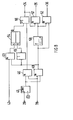
- FIGS. 4 to 8 show an internal connection of the control unit 27 between its inputs 28 to 30 and 42 and its outputs 34 to 36.
- the internal power supply has been omitted for the sake of clarity, as well as the Representation of common coupling modules at inputs and outputs; in a known manner, these coupling modules can include means for signal processing and / or electrical isolation as well as drivers and electronic or electromagnetic switching elements.
- Fig. 4 shows a basic configuration according to variant 1, which is essentially also included in all other variants.
- a temperature value of the temperature sensor 31 present at the input 29 is compared with a comparator 45 Compared reference value A; this emits a signal when the reference value is exceeded.
- This is switched by an AND gate 46 to the output 34 for controlling the fan blower only when a signal is present at the input 28, that is, the engine hood is closed.
- this circuit is expanded by a further AND gate 47 and an OR gate 48.
- the AND gate 47 also monitors whether the ignition (input 30) of the motor vehicle is switched on and only emits a signal if a signal from the comparator 45 is present at the same time.
- the outputs of the AND gates 46 and 47 are put together via the OR gate 48 on the output 34.
- Fig. 6 again contains the function of Fig. 4; this is extended by an AND gate 49, which is acted upon by the signal from the comparator 45 and the negated signal from the input 28 and, when the bonnet is open and the reference value at the comparator 45 is exceeded, the signal transmitters at the output 36, and at the output 35 the relay 39 for Switching off the ignition controls.
- this circuit is extended by a timing element 50, which delays the signal from the AND gate 49 by about 10 seconds via an OR gate 51 to the output 34, so that the fan starts delayed by this time.
- a further AND gate 52 in which the signal before the time delay element 50 and the negated signal at its output are applied to its inputs, the signal generators 37 and 38 are activated at the output 36.
- an AND gate 53 receives a signal from the key switch 43 via the input 42.
- the output of the AND gate 49 is applied to the second input of the AND gate 53. Its output is connected to a set input S of an RS flip-flop 54; whose reset input R is acted upon by the inverted output signal of the AND gate 49 by an inverter 55.
- the components 53 to 55 represent a latching circuit which can be set by means of the push-button switch when the comparator 45 is addressed and can be reset again when the comparator 45 falls below the reference value A.
- the relay 39 is activated via an AND gate 57 to interrupt the ignition.
- the AND gate 57 receives a negated signal from the OR gate 56 and a signal from the time delay element 50.
- control unit can also be constructed by means of a microcomputer system, which then takes over the functions of the logic modules, the comparator and the time delay element.
- an electromagnetic clutch of a fan driven by the internal combustion engine can also be controlled by one of the circuits according to FIGS. 2 to 8.
Landscapes
- Engineering & Computer Science (AREA)
- Chemical & Material Sciences (AREA)
- Combustion & Propulsion (AREA)
- Mechanical Engineering (AREA)
- General Engineering & Computer Science (AREA)
- Transportation (AREA)
- Cooling, Air Intake And Gas Exhaust, And Fuel Tank Arrangements In Propulsion Units (AREA)
Applications Claiming Priority (2)
| Application Number | Priority Date | Filing Date | Title |
|---|---|---|---|
| DE3533093 | 1985-09-17 | ||
| DE19853533093 DE3533093A1 (de) | 1985-09-17 | 1985-09-17 | Kuehlanlage fuer brennkraftmaschine mit einem zuschaltbaren lueftergeblaese |
Publications (3)
| Publication Number | Publication Date |
|---|---|
| EP0215219A2 true EP0215219A2 (fr) | 1987-03-25 |
| EP0215219A3 EP0215219A3 (en) | 1988-06-01 |
| EP0215219B1 EP0215219B1 (fr) | 1990-02-07 |
Family
ID=6281155
Family Applications (1)
| Application Number | Title | Priority Date | Filing Date |
|---|---|---|---|
| EP19860109166 Expired - Lifetime EP0215219B1 (fr) | 1985-09-17 | 1986-07-04 | Aménagement de refroidissement pour moteurs à combustion interne avec un ventilateur déclenchable |
Country Status (3)
| Country | Link |
|---|---|
| US (1) | US4748943A (fr) |
| EP (1) | EP0215219B1 (fr) |
| DE (2) | DE3533093A1 (fr) |
Cited By (1)
| Publication number | Priority date | Publication date | Assignee | Title |
|---|---|---|---|---|
| EP0644320A1 (fr) * | 1993-09-22 | 1995-03-22 | Bayerische Motoren Werke Aktiengesellschaft | Dispositif de refroidissement pour moteur à combustion interne refroidi par liquide d'un véhicule automobile |
Families Citing this family (10)
| Publication number | Priority date | Publication date | Assignee | Title |
|---|---|---|---|---|
| US5046554A (en) * | 1990-02-22 | 1991-09-10 | Calsonic International, Inc. | Cooling module |
| US5476138A (en) * | 1993-08-16 | 1995-12-19 | Calsonic International, Inc. | Motor vehicle with improved radiator and condenser mounting device |
| JP2007091062A (ja) * | 2005-09-29 | 2007-04-12 | Denso Corp | 車両の前端構造 |
| JP2007315619A (ja) * | 2006-05-23 | 2007-12-06 | Denso Corp | 熱交換器 |
| FR2950574B1 (fr) * | 2009-09-29 | 2012-03-23 | Valeo Systemes Thermiques | Bloc d'echange thermique pour vehicule automobile |
| US8708075B2 (en) * | 2012-01-16 | 2014-04-29 | Honda Motor Co., Ltd. | Front end structure for vehicle |
| US9228516B2 (en) * | 2012-09-04 | 2016-01-05 | GM Global Technology Operations LLC | Fuel pump prime activated by door sensor |
| DE102015210683A1 (de) | 2015-06-11 | 2016-12-15 | Röchling Automotive SE & Co. KG | Funktionsüberprüfbare Luftklappenvorrichtung |
| US10362715B2 (en) * | 2015-10-13 | 2019-07-23 | Lenovo Enterprise Solutions (Singapore) Pte. Ltd. | Automatically cooling computer system components for safe servicing |
| US10941704B2 (en) * | 2019-04-03 | 2021-03-09 | Ford Global Technologies, Llc | Systems and methods for controlling engine operation to support external electric loads |
Family Cites Families (9)
| Publication number | Priority date | Publication date | Assignee | Title |
|---|---|---|---|---|
| US2206094A (en) * | 1938-06-16 | 1940-07-02 | John W Hobbs Corp | Automobile engine light |
| US2576017A (en) * | 1949-02-09 | 1951-11-20 | Jeffrey John | Automobile hood position warning indicator |
| US2876856A (en) * | 1954-09-01 | 1959-03-10 | Sidney R Greene | Vehicle door-closed safety system |
| US2756085A (en) * | 1955-07-20 | 1956-07-24 | Frederick I Hochstadt | Barrier device for automobile hood locks |
| US3171392A (en) * | 1962-03-29 | 1965-03-02 | Magneti Marelli Spa | System and related apparatus for the cooling plant of internal combustion engines |
| US3611287A (en) * | 1970-04-24 | 1971-10-05 | Marc Hoff | Vehicle antitheft control and signal device |
| DE2645733A1 (de) * | 1976-10-09 | 1978-04-13 | Bayerische Motoren Werke Ag | Schaltanordnung fuer einen luefter- motor |
| JPS5825617U (ja) * | 1981-08-12 | 1983-02-18 | 日産自動車株式会社 | 車両のエンジンル−ム内冷却装置 |
| DE3445878A1 (de) * | 1984-12-15 | 1986-07-10 | Audi AG, 8070 Ingolstadt | Kraftfahrzeug mit thermostatgeschaltetem elektroluefter |
-
1985
- 1985-09-17 DE DE19853533093 patent/DE3533093A1/de not_active Withdrawn
-
1986
- 1986-07-04 DE DE8686109166T patent/DE3668942D1/de not_active Expired - Lifetime
- 1986-07-04 EP EP19860109166 patent/EP0215219B1/fr not_active Expired - Lifetime
- 1986-09-17 US US06/908,287 patent/US4748943A/en not_active Expired - Fee Related
Cited By (1)
| Publication number | Priority date | Publication date | Assignee | Title |
|---|---|---|---|---|
| EP0644320A1 (fr) * | 1993-09-22 | 1995-03-22 | Bayerische Motoren Werke Aktiengesellschaft | Dispositif de refroidissement pour moteur à combustion interne refroidi par liquide d'un véhicule automobile |
Also Published As
| Publication number | Publication date |
|---|---|
| DE3668942D1 (de) | 1990-03-15 |
| DE3533093A1 (de) | 1987-03-19 |
| EP0215219B1 (fr) | 1990-02-07 |
| EP0215219A3 (en) | 1988-06-01 |
| US4748943A (en) | 1988-06-07 |
Similar Documents
| Publication | Publication Date | Title |
|---|---|---|
| EP0215219B1 (fr) | Aménagement de refroidissement pour moteurs à combustion interne avec un ventilateur déclenchable | |
| DE3229003C2 (de) | Kühleinrichtung für den Motorraum eines Fahrzeugs | |
| EP1144224B1 (fr) | Reseau de bord a batterie, avec coupe-circuit de securite | |
| DE4139469A1 (de) | Elektrische stromquelle fuer elektrofahrzeuge | |
| DE3638131A1 (de) | Kuehlsystem einer wassergekuehlten fahrzeug-brennkraftmaschine | |
| DE102006027828B4 (de) | Motorsteuervorrichtung | |
| DE3534500C2 (fr) | ||
| EP0696524B1 (fr) | ContrÔle de prise de force | |
| DE60203810T2 (de) | Steuerung für eine Luftverteilungs- und Behandlungsanlage für Fahrzeuge | |
| DE4106205A1 (de) | Steuervorrichtung fuer ein fahrzeug zur steuerung einer darin angebrachten einrichtung | |
| DE2546076C2 (de) | Regelanordnung für Verbrennungsmotoren mit einer über einen Einschalter einschaltbaren Drehzahl-Regeleinrichtung | |
| DE3048989C2 (fr) | ||
| DE4415752A1 (de) | Diebstahlsicherungseinrichtung für Fahrzeuge | |
| DE20304546U1 (de) | Elektrische Kfz-Heizung | |
| DE69615718T2 (de) | Sicherheitstrennungsschalter zur automatischen Trennung elektrischer Lasten in Kraftfahrzeugen oder dergleichen | |
| DE2519902A1 (de) | Kraftfahrzeug-scheibenwaschanlage | |
| DE102013213929A1 (de) | Bordnetzsystem für ein Kraftfahrzeug | |
| DE2949457C2 (de) | Verzögerungsschaltung für eine Innenraumbeleuchtung eines Kraftfahrzeugs | |
| EP4489984A1 (fr) | Véhicule automobile, en particulier véhicule automobile électrique ou véhicule automobile hybride | |
| EP4321719B1 (fr) | Entraînement automatique pour un battant de porte | |
| DE69811190T2 (de) | Regelvorrichtung für Kraftfahrzeuganlasser | |
| DE10336953A1 (de) | Vorrichtung zum Schutz eines Gebläsemotors vor Überlastung | |
| DE3519003C1 (de) | Nachlaufsteuerung eines Lüftermotors | |
| DE1266143B (de) | Schalteinrichtung fuer Stellmotoren in Kraftfahrzeugen | |
| DE2131250C2 (de) | Einbruch- und Diebstahlwarneinrichtung für Kraftfahrzeuge |
Legal Events
| Date | Code | Title | Description |
|---|---|---|---|
| PUAI | Public reference made under article 153(3) epc to a published international application that has entered the european phase |
Free format text: ORIGINAL CODE: 0009012 |
|
| AK | Designated contracting states |
Kind code of ref document: A2 Designated state(s): DE FR GB IT SE |
|
| PUAL | Search report despatched |
Free format text: ORIGINAL CODE: 0009013 |
|
| AK | Designated contracting states |
Kind code of ref document: A3 Designated state(s): DE FR GB IT SE |
|
| 17P | Request for examination filed |
Effective date: 19880423 |
|
| 17Q | First examination report despatched |
Effective date: 19881028 |
|
| ITF | It: translation for a ep patent filed | ||
| GRAA | (expected) grant |
Free format text: ORIGINAL CODE: 0009210 |
|
| AK | Designated contracting states |
Kind code of ref document: B1 Designated state(s): DE FR GB IT SE |
|
| REF | Corresponds to: |
Ref document number: 3668942 Country of ref document: DE Date of ref document: 19900315 |
|
| GBT | Gb: translation of ep patent filed (gb section 77(6)(a)/1977) | ||
| ET | Fr: translation filed | ||
| PLBE | No opposition filed within time limit |
Free format text: ORIGINAL CODE: 0009261 |
|
| STAA | Information on the status of an ep patent application or granted ep patent |
Free format text: STATUS: NO OPPOSITION FILED WITHIN TIME LIMIT |
|
| 26N | No opposition filed | ||
| PGFP | Annual fee paid to national office [announced via postgrant information from national office to epo] |
Ref country code: SE Payment date: 19910627 Year of fee payment: 6 Ref country code: FR Payment date: 19910627 Year of fee payment: 6 |
|
| PGFP | Annual fee paid to national office [announced via postgrant information from national office to epo] |
Ref country code: GB Payment date: 19910703 Year of fee payment: 6 |
|
| PGFP | Annual fee paid to national office [announced via postgrant information from national office to epo] |
Ref country code: DE Payment date: 19910710 Year of fee payment: 6 |
|
| ITTA | It: last paid annual fee | ||
| PG25 | Lapsed in a contracting state [announced via postgrant information from national office to epo] |
Ref country code: GB Effective date: 19920704 |
|
| PG25 | Lapsed in a contracting state [announced via postgrant information from national office to epo] |
Ref country code: SE Effective date: 19920705 |
|
| GBPC | Gb: european patent ceased through non-payment of renewal fee |
Effective date: 19920704 |
|
| PG25 | Lapsed in a contracting state [announced via postgrant information from national office to epo] |
Ref country code: FR Effective date: 19930331 |
|
| PG25 | Lapsed in a contracting state [announced via postgrant information from national office to epo] |
Ref country code: DE Effective date: 19930401 |
|
| REG | Reference to a national code |
Ref country code: FR Ref legal event code: ST |
|
| EUG | Se: european patent has lapsed |
Ref document number: 86109166.8 Effective date: 19930204 |
|
| PG25 | Lapsed in a contracting state [announced via postgrant information from national office to epo] |
Ref country code: IT Free format text: LAPSE BECAUSE OF NON-PAYMENT OF DUE FEES;WARNING: LAPSES OF ITALIAN PATENTS WITH EFFECTIVE DATE BEFORE 2007 MAY HAVE OCCURRED AT ANY TIME BEFORE 2007. THE CORRECT EFFECTIVE DATE MAY BE DIFFERENT FROM THE ONE RECORDED. Effective date: 20050704 |