EP0215228A2 - Dispositif de changement d'outils - Google Patents
Dispositif de changement d'outils Download PDFInfo
- Publication number
- EP0215228A2 EP0215228A2 EP86109686A EP86109686A EP0215228A2 EP 0215228 A2 EP0215228 A2 EP 0215228A2 EP 86109686 A EP86109686 A EP 86109686A EP 86109686 A EP86109686 A EP 86109686A EP 0215228 A2 EP0215228 A2 EP 0215228A2
- Authority
- EP
- European Patent Office
- Prior art keywords
- tool
- tools
- gripper
- workpiece
- clamping
- Prior art date
- Legal status (The legal status is an assumption and is not a legal conclusion. Google has not performed a legal analysis and makes no representation as to the accuracy of the status listed.)
- Withdrawn
Links
Images

Classifications
-
- B—PERFORMING OPERATIONS; TRANSPORTING
- B23—MACHINE TOOLS; METAL-WORKING NOT OTHERWISE PROVIDED FOR
- B23Q—DETAILS, COMPONENTS, OR ACCESSORIES FOR MACHINE TOOLS, e.g. ARRANGEMENTS FOR COPYING OR CONTROLLING; MACHINE TOOLS IN GENERAL CHARACTERISED BY THE CONSTRUCTION OF PARTICULAR DETAILS OR COMPONENTS; COMBINATIONS OR ASSOCIATIONS OF METAL-WORKING MACHINES, NOT DIRECTED TO A PARTICULAR RESULT
- B23Q7/00—Arrangements for handling work specially combined with or arranged in, or specially adapted for use in connection with, machine tools, e.g. for conveying, loading, positioning, discharging, sorting
- B23Q7/04—Arrangements for handling work specially combined with or arranged in, or specially adapted for use in connection with, machine tools, e.g. for conveying, loading, positioning, discharging, sorting by means of grippers
- B23Q7/046—Handling workpieces or tools
-
- Y—GENERAL TAGGING OF NEW TECHNOLOGICAL DEVELOPMENTS; GENERAL TAGGING OF CROSS-SECTIONAL TECHNOLOGIES SPANNING OVER SEVERAL SECTIONS OF THE IPC; TECHNICAL SUBJECTS COVERED BY FORMER USPC CROSS-REFERENCE ART COLLECTIONS [XRACs] AND DIGESTS
- Y10—TECHNICAL SUBJECTS COVERED BY FORMER USPC
- Y10S—TECHNICAL SUBJECTS COVERED BY FORMER USPC CROSS-REFERENCE ART COLLECTIONS [XRACs] AND DIGESTS
- Y10S279/00—Chucks or sockets
- Y10S279/90—Adapted for automatic tool changer
-
- Y—GENERAL TAGGING OF NEW TECHNOLOGICAL DEVELOPMENTS; GENERAL TAGGING OF CROSS-SECTIONAL TECHNOLOGIES SPANNING OVER SEVERAL SECTIONS OF THE IPC; TECHNICAL SUBJECTS COVERED BY FORMER USPC CROSS-REFERENCE ART COLLECTIONS [XRACs] AND DIGESTS
- Y10—TECHNICAL SUBJECTS COVERED BY FORMER USPC
- Y10T—TECHNICAL SUBJECTS COVERED BY FORMER US CLASSIFICATION
- Y10T483/00—Tool changing
- Y10T483/16—Tool changing with means to transfer work
-
- Y—GENERAL TAGGING OF NEW TECHNOLOGICAL DEVELOPMENTS; GENERAL TAGGING OF CROSS-SECTIONAL TECHNOLOGIES SPANNING OVER SEVERAL SECTIONS OF THE IPC; TECHNICAL SUBJECTS COVERED BY FORMER USPC CROSS-REFERENCE ART COLLECTIONS [XRACs] AND DIGESTS
- Y10—TECHNICAL SUBJECTS COVERED BY FORMER USPC
- Y10T—TECHNICAL SUBJECTS COVERED BY FORMER US CLASSIFICATION
- Y10T483/00—Tool changing
- Y10T483/17—Tool changing including machine tool or component
- Y10T483/1702—Rotating work machine tool [e.g., screw machine, lathe, etc.]
- Y10T483/1714—Tool changer between tool support and matrix
- Y10T483/1719—Tool support comprises turret
- Y10T483/1721—Linearly moveable tool changer
-
- Y—GENERAL TAGGING OF NEW TECHNOLOGICAL DEVELOPMENTS; GENERAL TAGGING OF CROSS-SECTIONAL TECHNOLOGIES SPANNING OVER SEVERAL SECTIONS OF THE IPC; TECHNICAL SUBJECTS COVERED BY FORMER USPC CROSS-REFERENCE ART COLLECTIONS [XRACs] AND DIGESTS
- Y10—TECHNICAL SUBJECTS COVERED BY FORMER USPC
- Y10T—TECHNICAL SUBJECTS COVERED BY FORMER US CLASSIFICATION
- Y10T82/00—Turning
- Y10T82/25—Lathe
- Y10T82/2585—Tool rest
- Y10T82/2587—Turret type holder [e.g., multiple tools, etc.]
Definitions
- the invention relates to a device for changing tools into the tool holders of two cross-slides of a machine tool arranged independently on a cross slide that can be moved in a plane inclined to the horizontal, the tool holders of which run parallel to the workpiece spindle axis of the machine tool.
- a machine is equipped with a workpiece handling device, the workpiece gripper of which can be moved in a vertical plane parallel to the workpiece spindle axis.
- a tool changing device is known from DE - OS 31 18 594, which is used to change the tools of a tool turret of a machine tool which is not further described.
- the tool changing device uses a workpiece changing device which comprises a transport carriage which can be moved in the longitudinal direction of the machine tool, a carriage which can be moved vertically on the transport carriage and a gripper provided on the carriage.
- the gripper which is intended for workpiece handling, can also be equipped with pairs of grippers for tool change.
- the handling device has the advantage that it only has to be movable in two directions of movement.
- the publication refers to the tool change in just one turret. It is now desirable for a machine tool with two tool carriers to change the tool on both tool carriers in the same way, i. H. without increasing the effort.
- the invention is therefore based on the object of making it possible to change the tool with a handling device in a machine tool having two tool turrets which are arranged on a tool slide which can be moved independently in a plane inclined to the horizontal, and which can be moved only in a horizontal and a vertical axis.
- the difficulty to be overcome was that, in the case of tool carriers arranged on an inclined plane, the tool changing positions of corresponding tool holders in the tool turret cannot be reached by the handling device. Moving tool holders with the same switching angle of the tool turret into a common changing plane is impossible because of the large travel distances required for this and would lead to collisions between the tool carriers.
- the safety of the tool transport and change is increased if the tools or tool holders have elements that ensure the unchangeable position of the tools or tool holder.
- Such an element can be the flat clamping surface on the tool holder.
- the same tools can be used for loading both tool turrets if the elements or clamping surfaces determining the position in the gripper are offset offset 90 degrees.
- the tools or the tool holders are given a stable position when the gripping fingers have V-shaped gripping surfaces in cross section and the tool holders have V-shaped counter-surfaces.
- the risk of collision when inserting the tool holder, in particular in the upper tool turret with adjacent tools, is reduced by a fixed, cranked clamping finger.
- the straight clamping surface must be arranged on this clamping finger.
- the gripping surface can be slightly inclined with respect to the vertical direction of movement of the tool gripper.
- the tools are stored in a magazine in the position in which they must be used in the respective tool turret.
- the tool magazine can be divided into two areas, each area being assigned to the tools of a turret.
- An associated tool store can also be provided for each tool turret, so that the number of tools increases. In any case, at least as many tools should be arranged in the magazine as can be accommodated in one or in two tool turrets.
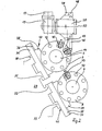
- FIG. 1 shows a workpiece handling device 2 that protrudes beyond a machine tool 1.
- the machine frame 4 carries on a slant bed two tool turrets 5, 6, each with a turret disk 7, 8, in which tools 9, 10 are accommodated.
- the turret disks are switched about axes parallel to the workpiece spindle axis 11.
- a chuck 12 for receiving the workpiece to be machined is fastened to the workpiece spindle (not shown).
- the workpiece handling device 2 consists of a crossbar 15 resting on supports 13, 14, on which a carriage 16 is mounted so as to be movable in the direction of the workpiece spindle axis 11.
- a carriage 16 In the carriage 16, two guide tubes 17 are mounted, which can be moved vertically by a drive motor 18.
- the guide tubes 17 pass at their lower end into the support arm 19, on which the gripper carrier 20 is rotatably attached.
- It is a double gripper with tool grippers 21, 22 arranged on the two opposite sides of the gripper carrier 20.
- the tool grippers 21, 22 are detachably attached to the gripper carrier and can be exchanged automatically for workpiece grippers or clamping jaw pallet grippers.
- a workpiece pallet transport system 25 is arranged in the travel area of the support arm 19, which pallet 26 optionally equipped with workpieces or tools 27, 23 is moved step by step under the support arm 13 in such a way that the workpieces or tools 27, 23 move from the one on the support arm 19 attached gripper can be picked up.
- the machine tool bed 29 carries four guideways 30, 31, 32, 33 on which bed slides 34, 35 are mounted so as to be movable in the spindle axis direction 11.
- the bed Carriages 34, 35 in turn carry guideways 36, 37 on which cross slides 38, 39 can be moved perpendicular to the direction of movement of the bed slides 34, 35.
- Face slide 38 and bed slide 34 form a cross slide 40 which carries the upper tool turret 5, while the lower cross slide 41, formed from the face slide 39 and the bed slide 35, carries the lower tool turret 6.
- Turret disks 7, 8 are rotatably attached to the tool turrets 5, 6 and have tool holders 42 in the form of bores running parallel to the switching axes of the tool turrets 5, 6.
- standardized tool holders 43, 44, 45 with cylindrical, toothed tool holder shafts can be inserted into the tool holder 42.
- the tool holders are provided with the same clamping surfaces, on which they can be held non-rotatably by the clamping fingers 46, 47 or 48, 49.
- the clamping fingers 46, 47 and 48, 49 belong to the tool grippers 21, 22 which can be pivoted about a horizontal switching axis 50 with respect to the support arm 19 and which are detachably fastened to the gripper carrier 20.
- the clamping fingers 47, 49 on the machine tool side are immovable with respect to the tool gripper 21, 22, while the opposing clamping fingers 46, 43 execute the clamping movement as a pivoting movement.
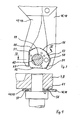
- FIG. 3 shows the clamping surfaces of the tool holders 43, 44, 45 already mentioned in more detail. They consist of two longer, straight, V-shaped grooves 51, 52 offset by 90 degrees, each of which is opposed by two shorter, V-shaped grooves 53, 54 and 55, 56 arranged at an angle. V-shaped webs 57, 58 of the clamping fingers 46, 47 and 48.49 engage in the V-shaped grooves 51-56.
- the section through the tool holder shaft 59 shows the toothing 60 provided for clamping in the tool turret disk 7, 8, which defines the angular position in relation to the tool turret disk 7, 8. Since the left clamping fingers 47, 49 do not swing out, the webs 57 are arranged at an angle to the vertical.
- V-shaped webs 57, 53 of the clamping fingers 46, 47, 43, 49 are visible.
- the associated V-shaped grooves 51, 53 are arranged in an adapter plate 61, which is screwed to a tool holder 43, 44, 45.
- the tool holder shaft 59 is seated in the tool holder 42 of a turret disk 7.3.
Landscapes
- Engineering & Computer Science (AREA)
- Mechanical Engineering (AREA)
- Automatic Tool Replacement In Machine Tools (AREA)
- Turning (AREA)
Applications Claiming Priority (2)
| Application Number | Priority Date | Filing Date | Title |
|---|---|---|---|
| DE19853532924 DE3532924A1 (de) | 1985-09-14 | 1985-09-14 | Werkzeugwechselvorrichtung |
| DE3532924 | 1985-09-14 |
Publications (2)
| Publication Number | Publication Date |
|---|---|
| EP0215228A2 true EP0215228A2 (fr) | 1987-03-25 |
| EP0215228A3 EP0215228A3 (fr) | 1988-09-07 |
Family
ID=6281036
Family Applications (1)
| Application Number | Title | Priority Date | Filing Date |
|---|---|---|---|
| EP86109686A Withdrawn EP0215228A3 (fr) | 1985-09-14 | 1986-07-15 | Dispositif de changement d'outils |
Country Status (3)
| Country | Link |
|---|---|
| US (1) | US4729159A (fr) |
| EP (1) | EP0215228A3 (fr) |
| DE (1) | DE3532924A1 (fr) |
Cited By (1)
| Publication number | Priority date | Publication date | Assignee | Title |
|---|---|---|---|---|
| US20200215621A1 (en) * | 2019-01-08 | 2020-07-09 | Esa Eppinger Gmbh | Machine Tool |
Families Citing this family (7)
| Publication number | Priority date | Publication date | Assignee | Title |
|---|---|---|---|---|
| DE3727684A1 (de) * | 1987-08-19 | 1989-03-02 | Traub Ag | Anordnung zum wechseln von werkzeugen an einer drehmaschine |
| JPH07106564B2 (ja) * | 1989-10-02 | 1995-11-15 | 功 庄田 | 工作機のヘッドおよび工具交換装置 |
| US5121539A (en) * | 1991-07-17 | 1992-06-16 | Trumpf Gmbh & Company | Apparatus and method for cutting stacked sheet-like workpieces |
| FR2727885A1 (fr) * | 1994-12-09 | 1996-06-14 | Renault Automation | Machine-outil pour l'usinage de vilebrequins pour des moteurs a quatre cylindres en ligne, son procede de travail et chaine d'usinage integrant une telle machine-outil |
| DE19838635A1 (de) * | 1998-08-26 | 2000-03-02 | Drm Druckgus Gmbh | Fertigungskonzept für Drehteile |
| JP5026884B2 (ja) * | 2007-08-04 | 2012-09-19 | 株式会社森精機製作所 | 自動工具交換装置を有する工作機械 |
| TWI780772B (zh) * | 2021-06-16 | 2022-10-11 | 中傳科技股份有限公司 | 刀具與刀把的配對系統與配對方法 |
Family Cites Families (14)
| Publication number | Priority date | Publication date | Assignee | Title |
|---|---|---|---|---|
| DE1502031B2 (de) * | 1965-09-29 | 1975-07-24 | Gildemeister Ag, 4800 Bielefeld | Mehrspindel-Drehautomat |
| CH544616A (de) * | 1971-10-01 | 1973-11-30 | Oerlikon Buehrle Ag | Werkzeugwechselvorrichtung |
| JPS501480A (fr) * | 1973-04-06 | 1975-01-09 | ||
| GB1444301A (en) * | 1974-06-12 | 1976-07-28 | Churchill Charles Ltd | Turning machines |
| DE2651096A1 (de) * | 1976-11-09 | 1978-05-18 | Heyligenstaedt & Co | Werkzeugwechseleinrichtung an drehmaschinen |
| GB2073625B (en) * | 1980-04-15 | 1983-06-29 | Devlieg Machine Co Ltd | Tool-change device for a machine tool |
| SE435833B (sv) * | 1980-05-13 | 1984-10-22 | Smt Machine Co Ab | Verktygsbytesanordning |
| DE3143409A1 (de) * | 1981-11-02 | 1983-05-11 | Heyligenstaedt & Co, Werkzeugmaschinenfabrik Gmbh, 6300 Giessen | Drehmaschine |
| DE3206547A1 (de) * | 1982-02-24 | 1983-09-01 | J. E. Reinecker Maschinenbau GmbH & Co KG, 7900 Ulm | Schleifmaschine mit einem steuerbaren werkstueckhandhabungssystem |
| SU1074700A1 (ru) * | 1982-08-09 | 1984-02-23 | Ульяновское Головное Специальное Конструкторское Бюро Тяжелых И Фрезерных Станков | Устройство дл автоматической смены инструмента |
| US4577389A (en) * | 1983-04-19 | 1986-03-25 | Textron, Inc. | Automatic tool changer |
| DE3320693A1 (de) * | 1983-06-08 | 1984-12-13 | Traub Gmbh, 7313 Reichenbach | Werkzeughalter fuer werkzeugmaschinen |
| AT378710B (de) * | 1983-12-01 | 1985-09-25 | Voest Alpine Ag | Drehmaschine |
| DE3427245C2 (de) * | 1984-07-24 | 1986-07-17 | Maschinenfabrik Diedesheim GmbH, 6950 Mosbach | Werkzeugmaschine |
-
1985
- 1985-09-14 DE DE19853532924 patent/DE3532924A1/de active Granted
-
1986
- 1986-07-15 EP EP86109686A patent/EP0215228A3/fr not_active Withdrawn
- 1986-09-11 US US06/906,922 patent/US4729159A/en not_active Expired - Fee Related
Cited By (2)
| Publication number | Priority date | Publication date | Assignee | Title |
|---|---|---|---|---|
| US20200215621A1 (en) * | 2019-01-08 | 2020-07-09 | Esa Eppinger Gmbh | Machine Tool |
| US11759903B2 (en) * | 2019-01-08 | 2023-09-19 | Esa Eppinger Gmbh | Machine tool |
Also Published As
| Publication number | Publication date |
|---|---|
| US4729159A (en) | 1988-03-08 |
| EP0215228A3 (fr) | 1988-09-07 |
| DE3532924C2 (fr) | 1991-09-26 |
| DE3532924A1 (de) | 1987-03-26 |
Similar Documents
| Publication | Publication Date | Title |
|---|---|---|
| DE2739534C2 (de) | Werkzeugwechselvorrichtung | |
| DE19521846B4 (de) | Numerisch gesteuerte Bearbeitungsmaschine | |
| DE3427245C2 (de) | Werkzeugmaschine | |
| DE19510498C2 (de) | Werkzeugwechseleinrichtung mit einem aus mehreren Teilspeichern bestehenden Werkzeuspeicher | |
| DE2944540A1 (de) | Werkstueckwechselvorrichtung fuer werkzeugmaschinen | |
| EP0995539B1 (fr) | Dispositif d'usinage de pièces | |
| CH665586A5 (de) | Werkzeugmaschine. | |
| DE2904088C2 (de) | Be- und/oder Entladeeinrichtung für Werkzeugmaschinen, insbesondere Drehautomaten | |
| EP1413395A1 (fr) | Machine-outil | |
| DE3420719A1 (de) | Werkzeugmaschine mit zwei werkstueckspindeln | |
| EP0885686A1 (fr) | Centre d'usinage | |
| DE19904860C2 (de) | Vertikaldrehmaschine | |
| DE2526342B2 (de) | Werkzeugrevolverkopf für Drehmaschinen | |
| DE3803219C2 (fr) | ||
| DE3532924C2 (fr) | ||
| EP0239564A2 (fr) | Machine à tourner | |
| DE4435024C2 (de) | Bohr- und Fräsmaschine mit verfahrbarer Werkstückspannvorrichtung | |
| DE3206547A1 (de) | Schleifmaschine mit einem steuerbaren werkstueckhandhabungssystem | |
| EP0137117B1 (fr) | Dispositif changeur d'outils comprenant un appareil pour le transfert des têtes d'outils | |
| WO1981000688A1 (fr) | Machine-outil avec changement automatique de l'outil | |
| DE3530982A1 (de) | Zweispindlige, numerisch gesteuerte drehmaschine | |
| EP0129677A2 (fr) | Centre d'usinage pour travaux de fraisage et de perçage | |
| DE3043361C2 (de) | Automatische Palettenwechseleinrichtung für Werkzeugmaschinen | |
| EP0410044A1 (fr) | Tour avec trois broches porte-pièce | |
| EP0291570A2 (fr) | Machine-outil à broche verticale et dispositif de changement d'outil |
Legal Events
| Date | Code | Title | Description |
|---|---|---|---|
| PUAI | Public reference made under article 153(3) epc to a published international application that has entered the european phase |
Free format text: ORIGINAL CODE: 0009012 |
|
| AK | Designated contracting states |
Kind code of ref document: A2 Designated state(s): AT BE CH FR GB IT LI SE |
|
| PUAL | Search report despatched |
Free format text: ORIGINAL CODE: 0009013 |
|
| AK | Designated contracting states |
Kind code of ref document: A3 Designated state(s): AT BE CH FR GB IT LI SE |
|
| 17P | Request for examination filed |
Effective date: 19880823 |
|
| 17Q | First examination report despatched |
Effective date: 19891206 |
|
| STAA | Information on the status of an ep patent application or granted ep patent |
Free format text: STATUS: THE APPLICATION HAS BEEN WITHDRAWN |
|
| 18W | Application withdrawn |
Withdrawal date: 19900723 |
|
| R18W | Application withdrawn (corrected) |
Effective date: 19900723 |
|
| RIN1 | Information on inventor provided before grant (corrected) |
Inventor name: KUSKA, JOACHIM Inventor name: SCHAEFER, WOLFGANG Inventor name: HENNEBERG, HASSO |