EP0215441B1 - Petite machine électrique rotative - Google Patents
Petite machine électrique rotative Download PDFInfo
- Publication number
- EP0215441B1 EP0215441B1 EP86112526A EP86112526A EP0215441B1 EP 0215441 B1 EP0215441 B1 EP 0215441B1 EP 86112526 A EP86112526 A EP 86112526A EP 86112526 A EP86112526 A EP 86112526A EP 0215441 B1 EP0215441 B1 EP 0215441B1
- Authority
- EP
- European Patent Office
- Prior art keywords
- permanent magnet
- demagnetizing
- anisotropic
- magnetizing
- magnet
- Prior art date
- Legal status (The legal status is an assumption and is not a legal conclusion. Google has not performed a legal analysis and makes no representation as to the accuracy of the status listed.)
- Expired - Lifetime
Links
- 230000005415 magnetization Effects 0.000 claims description 12
- 230000001154 acute effect Effects 0.000 claims description 3
- 239000000696 magnetic material Substances 0.000 claims description 3
- 230000002093 peripheral effect Effects 0.000 claims description 3
- 230000004907 flux Effects 0.000 description 22
- 230000005347 demagnetization Effects 0.000 description 7
- 238000010586 diagram Methods 0.000 description 3
- 230000000694 effects Effects 0.000 description 3
- 230000005389 magnetism Effects 0.000 description 3
- XEEYBQQBJWHFJM-UHFFFAOYSA-N Iron Chemical compound [Fe] XEEYBQQBJWHFJM-UHFFFAOYSA-N 0.000 description 2
- 229910000859 α-Fe Inorganic materials 0.000 description 2
- 239000000853 adhesive Substances 0.000 description 1
- 230000001070 adhesive effect Effects 0.000 description 1
- 229910000828 alnico Inorganic materials 0.000 description 1
- 230000002146 bilateral effect Effects 0.000 description 1
- 239000002131 composite material Substances 0.000 description 1
- 238000000748 compression moulding Methods 0.000 description 1
- 238000010276 construction Methods 0.000 description 1
- 230000001419 dependent effect Effects 0.000 description 1
- 229910052742 iron Inorganic materials 0.000 description 1
- 238000000034 method Methods 0.000 description 1
- 230000007935 neutral effect Effects 0.000 description 1
- 230000035699 permeability Effects 0.000 description 1
- 229910052761 rare earth metal Inorganic materials 0.000 description 1
- 150000002910 rare earth metals Chemical class 0.000 description 1
- 239000013598 vector Substances 0.000 description 1
- 238000004804 winding Methods 0.000 description 1
Images

Classifications
-
- H—ELECTRICITY
- H02—GENERATION; CONVERSION OR DISTRIBUTION OF ELECTRIC POWER
- H02K—DYNAMO-ELECTRIC MACHINES
- H02K1/00—Details of the magnetic circuit
- H02K1/06—Details of the magnetic circuit characterised by the shape, form or construction
- H02K1/12—Stationary parts of the magnetic circuit
- H02K1/17—Stator cores with permanent magnets
-
- H—ELECTRICITY
- H02—GENERATION; CONVERSION OR DISTRIBUTION OF ELECTRIC POWER
- H02K—DYNAMO-ELECTRIC MACHINES
- H02K23/00—DC commutator motors or generators having mechanical commutator; Universal AC/DC commutator motors
- H02K23/02—DC commutator motors or generators having mechanical commutator; Universal AC/DC commutator motors characterised by arrangement for exciting
- H02K23/04—DC commutator motors or generators having mechanical commutator; Universal AC/DC commutator motors characterised by arrangement for exciting having permanent magnet excitation
-
- H—ELECTRICITY
- H02—GENERATION; CONVERSION OR DISTRIBUTION OF ELECTRIC POWER
- H02K—DYNAMO-ELECTRIC MACHINES
- H02K15/00—Processes or apparatus specially adapted for manufacturing, assembling, maintaining or repairing of dynamo-electric machines
- H02K15/02—Processes or apparatus specially adapted for manufacturing, assembling, maintaining or repairing of dynamo-electric machines of stator or rotor bodies
- H02K15/03—Processes or apparatus specially adapted for manufacturing, assembling, maintaining or repairing of dynamo-electric machines of stator or rotor bodies having permanent magnets
Definitions
- This invention relates generally to a miniature electric non-uniform magnetization rotating machine of the kind referred to in. the precharacterizing portion of patent claim 1.
- a miniature electric rotating machine is known from FR-A-2 171 070.
- Permanent magnet field system DC machines using a permanent magnet for poles are known in the art.
- the permanent magnet used for DC machines of this type has generally an arc shape and the magnet is an anisotropic magnet.
- the permanent magnet is magnetized by a magnetizer such as one that is disclosed in JP-A-43 167/1983 entitled "Magnetizer of Field System Aggregate" which was laid open on March 12, 1983.
- the magnet is magnetized in anisotropic directions substantially towards the center in a radial direction. Therefore, a problem occurs that when the magnetic flux of armature reaction due to an armature current acts, the permanent magnet disposed on a demagnetizing side is demagnetized. This means that the thickness of the permanent magnet must be incrased.
- FR-A-2 171 070 discloses different magnetizing vectors on the magnetizing side and on the demagnetizing side of the magnets, including right, acute and obtuse angles.
- the DC motor according to FR-A-2 171 070 forms a neutral zone in the air gap between the end surfaces of the two magnets, in which the flux is offset due to the armature reaction, in such a manner that the anisotropic directions of the magnet in the portions near the longitudinal flancs gradually change from one end surface to the other end surface.
- the thickness of the magnet of the DC motor according to FR-A-2 171 070 towards its radial direction is demanded to increase.
- the magnetizing direction at a zone having a slot is approximately straight from the N pole to the S pole as shown in the figures thereof.
- the direction is one passing the magnetic flux.
- the magnet of DE-A-1 613 319 is formed by a ring shape magnet.
- the arrangement according to the invention can offset the reaction magnetic flux due to an armature reaction in the proximity of the end portion on the demagnetizing side, so that the thickness of the permanent magnet for a field system for offsetting the armature reaction in the magnetizing direction can be reduced and eventually, the thickness of the permanent magnet for the field system can be reduced.
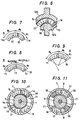
- Fig. 1 is a sectional view, in an axial direction, of a two-pole permanent magnet field system electric machine.
- a rotor consisting of a shaft 1, a commutator 2 and an armature formed by winding a widing 4 on an armature core 3 are supported by end brackets 6a, 6b on a fixing side through bearings 5a, 5b, respectively.
- These end brackets are fixed to a cylindrical yoke 7.
- Two permanent magnets 8 respectively having an arc shape are disposed equidistantly on the inner periphery of the yoke 7 and are fixed with an adhesive, or the like.
- Reference numeral 9 represents a brush, which is fixed to the bracket 6a through a brush holder 10.
- the permanent magnet 8 which constitutes the gist of the invention is a ferrite type anisotropic permanent magnet and has an arc shape.
- this permanent magnet 8 is produced in such a fshion that its anisotropic direction varies depending upon a peripheral position.
- the anisotropic direction of the permanent magnet extends towards the center axis of the armature core 3 from the portion e A on the magnetizing side where the armature reaction acts in the magnetizing direction to the portion es on the demagnetizing side from the center of magnetism 0-0' where the armature reaction acts in the demagnetizing direction, as shown in Fig. 3.
- the present invention is not limited to the above, in particular. Namely, the present invention embraces also the arrangement in which the magnetizing directions of the portions on the magnetizing and demagnetizing sides extend towards the center of the armature core such as the arrangement where the magnetizing directions are parallel to each other.
- the anisotropic direction is substantially at right angles to the line of the end portion 11 on the demagnetizing side.
- the anisotropic permanent magnet having these two directions can be produced by compression- molding a magnetic material, and causing a magnetic field to act upon the mold by use of a magnetizer such as shown in Fig. 6 so as to provide the magnet with anisotropy.
- the armature reaction takes place.
- the armature reaction electromotive force acts as the magnetizing force on the left side from the center of magnetism 0-0' of the permanent magnet and as the demagnetizing force, that is, in a direction which reduces the flux of the permanent magnet, on the right side from the center of magnetism 0-0'.
- the demagnetizing force acting upon the permanent magnet 8 is great at the end portion 11.
- the yoke consists of an external yoke 12a and an internal yoke 12b having a projection 13, and both of these yokes cover the permanent magnet 8.
- the projection 13 extends in a radial direction in such a manner as to cover the end portion 11 on the demagnetizing side of the permanent magnet 11.
- the semi-spherical portion i8 shown in Fig. 6 of the intemal yoke 12b may be made flat.
- the present invention deals with a two-pole machine by way of example, it can be applied to multiple-pole machines such as a four-pole or six- pole machine.
- the invention deals with the D.C. electric rotating machine by way of example, it can be applied similarly effectively to rotating machines so long as they use a permanent magnet.
- the embodiment described above uses the ferrite type permanent magnet by way of example, the effect of the invention remains the same so long as the permanent magnet is an anisotropic magnet such as a rare earth magnet, plastic magnet, rubber magnet, alnico magnet, or the like.
- the direction of anisotropy of the portion ec on the demagnetizing side of the permanent magnet 8 is substantially at right angles to the line on the end portion II on the demagnetizing side, the angle need not always be right angles but may be an acute or obtuse angle.
- the direction of anisotropy may be determined depending upon the incident direction of the reaction flux due to the armature reaction of a rotating machine of each type in order to obtain the maximum effect.
- the angle ec of the portion on the demagnetizing side of the permanent magnet 8 may be determined depending upon the model of the rotating machine while taking into consideration which of the generation flux quantity and demagnetization resistance is to be emphasized.
- the end portion 11 on the demagnetizing side of the permanent magnet 8 having the shapes such as shown in Figs. 7, 8 and 9 may be provided with anisotropy that offsets the reaction flux of the armature reaction of an electric rotating machine such as the rotating machine of the present invention.
- both end surfaces Ila are cut while in Fig. 8, both end portions II of the permanent magnet 8 for a bilateral rotating machine are cut in order to provide them with anisotropy, respectively.
- the gap length at both end portions of the permanent magnet 8 is expanded and the center of an outer diameter is different from that of an inner diameter.
- demagnetization resistance of the permanent magnet can be further improved by providing the magnet with anisotropy according to the present invention.
- Fig. II shows a permanent magnet field system D.C. rotating machine equipped with auxiliary poles, which has a construction wherein a field pole is constituted on the inner periphery of the yoke 7 by the permanent magnet 8 and auxiliary poles made of a magnetic material and acting upon the magnetization of the armature reaction.
- the effect of the present invention will remain the same if the anisotropy of the end portion II on the demagnetizing side of the permanent magnet 8 of this field pole is the same as that of the present invention.
- the end portion on the demagnetizing side of the high coercive force portion may be provided with anisotropy so as to offset the armature reaction as in the present invention.
- the present invention is not particularly limited thereto.
- the direction of anisotropy in the magnetizing direction of the end portion of the permanent magnet on the demagnetizing side is set in a direction which offsets the reaction flux, and the demagnetization resistance of the permanent magnet can be improved. Therefore, the thickness of the permanent magnet can be reduced as described already, and a compact, light-weight rotating machine can be produced economically.
- the magnetic flux leaks from the end portion on the demagnetizing side to the yoke at the time of non-load where the armature reaction is small, the effective flux incident to the armature core can be reduced relatively when compared with the prior art apparatuses. Therefore, the non-load number of revolution can be improved by about 15% if e A + O B + ec 63° and the angle of ec at this time is 10 ° .
Landscapes
- Engineering & Computer Science (AREA)
- Power Engineering (AREA)
- Manufacturing & Machinery (AREA)
- Permanent Field Magnets Of Synchronous Machinery (AREA)
- Dc Machiner (AREA)
Claims (4)
Applications Claiming Priority (2)
| Application Number | Priority Date | Filing Date | Title |
|---|---|---|---|
| JP204280/85 | 1985-09-18 | ||
| JP60204280A JPH0757082B2 (ja) | 1985-09-18 | 1985-09-18 | 永久磁石界磁型電動機 |
Publications (4)
| Publication Number | Publication Date |
|---|---|
| EP0215441A2 EP0215441A2 (fr) | 1987-03-25 |
| EP0215441A3 EP0215441A3 (en) | 1987-12-16 |
| EP0215441B1 true EP0215441B1 (fr) | 1990-04-18 |
| EP0215441B2 EP0215441B2 (fr) | 1992-11-25 |
Family
ID=16487865
Family Applications (1)
| Application Number | Title | Priority Date | Filing Date |
|---|---|---|---|
| EP86112526A Expired - Lifetime EP0215441B2 (fr) | 1985-09-18 | 1986-09-10 | Petite machine électrique rotative |
Country Status (5)
| Country | Link |
|---|---|
| US (1) | US4703210A (fr) |
| EP (1) | EP0215441B2 (fr) |
| JP (1) | JPH0757082B2 (fr) |
| KR (1) | KR900007102B1 (fr) |
| DE (1) | DE3670550D1 (fr) |
Families Citing this family (13)
| Publication number | Priority date | Publication date | Assignee | Title |
|---|---|---|---|---|
| JPS637159A (ja) * | 1986-06-26 | 1988-01-13 | Mabuchi Motor Co Ltd | マイクロモ−タ |
| US5204569A (en) * | 1990-02-07 | 1993-04-20 | Asmo Co., Ltd. | Anisotropic magnet for rotary electric machine |
| US5225807A (en) * | 1991-09-16 | 1993-07-06 | Knogo Corporation | Method and apparatus for sensitizing and desensitizing targets for electronic article surveillance systems |
| US5660786A (en) * | 1994-06-29 | 1997-08-26 | U.S. Philips Corporation | Method of manufacturing ferrite magnets for motors |
| JP3816707B2 (ja) * | 1999-05-21 | 2006-08-30 | アスモ株式会社 | 直流機 |
| JP2001069692A (ja) * | 1999-08-27 | 2001-03-16 | Matsushita Electric Ind Co Ltd | 永久磁石界磁型小型直流モ−タ |
| US6462448B1 (en) * | 2000-07-05 | 2002-10-08 | Black & Decker Inc. | Flux ring for an electric motor |
| US6720697B2 (en) | 2000-12-18 | 2004-04-13 | Asmo Co., Ltd. | Direct-current motor |
| FR2920259B1 (fr) | 2007-08-22 | 2015-03-27 | Valeo Equip Electr Moteur | Machine electrique tournante, en particulier pour un demarreur automobile |
| KR101279513B1 (ko) * | 2007-01-04 | 2013-06-28 | 엘지전자 주식회사 | 비엘디시 모터 및 이를 구비한 세탁기 |
| DE112008002073T5 (de) | 2007-08-01 | 2010-08-19 | Fisher & Paykel Appliances Ltd., East Tamaki | Verbessertes Haushaltsgerät, Rotor und Magnetelement |
| FR2932619B1 (fr) * | 2008-06-13 | 2015-11-13 | Valeo Equip Electr Moteur | Machine electrique tournante, notamment demarreur de vehicule automobile |
| JP6417665B2 (ja) * | 2013-03-21 | 2018-11-07 | 株式会社ジェイテクト | 磁石埋込型ロータ、磁石埋込型ロータの製造方法、及び配向着磁装置 |
Family Cites Families (11)
| Publication number | Priority date | Publication date | Assignee | Title |
|---|---|---|---|---|
| GB1142591A (en) * | 1966-05-26 | 1969-02-12 | Gen Motors Ltd | Permanent magnet electric motors |
| DE1613319A1 (de) * | 1967-11-09 | 1971-01-28 | Magnetfab Bonn Gmbh | Anisotroper ringfoermiger Magnet mit Zonen radialer Vorzugsrichtung |
| DE2205219A1 (de) * | 1972-02-04 | 1973-08-09 | Bosch Gmbh Robert | Gleichstrommotor |
| JPS4995116A (fr) * | 1973-01-16 | 1974-09-10 | ||
| JPS5022209A (fr) * | 1973-07-04 | 1975-03-10 | ||
| DE2602650A1 (de) * | 1976-01-24 | 1977-07-28 | Bosch Gmbh Robert | Anisotroper magnet, insbesondere segmentmagnet |
| DE2845264A1 (de) * | 1978-10-18 | 1980-05-08 | Bosch Gmbh Robert | Elektrische maschine, insbesondere kleinmotor |
| JPS57153558A (en) * | 1981-03-17 | 1982-09-22 | Hitachi Ltd | Permanent magnet field starter with auxiliary pole |
| US4471252A (en) * | 1981-11-27 | 1984-09-11 | Lucas Industries Limited Company | Rotary dynamo electric machine with protection against demagnetization of low flux portion of permanent magnet poles |
| GB2110478B (en) * | 1981-11-27 | 1985-07-24 | Lucas Ind Plc | Dynamo electric machines |
| GB9120442D0 (en) * | 1991-09-25 | 1991-11-06 | Laporte Industries Ltd | Coating composition and process |
-
1985
- 1985-09-18 JP JP60204280A patent/JPH0757082B2/ja not_active Expired - Lifetime
-
1986
- 1986-09-05 KR KR1019860007428A patent/KR900007102B1/ko not_active Expired
- 1986-09-09 US US06/905,158 patent/US4703210A/en not_active Expired - Lifetime
- 1986-09-10 EP EP86112526A patent/EP0215441B2/fr not_active Expired - Lifetime
- 1986-09-10 DE DE8686112526T patent/DE3670550D1/de not_active Expired - Lifetime
Also Published As
| Publication number | Publication date |
|---|---|
| DE3670550D1 (de) | 1990-05-23 |
| US4703210A (en) | 1987-10-27 |
| EP0215441B2 (fr) | 1992-11-25 |
| EP0215441A2 (fr) | 1987-03-25 |
| JPS6268051A (ja) | 1987-03-27 |
| KR870003603A (ko) | 1987-04-18 |
| EP0215441A3 (en) | 1987-12-16 |
| KR900007102B1 (ko) | 1990-09-28 |
| JPH0757082B2 (ja) | 1995-06-14 |
Similar Documents
| Publication | Publication Date | Title |
|---|---|---|
| US5298827A (en) | Permanent magnet type dynamoelectric machine rotor | |
| US6313558B1 (en) | Electric rotary machine having concentrated winding stator | |
| CA1181119A (fr) | Moteur a courant continu avec poles inducteurs a aimants permanents de ferrite | |
| EP0215441B2 (fr) | Petite machine électrique rotative | |
| EP0991166A3 (fr) | Machine tournante du type à réluctance avec aimants permanents | |
| JPH11308793A (ja) | アウタロータ型永久磁石モータ | |
| JPH0279738A (ja) | 同期式acサーボモータの回転子 | |
| JP2000041367A (ja) | ハイブリッド励磁形同期機 | |
| JPS63117647A (ja) | 永久磁石界磁式電動機の運転方法 | |
| JPH11355981A (ja) | ラジアルギャップ型小型円筒型回転電機 | |
| JPH0824420B2 (ja) | 永久磁石界磁式直流機 | |
| US4110645A (en) | Electric motor | |
| JPH0479741A (ja) | 永久磁石回転子 | |
| JP2021010211A (ja) | 回転電機及び回転電機の製造方法 | |
| JP2004215326A (ja) | ブラシ付き直流モータ | |
| US3909645A (en) | Permanent magnet motor-tachometer having a single non-ferrous armature wound with two mutually-insulated windings each connected to a separate commutator | |
| US4283647A (en) | Annular segment permanent magnet single air gap electric motor | |
| US6316851B1 (en) | Motor | |
| JPH04164U (fr) | ||
| JP5128800B2 (ja) | ハイブリッド式永久磁石回転電機 | |
| JPS6096162A (ja) | 永久磁石回転子 | |
| JPH1028356A (ja) | 回転電機の磁石式固定子の着磁方法 | |
| JPH0951643A (ja) | 同期電動機 | |
| JPH0522917A (ja) | 直流モータ | |
| JPH034133Y2 (fr) |
Legal Events
| Date | Code | Title | Description |
|---|---|---|---|
| PUAI | Public reference made under article 153(3) epc to a published international application that has entered the european phase |
Free format text: ORIGINAL CODE: 0009012 |
|
| AK | Designated contracting states |
Kind code of ref document: A2 Designated state(s): DE FR GB |
|
| PUAL | Search report despatched |
Free format text: ORIGINAL CODE: 0009013 |
|
| AK | Designated contracting states |
Kind code of ref document: A3 Designated state(s): DE FR GB |
|
| 17P | Request for examination filed |
Effective date: 19871214 |
|
| 17Q | First examination report despatched |
Effective date: 19890825 |
|
| GRAA | (expected) grant |
Free format text: ORIGINAL CODE: 0009210 |
|
| AK | Designated contracting states |
Kind code of ref document: B1 Designated state(s): DE FR GB |
|
| PG25 | Lapsed in a contracting state [announced via postgrant information from national office to epo] |
Ref country code: FR Effective date: 19900418 |
|
| REF | Corresponds to: |
Ref document number: 3670550 Country of ref document: DE Date of ref document: 19900523 |
|
| ET | Fr: translation filed | ||
| PLBI | Opposition filed |
Free format text: ORIGINAL CODE: 0009260 |
|
| 26 | Opposition filed |
Opponent name: SIEMENS AKTIENGESELLSCHAFT, BERLIN UND MUENCHEN Effective date: 19910117 |
|
| PGFP | Annual fee paid to national office [announced via postgrant information from national office to epo] |
Ref country code: FR Payment date: 19920716 Year of fee payment: 7 |
|
| PUAH | Patent maintained in amended form |
Free format text: ORIGINAL CODE: 0009272 |
|
| STAA | Information on the status of an ep patent application or granted ep patent |
Free format text: STATUS: PATENT MAINTAINED AS AMENDED |
|
| 27A | Patent maintained in amended form |
Effective date: 19921125 |
|
| AK | Designated contracting states |
Kind code of ref document: B2 Designated state(s): DE FR GB |
|
| EN3 | Fr: translation not filed ** decision concerning opposition | ||
| REG | Reference to a national code |
Ref country code: GB Ref legal event code: IF02 |
|
| PGFP | Annual fee paid to national office [announced via postgrant information from national office to epo] |
Ref country code: GB Payment date: 20020827 Year of fee payment: 17 |
|
| PGFP | Annual fee paid to national office [announced via postgrant information from national office to epo] |
Ref country code: DE Payment date: 20020916 Year of fee payment: 17 |
|
| PG25 | Lapsed in a contracting state [announced via postgrant information from national office to epo] |
Ref country code: GB Free format text: LAPSE BECAUSE OF NON-PAYMENT OF DUE FEES Effective date: 20030910 |
|
| PG25 | Lapsed in a contracting state [announced via postgrant information from national office to epo] |
Ref country code: DE Free format text: LAPSE BECAUSE OF NON-PAYMENT OF DUE FEES Effective date: 20040401 |
|
| GBPC | Gb: european patent ceased through non-payment of renewal fee |
Effective date: 20030910 |