EP0215520B1 - Procédé de fabrication d'une connexion entre deux fibres optiques et dispositif pour la réalisation de ce procédé - Google Patents
Procédé de fabrication d'une connexion entre deux fibres optiques et dispositif pour la réalisation de ce procédé Download PDFInfo
- Publication number
- EP0215520B1 EP0215520B1 EP86201541A EP86201541A EP0215520B1 EP 0215520 B1 EP0215520 B1 EP 0215520B1 EP 86201541 A EP86201541 A EP 86201541A EP 86201541 A EP86201541 A EP 86201541A EP 0215520 B1 EP0215520 B1 EP 0215520B1
- Authority
- EP
- European Patent Office
- Prior art keywords
- storage container
- jumper
- core
- turns
- space
- Prior art date
- Legal status (The legal status is an assumption and is not a legal conclusion. Google has not performed a legal analysis and makes no representation as to the accuracy of the status listed.)
- Expired - Lifetime
Links
- 230000003287 optical effect Effects 0.000 title claims description 15
- 238000000034 method Methods 0.000 title claims description 14
- 238000003860 storage Methods 0.000 claims description 32
- 238000004804 winding Methods 0.000 claims description 10
- 238000005253 cladding Methods 0.000 claims 1
- 239000013307 optical fiber Substances 0.000 description 10
- 230000002093 peripheral effect Effects 0.000 description 4
- 238000003780 insertion Methods 0.000 description 3
- 230000037431 insertion Effects 0.000 description 3
- 238000005452 bending Methods 0.000 description 2
- 239000000835 fiber Substances 0.000 description 2
- 239000011248 coating agent Substances 0.000 description 1
- 238000000576 coating method Methods 0.000 description 1
- 238000009826 distribution Methods 0.000 description 1
- 238000004519 manufacturing process Methods 0.000 description 1
Images
Classifications
-
- G—PHYSICS
- G02—OPTICS
- G02B—OPTICAL ELEMENTS, SYSTEMS OR APPARATUS
- G02B6/00—Light guides; Structural details of arrangements comprising light guides and other optical elements, e.g. couplings
- G02B6/44—Mechanical structures for providing tensile strength and external protection for fibres, e.g. optical transmission cables
- G02B6/4439—Auxiliary devices
- G02B6/444—Systems or boxes with surplus lengths
- G02B6/4453—Cassettes
-
- G—PHYSICS
- G02—OPTICS
- G02B—OPTICAL ELEMENTS, SYSTEMS OR APPARATUS
- G02B6/00—Light guides; Structural details of arrangements comprising light guides and other optical elements, e.g. couplings
- G02B6/44—Mechanical structures for providing tensile strength and external protection for fibres, e.g. optical transmission cables
- G02B6/4439—Auxiliary devices
- G02B6/444—Systems or boxes with surplus lengths
- G02B6/44528—Patch-cords; Connector arrangements in the system or in the box
Definitions
- the invention relates to a method for producing a connection between two optical lines, in which a reserve length of an optical waveguide is pulled out of a storage container and pushed back in after the connection has been completed, and to an arrangement for carrying out this method.
- each cable end is each accommodated individually in storage containers, from which reserve lengths are drawn out for direct connection of two ends of optical fibers and pushed back in again after making splice connections.
- a considerable number of storage containers is required, which is twice the number of optical fibers of the optical cables. This number of storage containers is also to be provided if only a part of the optical waveguides is initially to be spliced together.
- a ring element of a cassette for optical fibers is known from DE-A 2 721 300.
- a method for establishing a connection between two optical lines by means of a separate switching line is known from EP-A 0 116 480.
- the invention has for its object to design the method of the type mentioned in such a way that the space requirement of the storage containers is reduced.
- optical fibers to be connected to the optical lines are each connected to one end of a marshalling line, each of which is pulled out of a single storage container and the excess lengths of which are pushed back into the storage container after the connections have been made.
- a storage container of flat design which is particularly suitable for the method according to the invention, results from the fact that it has a substantially cylindrical core with a diameter of at least 40 mm, which is arranged centrally between two lateral guide surfaces, and that the distance h between the guide surfaces is in the range d ⁇ h ⁇ 1.3 d, if d is the diameter of the patch cord, the patch cord is spirally wound in at least two turns in a plane around the core, the end of the outermost turn is passed through an opening in a circumferential surface surrounding the core and that the end of the innermost turn from the turn space between the side guide surfaces is guided obliquely and over the remaining turns to a radially outside of the turn space arranged guide eye. It is advantageous that the end of the innermost turn on the way to the at least approximate contact with the outer surface of the core is guided in a region outside the turn space in a guide channel.
- a preferred embodiment is characterized in that the guide channel extends essentially concentrically to the core and, if appropriate, in the outer area thereof at a predetermined angular range, while the guide channel is guided over the turns outside the turn space in a parallel plane, preferably inside a guide wall.
- At least one of the side guide walls consists of at least 3 tangentially spaced radial spoke-shaped webs, which are separated in the central region by insertion slots which run obliquely to the tangent of the turns.
- a good utilization of the storage space of a storage container is achieved in that the number n of turns is.
- D is the diameter of the outermost turn, d the diameter of the core and d o the diameter of the patch cord.
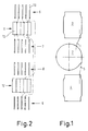
- FIG. 1 2 of the receptacle for a patch cord with the ends 1 and 5 is designated.
- Fibers with a fixed secondary coating that have an outside diameter of about 0.9 mm are particularly suitable as patch cords that contain only one optical fiber.
- the housings 3 and 4 serve to accommodate splice connections, each with an optical waveguide of a first cable or a second cable.
- the length of the patch cords should be selected according to the distances between the housings 3 and 4. For the majority of cases occurring in practice, it is sufficient if two lengths 1 and 5 of 0.5 m each can be extended on both sides of the receptacle, in which case the total length of the marshalling line, including the turns remaining inside is about 2 m.
- ends 1 and 5 are pulled out and pushed back into housings 3 and 4 after the splice connections have been put down.
- plug connections could also be selected instead of splice connections. Then the ends 1 and 5 would have to be provided with plug elements.
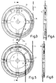
- FIGS. 3 and 4 and 5 and 6 show receptacles which are specially adapted for the method according to the invention. It is important, on the one hand, that large lengths of shunting lines can be accommodated in containers that take up as little space as possible, and that, on the other hand, the end sections can be retracted and removed easily and smoothly. Furthermore, a minimum bending radius permissible for fiber optic cables must also not be undercut for the turns of the marshalling cables within the receptacles.
- the shunting lines 14 and 15 are spirally wound in one plane in several turns, of which only three are shown for better visibility, around a core 16 and 17, respectively, the diameter of which is about 60 mm, so that even when the innermost ones are in close contact Winding at the core the minimum permissible bending radius is not exceeded.
- the cores 16 and 17 connect in the middle each a rear guide wall 18 or 19 and front guide walls, which are designed as narrow radial spokes 20 and 21 and are each interrupted by oblique to the tangent of the turns insertion slots 22 and 23 through which the Windings of the jumper cables 20 and 21 can be inserted.
- the oblique course of the slots 22 and 23 prevents the turns from accidentally sliding out again.
- the guide walls on both sides enclose a guide space with a small height h between them, which is slightly larger than the diameter of the shunting line and should not exceed about 1.3 times its diameter. Then a smooth, orderly and intersection-free guidance of the turns is guaranteed.
- peripheral walls 28 and 29 The ends 24 and 25 emanating from the radially outermost turn expediently emerge through gaps 26 and 27 of the preferably cylindrical peripheral walls 28 and 29.
- the peripheral walls can, for example, also be square, in which case the outermost windings rest at four points.
- FIGS. 5 and 6 An embodiment according to FIGS. 5 and 6 is recommended.
- the end 31 of the marshalling line 15 starting from the inner turn is guided up to point 32 into a guide channel which extends from the peripheral wall 29 to Circumferential surface of the core 17 extends in the guide wall 19, then is deflected in an adapted groove 33 in the core 17 obliquely or slightly curved S-shaped into the winding plane. This prevents any friction between the end 31 and the turns of the switching line 25 in the turn space.
- the jumper cables 24 and 25 are normally inserted in such a way that approximately the same lengths can be pulled out on both sides.
- the ends can be pulled out or pushed in particularly easily if both are moved simultaneously. If different lengths of the two ends are required, in particular if only one end is too short for a distant connection point, this can be pulled out further if the other end is pushed in at the same time or alternately piece by piece.
- d is the diameter of the core and D is the diameter of the peripheral walls 28 or 29 or the maximum possible diameter of the outermost turn.
- d o is the diameter of the patch cord.
- the value D should be selected as follows: This dimensioning results in the smallest possible dimensions.
Landscapes
- Physics & Mathematics (AREA)
- General Physics & Mathematics (AREA)
- Optics & Photonics (AREA)
- Mechanical Coupling Of Light Guides (AREA)
- Light Guides In General And Applications Therefor (AREA)
Claims (9)
- Procédé pour établir une connexion entre deux lignes optiques (6,7, 8, 9) au moyen d'une ligne d'aiguillage individuelle dont les extrémités (1, 5) sont reliées chacune à l'une des extrémités des deux lignes optiques (6, 7, 8, 9), la ligne d'aiguillage optique (14, 15) qui comporte un guide de lumière étant disposé dans un dispositif de stockage (2) en forme de cassette, qui présente des parois latérales (18 à 21, 28, 29) entre lesquelles est formé de l'espace de stockage, un noyau et des ouvertures (26, 27, 29a) par lesquelles est sortie souplement chaque fois une extrémité de la ligne d'aiguillage optique (14, 15), des parties des deux extrémités de la ligne d'aiguillage (14, 15) étant réintroduites de façon peu serrée et étant guidés par les parois latérales (18 à 21, 28, 29), des moyens de guidage étant disponibles pour un guidage peu serré de l'une des extrémités pouvant être sortie lorsque ladite extrémité est réintroduite au-dessus des spires enroulées, de sorte que peur l'établissement d'une connexion avec les extrémités des deux lignes optiques (6, 7, 8, 9) des longueurs nécessaires de la ligne d'aiguillage stockée peuvent être sorties les unes indépendamment des autres du dispositif de stockage (2) et qu'elles en sont sorties avant l'établissement de la connexion, après l'établissement de la connexion des longueurs excessives étant à nouveau réintroduites dans ledit dispositif.
- Dispositif de stockage conçu pour la mise en oeuvre du procédé selon la revendication 1, caractérisé en ce qu'il présente disposé centralement entre deux parois de guidage latérales (18, 20 respectivement 19, 21) un noyau essentiellement cylindrique dont le diamètre est au moins égal à 40 mm, en ce que l'écartement h séparant les parois de guidage se situe dans la gamme do < h < 1,3 do, lorsque do est le diamètre de la ligne d'aiguillage, en ce que la ligne d'aiguillage (14, 15) est enroulée en spirale autour le noyau dans un seul plan de manière à constituer au moins deux spires, en ce que l'extrémité (24, 25) de la spire extérieure est guidée à travers une ouverture pratiquée dans la paroi latérale (28, 29) espacée du noyau et en ce que l'extrémité (30, 31) de la spire intérieure est sortie obliquement de l'espace d'enroulement en passant entre les parois de guidage latérales (18, 20 respectivement 19, 21) et au-dessus des spires pour s'étendre vers un oeillet de guidage (29) disposé radialement à l'extérieur de l'espace d'enroulement.
- Dispositif de stockage selon la revendication 2, caractérisé en ce que l'extrémité (31) de la spire intérieure est guidée dans un canal de guidage lorsqu'elle s'étend vers un point qui touche au moins à peu près à la surface extérieure du noyau (17) dans une zone située à l'extérieur de l'espace d'enroulement.
- Dispositif de stockage selon la revendication 3, caractérisé en ce que dans une zone angulaire prédéterminée le canal de guidage s'étend de façon essentiellement concentrique par rapport au noyau (17) et le cas échéant obliquement dans sa zone extérieure, alors que le canal de guidage s'étendant au-dessus des spires à l'extérieur de l'espace occupé par les spires est guidé dans un plan parallèle avantageusement à l'intérieur d'une paroi de guidage.
- Procédé selon la revendication 1 utilisant un dispositif de stockage conçu selon l'une des revendications 2 à 4, caractérisé en ce que les deux extrémités (24, 30 respectivement 25, 31) de la ligne d'aiguillage peuvent être sorties respectivement réintroduites simultanément et uniformément.
- Procédé selon la revendication 1 utilisant un dispositif de stockage conçu selon l'une des revendications 2 à 4, caractérisé en ce que l'une des deux extrémités (24 respectivement 25, ou 30 respectivement 31) de la ligne d'aiguillage est sortie du dispositif de stockage et que l'autre extrémité (30 respectivement 31, ou 24 respectivement 25) y est réintroduite simultanément ou alternativement en petites étapes.
- Dispositif de stockage selon l'une des revendications 2 à 4, caractérisé en ce qu'au moins l'une des parois de guidage est constituée au moins de trois parties radiales (20, 21) a forme de rayon espacées tangentiellement.
- Dispositif de stockage selon la revendication 7, caractérisé en ce que dans la zone centrale les parties (20, 21) sont séparées par des fentes d'introduction (22, 23) s'étendant obliquement à la tangente des spires.
- Dispositif de stockage selon l'une des revendications 2 à 4 ou 7 et 8, caractérisé en ce que le nombre de spires n est égal à
 D est le diamètre maximal de la spire extérieure,d est le diamètre du noyau etdo est le diamètre de la ligne d'aiguillage.
Applications Claiming Priority (2)
| Application Number | Priority Date | Filing Date | Title |
|---|---|---|---|
| DE3532312 | 1985-09-11 | ||
| DE19853532312 DE3532312A1 (de) | 1985-09-11 | 1985-09-11 | Verfahren zur herstellung einer verbindung zwischen zwei optischen leitungen und anordnung zur ausuebung des verfahrens |
Publications (3)
| Publication Number | Publication Date |
|---|---|
| EP0215520A2 EP0215520A2 (fr) | 1987-03-25 |
| EP0215520A3 EP0215520A3 (en) | 1988-11-30 |
| EP0215520B1 true EP0215520B1 (fr) | 1994-05-04 |
Family
ID=6280598
Family Applications (1)
| Application Number | Title | Priority Date | Filing Date |
|---|---|---|---|
| EP86201541A Expired - Lifetime EP0215520B1 (fr) | 1985-09-11 | 1986-09-09 | Procédé de fabrication d'une connexion entre deux fibres optiques et dispositif pour la réalisation de ce procédé |
Country Status (4)
| Country | Link |
|---|---|
| US (1) | US4900121A (fr) |
| EP (1) | EP0215520B1 (fr) |
| JP (1) | JPH083566B2 (fr) |
| DE (2) | DE3532312A1 (fr) |
Families Citing this family (27)
| Publication number | Priority date | Publication date | Assignee | Title |
|---|---|---|---|---|
| US4793682A (en) * | 1988-01-11 | 1988-12-27 | Gte Products Corporation | Fiber optic splice and fiber holder and housing therefor |
| US4846565A (en) * | 1988-06-10 | 1989-07-11 | Gte Products Corporation | Emergency preterminated cable apparatus |
| DE3838428A1 (de) * | 1988-11-12 | 1990-05-31 | Philips Patentverwaltung | Schaltverteiler zur herstellung von frei waehlbaren optischen steckverbindungen |
| US5163988A (en) * | 1990-04-03 | 1992-11-17 | Fujikura Ltd. | Method of preventing twisting of a fushion-spliced, tube-removed fiber portion in the process of encasing the fiber portion in a casing |
| US5109983A (en) * | 1991-01-28 | 1992-05-05 | Minnesota Mining And Manufacturing Company | Package for an optical fiber jumper |
| IT1248299B (it) * | 1991-05-07 | 1995-01-05 | Specimas S P A | Dispositivo per mantenere fissa, relativamente ad un lettore ottico, l'estremita' di un cavo ottico incorporato in un cavo di potenza svolgibile da un tamburo |
| EP0519210B1 (fr) * | 1991-06-10 | 1996-02-28 | International Business Machines Corporation | Connecteur optique rétractable pour des ordinateurs |
| US5247603A (en) * | 1992-01-24 | 1993-09-21 | Minnesota Mining And Manufacturing Company | Fiber optic connection system with exchangeable cross-connect and interconnect cards |
| US5189724A (en) * | 1992-02-24 | 1993-02-23 | Hughes Aircraft Company | Arrangement for accommodating excess length of optical fibers |
| US5841608A (en) * | 1994-08-30 | 1998-11-24 | Fujitsu Limited | Head slider with projections arranged on rails thereof |
| US5935292A (en) * | 1997-01-08 | 1999-08-10 | 3M Innovative Properties Company | Annealing mold and retainer for making a fiber optic current sensor |
| US5802237A (en) * | 1997-04-18 | 1998-09-01 | Minnesota Mining And Manufacturing Company | Optical fiber organizer |
| FR2769377B1 (fr) * | 1997-10-07 | 2000-11-24 | France Telecom | Boitier de piquage de fibres optiques dans un cable de fibres optiques |
| US6215937B1 (en) | 1998-09-24 | 2001-04-10 | Thomas & Betts International, Inc. | Adjustable fiber optic strand storage unit |
| US6507691B1 (en) | 1999-03-22 | 2003-01-14 | Tyco Electronics Corporation | Fiber optic splice organizer with splicing tray and associated method |
| DE60017284T2 (de) * | 1999-11-30 | 2005-12-08 | Corning O.T.I. S.R.L. | Optische vorrichtung mit einer faseroptischen komponente |
| US6278830B1 (en) | 2000-01-12 | 2001-08-21 | Ortronics, Inc. | Bend limiting fiber management clip |
| NO317652B1 (no) * | 2002-05-03 | 2004-11-29 | Nexans | Oppkveilingsramme for kabel med optiske fibre |
| US7027695B2 (en) * | 2003-06-28 | 2006-04-11 | General Dynamics Advanced Information Systems, Inc. | Fiber transition segment for use in optical fiber hydrophone array |
| US6870997B2 (en) * | 2003-06-28 | 2005-03-22 | General Dynamics Advanced Information Systems, Inc. | Fiber splice tray for use in optical fiber hydrophone array |
| US6934451B2 (en) * | 2003-06-28 | 2005-08-23 | General Dynamics Advanced Information Systems, Inc. | Mount for use in optical fiber hydrophone array |
| US6865334B2 (en) * | 2003-06-28 | 2005-03-08 | General Dynamics Advanced Information Systems, Inc. | Termination assembly for use in optical fiber hydrophone array |
| US6879545B2 (en) * | 2003-06-28 | 2005-04-12 | General Dynamics Advanced Information Systems, Inc. | Woven fiber protection cable assembly for use in optical fiber hydrophone array |
| US6904222B2 (en) * | 2003-06-28 | 2005-06-07 | General Dynamics Advanced Information Systems, Inc. | Optical fiber splice protection apparatus for use in optical fiber hydrophone array |
| JP5245240B2 (ja) * | 2006-10-26 | 2013-07-24 | 住友電気工業株式会社 | 光ファイバコイル収納容器及び光ファイバモジュール |
| US7428350B1 (en) * | 2007-07-18 | 2008-09-23 | Schlumberger Technology Corporation | Optical turnaround system |
| GB2507741A (en) * | 2012-11-07 | 2014-05-14 | Bombardier Transp Gmbh | Cable bearing element for inductive power coupling |
Citations (3)
| Publication number | Priority date | Publication date | Assignee | Title |
|---|---|---|---|---|
| DE2544828A1 (de) * | 1975-10-04 | 1977-04-14 | Heinz Koenig | Kabeltrommel zum automatischen wiederaufwickeln eines kabels |
| DE2607950A1 (de) * | 1976-02-27 | 1977-09-01 | Kabel Metallwerke Ghh | Vorrichtung zum selbsttaetigen aufwickeln einer elektrischen leitung auf eine trommel |
| EP0116480A1 (fr) * | 1983-01-05 | 1984-08-22 | SAT (Société Anonyme de Télécommunications),Société Anonyme | Boîte de raccordement et de brassage pour fibres optiques |
Family Cites Families (14)
| Publication number | Priority date | Publication date | Assignee | Title |
|---|---|---|---|---|
| DE2721300C2 (de) * | 1977-05-12 | 1982-10-07 | Licentia Patent-Verwaltungs-Gmbh, 6000 Frankfurt | Ringelement einer Kassette für Lichtleitfasern |
| NL7900432A (nl) * | 1979-01-19 | 1980-07-22 | Nkf Groep Bv | Glasvezel verbindingsmof. |
| US4359262A (en) * | 1980-06-30 | 1982-11-16 | Northern Telecom Limited | Tray for organizing optical fiber splices and enclosures embodying such trays |
| DE3025700C2 (de) * | 1980-07-07 | 1983-11-17 | Siemens AG, 1000 Berlin und 8000 München | Muffe für hochpaarige Lichtwellenleiter-Kabel |
| JPS57144511A (en) * | 1981-03-03 | 1982-09-07 | Nippon Telegr & Teleph Corp <Ntt> | Processing part for extra length of core wire of optical fiber |
| DE3118173A1 (de) * | 1981-05-08 | 1982-11-25 | Philips Kommunikations Industrie AG, 8500 Nürnberg | Lichtwellenleiter enthaltende, druckgasueberwachte kabelanordnung mit verbindungsmuffe |
| JPS599311U (ja) * | 1982-07-12 | 1984-01-21 | 古河電気工業株式会社 | 光ケ−ブル接続箱 |
| DE3248003A1 (de) * | 1982-12-24 | 1984-06-28 | Philips Kommunikations Industrie AG, 8500 Nürnberg | Kabelmuffe fuer lichtwellenleiter-verbindungen |
| JPS60149010A (ja) * | 1984-01-17 | 1985-08-06 | Fujitsu Ltd | 光フアイバ接続余長部の収容装置 |
| FR2559916B1 (fr) * | 1984-02-21 | 1989-02-24 | Constr Telephoniques | Methode utilisee dans le raccordement de fibres optiques pour constituer et stocker un troncon de fibre en reserve et dispositif s'y rapportant |
| FR2561002B1 (fr) * | 1984-03-07 | 1989-02-24 | Constr Telephoniques | Dispositif pour le stockage d'un troncon de fibre optique de longueur variable |
| FR2566756B1 (fr) * | 1984-06-27 | 1987-05-07 | Cit Alcatel | Boite de lovage pour cable |
| FR2573877B1 (fr) * | 1984-11-26 | 1988-02-05 | Telecommunications Sa | Boitier pour cables a fibres optiques et son application aux raccordements entre fibres |
| DE3532314A1 (de) * | 1985-09-11 | 1987-03-12 | Philips Patentverwaltung | Aufnahmeeinrichtung fuer eine vorratslaenge einer optischen leitung |
-
1985
- 1985-09-11 DE DE19853532312 patent/DE3532312A1/de not_active Withdrawn
-
1986
- 1986-09-09 DE DE3689827T patent/DE3689827D1/de not_active Expired - Fee Related
- 1986-09-09 EP EP86201541A patent/EP0215520B1/fr not_active Expired - Lifetime
- 1986-09-11 JP JP61212846A patent/JPH083566B2/ja not_active Expired - Lifetime
-
1989
- 1989-02-13 US US07/311,365 patent/US4900121A/en not_active Expired - Fee Related
Patent Citations (3)
| Publication number | Priority date | Publication date | Assignee | Title |
|---|---|---|---|---|
| DE2544828A1 (de) * | 1975-10-04 | 1977-04-14 | Heinz Koenig | Kabeltrommel zum automatischen wiederaufwickeln eines kabels |
| DE2607950A1 (de) * | 1976-02-27 | 1977-09-01 | Kabel Metallwerke Ghh | Vorrichtung zum selbsttaetigen aufwickeln einer elektrischen leitung auf eine trommel |
| EP0116480A1 (fr) * | 1983-01-05 | 1984-08-22 | SAT (Société Anonyme de Télécommunications),Société Anonyme | Boîte de raccordement et de brassage pour fibres optiques |
Also Published As
| Publication number | Publication date |
|---|---|
| EP0215520A2 (fr) | 1987-03-25 |
| DE3689827D1 (de) | 1994-06-09 |
| EP0215520A3 (en) | 1988-11-30 |
| US4900121A (en) | 1990-02-13 |
| DE3532312A1 (de) | 1987-03-12 |
| JPS6261011A (ja) | 1987-03-17 |
| JPH083566B2 (ja) | 1996-01-17 |
Similar Documents
| Publication | Publication Date | Title |
|---|---|---|
| EP0215520B1 (fr) | Procédé de fabrication d'une connexion entre deux fibres optiques et dispositif pour la réalisation de ce procédé | |
| EP0214701B1 (fr) | Boucle de surlongueur pour une fibre optique | |
| DE3133586C2 (de) | Spleißträger für Lichtwellenleiter-Kabel | |
| DE3025700C2 (de) | Muffe für hochpaarige Lichtwellenleiter-Kabel | |
| EP0492206B1 (fr) | Câble optique ayant guides d'onde lumineuses multiples | |
| EP0281196B1 (fr) | Dispositif de raccordement pour la longueur de réserve d'au moins un guide d'ondes lumineuses | |
| DE69227810T2 (de) | Vorrichtung zum Unterbringen der Reservelänge einer Ader am Ende eines optischen Kabels | |
| EP1567902B1 (fr) | Dispositif permettant de manipuler ou de stocker de maniere structuree des guides d'ondes optiques | |
| EP0872750B1 (fr) | Boite de jonction avec un dispositif de retenue de cassettes pour le stockage de fibres optiques ainsi que leurs épissures | |
| EP0258520A2 (fr) | Câble de communication avec guides d'ondes lumineuses | |
| DE60003069T2 (de) | Führung von glasfasern | |
| EP0579019A1 (fr) | Dispositif pour deposer cassettes d'épissure pour guides d'ondes optiques dans un manchon à câble | |
| DE2914217A1 (de) | Kassette zur aufnahme der vorratslaengen von lichtleitfasern | |
| DE4438668A1 (de) | Kassette zum Ablegen von Lichtwellenleiterüberlängen und Lichtwellenleiterspleißverbindungen | |
| DE2734796C3 (de) | Verbinder für Kabel, die Lichtleitfasern enthalten | |
| DE2651080C2 (de) | Verbindungs- oder Aufteilungsmuffe für Lichtleitfasern und -kabel | |
| DE60000727T2 (de) | Management für optische fasern | |
| DE3812143A1 (de) | Verfahren zur identifizierung einzelner lichtwellenleiter innerhalb eines vieladrigen optischen kabels | |
| DE4417767C2 (de) | Anordnung zum Spleißen und Bevorraten von Lichtwellenleitern | |
| DE69206089T2 (de) | Vorrichtung zur Einbringung von optischen Faserbändern in die schraubenlinienförmigen Nuten eines Trogelements. | |
| EP0412603B1 (fr) | Dispositif de stockage pour la surlongueur d'un conducteur optique | |
| DE9115060U1 (de) | Spleißkassette für Lichtwellenleiter | |
| DE102021113534B3 (de) | Werkstückträger für die Aufnahme eines zwei Strangenden aufweisenden Leitungsstranges zur automatisierten Verarbeitung | |
| EP0498308A1 (fr) | Câble optique et procédé de sa fabrication | |
| DE4320941C2 (de) | Aufwickelvorrichtung für Lichtwellenleiter |
Legal Events
| Date | Code | Title | Description |
|---|---|---|---|
| PUAI | Public reference made under article 153(3) epc to a published international application that has entered the european phase |
Free format text: ORIGINAL CODE: 0009012 |
|
| AK | Designated contracting states |
Kind code of ref document: A2 Designated state(s): DE FR GB |
|
| RAP1 | Party data changed (applicant data changed or rights of an application transferred) |
Owner name: N.V. PHILIPS' GLOEILAMPENFABRIEKEN Owner name: PHILIPS PATENTVERWALTUNG GMBH |
|
| PUAL | Search report despatched |
Free format text: ORIGINAL CODE: 0009013 |
|
| AK | Designated contracting states |
Kind code of ref document: A3 Designated state(s): DE FR GB |
|
| 17P | Request for examination filed |
Effective date: 19890517 |
|
| 17Q | First examination report despatched |
Effective date: 19910715 |
|
| GRAA | (expected) grant |
Free format text: ORIGINAL CODE: 0009210 |
|
| AK | Designated contracting states |
Kind code of ref document: B1 Designated state(s): DE FR GB |
|
| REF | Corresponds to: |
Ref document number: 3689827 Country of ref document: DE Date of ref document: 19940609 |
|
| GBT | Gb: translation of ep patent filed (gb section 77(6)(a)/1977) |
Effective date: 19940720 |
|
| ET | Fr: translation filed | ||
| PLBE | No opposition filed within time limit |
Free format text: ORIGINAL CODE: 0009261 |
|
| STAA | Information on the status of an ep patent application or granted ep patent |
Free format text: STATUS: NO OPPOSITION FILED WITHIN TIME LIMIT |
|
| 26N | No opposition filed | ||
| REG | Reference to a national code |
Ref country code: FR Ref legal event code: CD |
|
| REG | Reference to a national code |
Ref country code: FR Ref legal event code: TP |
|
| REG | Reference to a national code |
Ref country code: GB Ref legal event code: 732E |
|
| PGFP | Annual fee paid to national office [announced via postgrant information from national office to epo] |
Ref country code: GB Payment date: 19990813 Year of fee payment: 14 |
|
| PGFP | Annual fee paid to national office [announced via postgrant information from national office to epo] |
Ref country code: FR Payment date: 19990817 Year of fee payment: 14 |
|
| PGFP | Annual fee paid to national office [announced via postgrant information from national office to epo] |
Ref country code: DE Payment date: 19990820 Year of fee payment: 14 |
|
| PG25 | Lapsed in a contracting state [announced via postgrant information from national office to epo] |
Ref country code: GB Free format text: LAPSE BECAUSE OF NON-PAYMENT OF DUE FEES Effective date: 20000909 |
|
| GBPC | Gb: european patent ceased through non-payment of renewal fee |
Effective date: 20000909 |
|
| PG25 | Lapsed in a contracting state [announced via postgrant information from national office to epo] |
Ref country code: FR Free format text: LAPSE BECAUSE OF NON-PAYMENT OF DUE FEES Effective date: 20010531 |
|
| PG25 | Lapsed in a contracting state [announced via postgrant information from national office to epo] |
Ref country code: DE Free format text: LAPSE BECAUSE OF NON-PAYMENT OF DUE FEES Effective date: 20010601 |
|
| REG | Reference to a national code |
Ref country code: FR Ref legal event code: ST |