EP0215616A2 - Procédé pour assembler des modèles perdus en mousse utilisés dans le procédé de coulée avec modèle vaporisable - Google Patents
Procédé pour assembler des modèles perdus en mousse utilisés dans le procédé de coulée avec modèle vaporisable Download PDFInfo
- Publication number
- EP0215616A2 EP0215616A2 EP86306863A EP86306863A EP0215616A2 EP 0215616 A2 EP0215616 A2 EP 0215616A2 EP 86306863 A EP86306863 A EP 86306863A EP 86306863 A EP86306863 A EP 86306863A EP 0215616 A2 EP0215616 A2 EP 0215616A2
- Authority
- EP
- European Patent Office
- Prior art keywords
- assembly
- pattern
- foam
- pilot
- segments
- Prior art date
- Legal status (The legal status is an assumption and is not a legal conclusion. Google has not performed a legal analysis and makes no representation as to the accuracy of the status listed.)
- Granted
Links
Images


Classifications
-
- B—PERFORMING OPERATIONS; TRANSPORTING
- B22—CASTING; POWDER METALLURGY
- B22C—FOUNDRY MOULDING
- B22C7/00—Patterns; Manufacture thereof so far as not provided for in other classes
- B22C7/02—Lost patterns
- B22C7/023—Patterns made from expanded plastic materials
- B22C7/026—Patterns made from expanded plastic materials by assembling preformed parts
-
- B—PERFORMING OPERATIONS; TRANSPORTING
- B29—WORKING OF PLASTICS; WORKING OF SUBSTANCES IN A PLASTIC STATE IN GENERAL
- B29C—SHAPING OR JOINING OF PLASTICS; SHAPING OF MATERIAL IN A PLASTIC STATE, NOT OTHERWISE PROVIDED FOR; AFTER-TREATMENT OF THE SHAPED PRODUCTS, e.g. REPAIRING
- B29C65/00—Joining or sealing of preformed parts, e.g. welding of plastics materials; Apparatus therefor
- B29C65/02—Joining or sealing of preformed parts, e.g. welding of plastics materials; Apparatus therefor by heating, with or without pressure
- B29C65/40—Applying molten plastics, e.g. hot melt
-
- B—PERFORMING OPERATIONS; TRANSPORTING
- B29—WORKING OF PLASTICS; WORKING OF SUBSTANCES IN A PLASTIC STATE IN GENERAL
- B29C—SHAPING OR JOINING OF PLASTICS; SHAPING OF MATERIAL IN A PLASTIC STATE, NOT OTHERWISE PROVIDED FOR; AFTER-TREATMENT OF THE SHAPED PRODUCTS, e.g. REPAIRING
- B29C65/00—Joining or sealing of preformed parts, e.g. welding of plastics materials; Apparatus therefor
- B29C65/48—Joining or sealing of preformed parts, e.g. welding of plastics materials; Apparatus therefor using adhesives, i.e. using supplementary joining material; solvent bonding
- B29C65/4805—Joining or sealing of preformed parts, e.g. welding of plastics materials; Apparatus therefor using adhesives, i.e. using supplementary joining material; solvent bonding characterised by the type of adhesives
- B29C65/481—Non-reactive adhesives, e.g. physically hardening adhesives
- B29C65/4815—Hot melt adhesives, e.g. thermoplastic adhesives
-
- B—PERFORMING OPERATIONS; TRANSPORTING
- B29—WORKING OF PLASTICS; WORKING OF SUBSTANCES IN A PLASTIC STATE IN GENERAL
- B29C—SHAPING OR JOINING OF PLASTICS; SHAPING OF MATERIAL IN A PLASTIC STATE, NOT OTHERWISE PROVIDED FOR; AFTER-TREATMENT OF THE SHAPED PRODUCTS, e.g. REPAIRING
- B29C66/00—General aspects of processes or apparatus for joining preformed parts
- B29C66/01—General aspects dealing with the joint area or with the area to be joined
- B29C66/05—Particular design of joint configurations
- B29C66/301—Three-dimensional joints, i.e. the joined area being substantially non-flat
-
- B—PERFORMING OPERATIONS; TRANSPORTING
- B29—WORKING OF PLASTICS; WORKING OF SUBSTANCES IN A PLASTIC STATE IN GENERAL
- B29C—SHAPING OR JOINING OF PLASTICS; SHAPING OF MATERIAL IN A PLASTIC STATE, NOT OTHERWISE PROVIDED FOR; AFTER-TREATMENT OF THE SHAPED PRODUCTS, e.g. REPAIRING
- B29C66/00—General aspects of processes or apparatus for joining preformed parts
- B29C66/50—General aspects of joining tubular articles; General aspects of joining long products, i.e. bars or profiled elements; General aspects of joining single elements to tubular articles, hollow articles or bars; General aspects of joining several hollow-preforms to form hollow or tubular articles
- B29C66/51—Joining tubular articles, profiled elements or bars; Joining single elements to tubular articles, hollow articles or bars; Joining several hollow-preforms to form hollow or tubular articles
- B29C66/54—Joining several hollow-preforms, e.g. half-shells, to form hollow articles, e.g. for making balls, containers; Joining several hollow-preforms, e.g. half-cylinders, to form tubular articles
- B29C66/547—Joining several hollow-preforms, e.g. half-cylinders, to form tubular articles, e.g. endless tubes
- B29C66/5472—Joining several hollow-preforms, e.g. half-cylinders, to form tubular articles, e.g. endless tubes for making elbows or V-shaped pieces
- B29C66/54721—Joining several hollow-preforms, e.g. half-cylinders, to form tubular articles, e.g. endless tubes for making elbows or V-shaped pieces for making L-shaped pieces
-
- B—PERFORMING OPERATIONS; TRANSPORTING
- B29—WORKING OF PLASTICS; WORKING OF SUBSTANCES IN A PLASTIC STATE IN GENERAL
- B29C—SHAPING OR JOINING OF PLASTICS; SHAPING OF MATERIAL IN A PLASTIC STATE, NOT OTHERWISE PROVIDED FOR; AFTER-TREATMENT OF THE SHAPED PRODUCTS, e.g. REPAIRING
- B29C66/00—General aspects of processes or apparatus for joining preformed parts
- B29C66/70—General aspects of processes or apparatus for joining preformed parts characterised by the composition, physical properties or the structure of the material of the parts to be joined; Joining with non-plastics material
- B29C66/72—General aspects of processes or apparatus for joining preformed parts characterised by the composition, physical properties or the structure of the material of the parts to be joined; Joining with non-plastics material characterised by the structure of the material of the parts to be joined
- B29C66/727—General aspects of processes or apparatus for joining preformed parts characterised by the composition, physical properties or the structure of the material of the parts to be joined; Joining with non-plastics material characterised by the structure of the material of the parts to be joined being porous, e.g. foam
-
- B—PERFORMING OPERATIONS; TRANSPORTING
- B29—WORKING OF PLASTICS; WORKING OF SUBSTANCES IN A PLASTIC STATE IN GENERAL
- B29C—SHAPING OR JOINING OF PLASTICS; SHAPING OF MATERIAL IN A PLASTIC STATE, NOT OTHERWISE PROVIDED FOR; AFTER-TREATMENT OF THE SHAPED PRODUCTS, e.g. REPAIRING
- B29C66/00—General aspects of processes or apparatus for joining preformed parts
- B29C66/70—General aspects of processes or apparatus for joining preformed parts characterised by the composition, physical properties or the structure of the material of the parts to be joined; Joining with non-plastics material
- B29C66/71—General aspects of processes or apparatus for joining preformed parts characterised by the composition, physical properties or the structure of the material of the parts to be joined; Joining with non-plastics material characterised by the composition of the plastics material of the parts to be joined
-
- B—PERFORMING OPERATIONS; TRANSPORTING
- B29—WORKING OF PLASTICS; WORKING OF SUBSTANCES IN A PLASTIC STATE IN GENERAL
- B29K—INDEXING SCHEME ASSOCIATED WITH SUBCLASSES B29B, B29C OR B29D, RELATING TO MOULDING MATERIALS OR TO MATERIALS FOR MOULDS, REINFORCEMENTS, FILLERS OR PREFORMED PARTS, e.g. INSERTS
- B29K2105/00—Condition, form or state of moulded material or of the material to be shaped
- B29K2105/04—Condition, form or state of moulded material or of the material to be shaped cellular or porous
-
- B—PERFORMING OPERATIONS; TRANSPORTING
- B29—WORKING OF PLASTICS; WORKING OF SUBSTANCES IN A PLASTIC STATE IN GENERAL
- B29L—INDEXING SCHEME ASSOCIATED WITH SUBCLASS B29C, RELATING TO PARTICULAR ARTICLES
- B29L2031/00—Other particular articles
- B29L2031/757—Moulds, cores, dies
Definitions
- This invention relates to the art of casting metals by use of consumable or evaporative patterns and, more particularly, to the construction of such patterns for making complex castings
- foam patterns (comprised of polystyrene or polyurethane or polyethylene) in the casting of metals has been known for at least the past 20 years. During this period substantially all of such foam patterns have been of simple, unitary shapes. In a few instances, where a complex pattern was necessarily divided into parts to allow the foam parts to be die cast, such parts had to be joined together to complete the pattern.
- the splitting of the entire pattern into parts is necessitated by the ability to define, by dies, all the surfaces of the pattern; die molding must allow the dies to be removed along a straight line direction and thus will not allow for undercut or return surfaces.
- die molding must allow the dies to be removed along a straight line direction and thus will not allow for undercut or return surfaces.
- the pattern itself is split into at least three pattern parts to obtain the definition of such internally complex surfaces.
- Foam pattern parts have been joined together prior to insertion in the mold, either by solvent welding, such as illustrated in U . S . patent 3,675,708 (which unfortunately results in distortion of the welded surfaces), or hot melt adhesive bonding, such as shown in U.S. patent 4,243,093, which inherently requires the application of hot melt glue along straight, geometrically level lines or surfaces.
- Commercially available hot melt adhesive bonding equipment (which may be used for mass production joining of such foam pattern parts) is preferably limited to (a) dispensing an extruded liquid bead, or (b) printing the hot melt glue onto flat surfaces or straight margins by kissing a hot melt glue-holding platen against the margins which must receive glue.
- a complex consumable foam pattern assembly for use in the evaporative pattern metal casting process, comprising mating first and second clamshell-shaped foam members said first and second foam members meeting along exteriorly exposed joint margins defined by mateable surfaces extending along opposite sides of each of said members, at least one other foam member nestable totally within the mated assembly of said first and second members and nestable without joint margins exposed to the exterior of said assembly, surface means enclosed within said mater assembly for piloting said first, second and other members into mating relationship and adhesive means bonding said first and other members together and said second member to the assembly of said first and other member.
- a method of assembling foam pattern segments into a unitary assembly comprising; (a) molding first, second and third consumable foam pattern segments, said first and second pattern segments being mateable and effective to meet along exteriorly disposed joint margins defined by mateable surfaces extending along opposite sides of each of said first and second segments, and a third pattern segment nestable totally within the assembly of said first and second segments and nestable without joint margins exposed to the exterior of the mated assembly, said first and third segments being molded with interiorly disposed pilot surfaces effective to constitute a double-ply foam wall when mated, said first and third segments being molded with interiorly disposed second pilot surfaces effective to constitute a double-ply foam wall when mated, said pilot surfaces also having stop means to limit movement of the pilot surfaces; (b) mating said first segment with said third segment by moving said first pilot surfaces together along the plane of said surfaces until said stop means is bottomed out; and (c) mating said second segment with the assembly of said third and first segments by moving said second
- the exterior joint of the assembly is reduced linearly by about at least 20% compared to an assembly where all the pattern parts have most surfaces exposed to the exterior of said assembly.
- the use of stepped pattern part joints is eliminated, obviating the difficulty in applying glue uniformly to such serrations, and also because stepped joints greatly increase the difficulty in obtaining accurate match-up of mating margins to be bonded due to tooling variations and glue or foam part density variability.
- the surface means for piloting the first, second and other member comprises: (a) interiorly disposed mating planar surfaces on the first and other member effective to constitute a double-ply foam wall when mated, and (b) interiorly disposed second pilot surfaces on the second and other member effective, when mated, to constitute a double-ply foam wall.
- the assembly may additionally comprise stop means to limit movement of the first pilot surfaces in a first direction along the pilot surfaces and transverse to the first direction, and stop means to limit movement of the second pilot surfaces in a similar manner.
- first and second pilot surfaces additionally comprise, respectively, first and second mating wedging surfaces to accurately align the pilot surfaces.
- the evaporative casting process employs an expendable or consumable foam replica of the part to be cast.
- Many complex castings such as an intake manifold for an engine, requires three or more foam members which are segments of the overall pattern to produce the product shape.
- the individual foam segments are glued together to make up the complete foam replica, which is then coated with a refractory wash coating prior to pouring of the metal into the metal casting mold using such pattern.
- the integrity of the glue joints between these foam segments and exposed to the exterior of the pattern affects the quality of the casting.
- An absence of glue, or glue which is improperly applied or misplaced enables the refractory wash to seep into the glue joint.
- the presence of this refractory wash in the foam to foam margin interface results in an absence of metal, creating a defect that must be repaired in the final metal casting. Such repair is usually carried out by impregnation, welding, or eventually scrapping the entire metal casting.
- This invention discloses a foam pattern construction or assembly, and discloses a method for making metal casting utilizing such pattern assembly, which greatly reduces the length of the exterior located glue joint, thereby directly reducing the potential for glue line defects.
- a foam pattern 10 was developed for casting an intake manifold of aluminum metal, the intake manifold being designed for a four-cylinder engine requiring four conduits to conduct the intake air/fuel mixture to the cylinders from a common air supply.
- This particular intake manifold utilized an entrance or mouth 11 from which four air channels 12-13-14-15 extended therefrom and terminated in four aligned exit openings 16-17-18-19 having their axes aligned along a straight line 20.
- This particular pattern design had a total length of joint margins for gluing of 71 inches, of which 57 inches were externally exposed glue margins which can result in external defects; that is, leaks to the outside of the manifold.
- Internal joint margins are not particularly critical since any slight absence of metal does not result in an external leak and therefore can be tolerated without repairs. It is the externally exposed joint margins that create a problem resulting in casting defects. Thus, if the externally exposed joint margins can be reduced or substantially eliminated, the defects are proportionately reduced.
- the externally exposed joint margins are a series of zig-zag or stepped margins and are not along a continuous geometrical curve; this complicates the problem of applying a uniform deposition of an extruded liquid or foamed glue bead in mass production apparatus techniques.
- the chance for lateral mismatch is significant because there are no surfaces that guide or pilot the particular segmental members together.
- the joint margins for gluing must be simple, smooth, and not complex
- the molding process for defining the foam pattern segments is an inherent limitation on the shape of the segments. Internal passages and undercut surfaces must be defined by dies which must be withdrawn in one linear direction determined by the die molding equipment assembly.
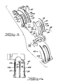
- the assembly 40 is comprised of clamshell-shaped mating foam segments (or members) 41-42 which meet along exteriorly exposed joint margins 44(a-b) and 45(a-b) defined by mateable narrow surfaces extending along opposite sides of each of the segments.
- a third foam segment 43 is nestable totally within the mated assembly of segments 41 and 42; the third segment is joined at mating margins 46-47-48 to segment 41 and at mating margins 49-50-51 to segment 42.
- the segments carry surface means 52, which is enclosed within the assembly, for piloting the segments into accurate mating relationship.
- the surface means 52 comprises interiorly disposed pilot surfaces 53 on segment 41 and surfaces 54 on segment 43 for piloting segments 41-43 together; when segments 41-43 are mated, the surfaces 53 and 54 will constitute a double-ply foam wall; surfaces 53 and 54 mate on both sides of segment 43.
- Surface means 52 also comprises other pilot surfaces 55 on segment 42 and surfaces 56 on segment 43 for piloting segments 42-43 together; again, when segments 42-43 are mated, the surfaces 55-56 will constitute a double-ply foam wall.
- Surfaces 54 and 56 lay on opposite sides of the dotted line shown in Figure 3.
- the surface means 52 additionally comprises stops 46-47-48 (which are mating margins) to limit movement of pilot surfaces 54 relative to surfaces 53 -when the segment 43 is inserted into segment 41 in a first direction 57 along the surfaces. Stops 49-50-51 (which are mating margins) limit movement of pilot surfaces 56 relative to surfaces 55 when segment 42 is inserted onto segment 43 in a direction 58 along the surfaces 56-55.
- The.surface means also has stop shoulders 59a and 59b on segment 41 to limit movement of the surfaces 54-53 in a direction 60 transverse to direction 5.7 and stop shoulders 61a and 61b on segment 42 to limit movement of surfaces 55-56 in a direction transverse to direction 58.
- Liquid adhesive is applied first to margins 59a-59b and to margins 46-47-48; segment 43 is then inserted into segment 41 with surfaces 53-54 piloting the movement and margins 46-47-48 stopping the movement in one direction with stop shoulders 59a-59b stopping the movement in the other direction.
- the open time for liquid adhesives may be relatively short requiring quick, foolproof assembly as made possible by this invention.
- Mating clamshell-shaped foam segments 70-71 are defined and hereafter referred to as first and second members.
- the first and second members 70-71 meet along exteriorly exposed joint margins 73-74, which margins separate the exterior walls of the pattern by way of a surface which curves .along the midsection of the two outer channels.
- the two narrow curved margins 73-74 commensurate in width with the pattern wall through which it is bisected, are spaced at opposite sides of the segments 70-71.
- Margins 73-74 are to mate with margins 103-104 on segment 71.
- the first and second segmental members meet along a curved plane, which plane is defined by a plurality of parallel axes, each being perpendicular or transverse to the axis 75 of the inlet and axis 76 outlet openings of the manifold pattern.
- the meeting plane causes the portions of the segmental members to meet along thin wall margins as severed by such plane.
- the thin wall joint margins exposed to the exterior of the mated assembly (here 73-74) are substantially reduced in length and extend through the midsection of the two side channels of the manifold. The division of the interior channels of the manifold is not exposed to the exterior.
- the width of wall margins 73-74 is approximately .188 of an inch.
- the body of the casting pattern adjacent the inlet opening and the outlet openings is somewhat enlarged to provide for a mass of material for mounting the resultant mating part, and thus permits the foam pattern to have planar surfaces 77-78 adjacent such openings.
- the joining of the pattern segments is principally along the thin wall joint margins 73-74.
- Another foam segment 72 is defined which is nestable totally within the assembly of the first and second clamshell-shaped members.
- the enclosed member 72 is totally enveloped and has no projection to the exterior of the assembly of the first and second members.
- One side 81 of segment 72 is defined by a first curved plane which meets generally with the midsection of the interior channels 78 and 80. Joint margins 83-84-85 lay in the first curved plane.
- the opposite side 82 is defined by a second curved plane which severs the midsection of the exterior (outside) channels 86-87, which second plane aligns with the curved plane defining the first segment 70.
- Segment 72 and segment 70 have mating first pilot surfaces 88-89 in the form of flat side walls, which pilot surfaces 88-89 face each other when mated. Such pilot surfaces are brought into engagement by sliding the segment 72 between the pair of pilot surfaces 88 on the segment 70, such surfaces being spaced apart accurately so that they provide a slight frictional interengagement when so mated.
- First stop means (in the farm of joint margins 83-84-85) meet the inside curved plane 81 of segment 72 to limit the sliding movement of segment 72 in one direction 91. Stop shoulders 90 are provided at the extremities of margins 83-84-85 to limit the sliding motion of the pilot surfaces in a direction transverse to direction 91.
- first mating wedging surfaces 92 are provided on such segments and are adapted to guide the segments together as segment 72 is slightly moved downwardly as it is slid into position toward segment 70.
- second mating pilot surfaces 93-94 are provided which comprise wedging surfaces defined as generally a V configuration on segment 72.
- the surfaces 93 extend along the inside of the pattern wall 95 and define the two outer channels 86-87.
- Complimentary wedging surfaces 94 on segment 71 (forming a V) when mated to the first curved wedging surfaces, define a double-ply foam wall.
- Second wedging surfaces 95 are provided on segment 72, which surfaces 95 form the outer side of the inner channels 79-80 along one portion thereof; complimentary mating wedging surfaces 96 are provided on the segment 7.1 and, when mated, form a double-ply wall.
- the wedging surfaces 95 result in a meeting at the crevice 99 between the two inner channels and the natural curvature of the outer surface of those tubular channels.
- segments 71-72 have second stop means which are the mating joint margins 100-101 resulting from severance of the overall pattern at the curved separation plane 73.
- segment 71 is brought into accurate alignment with the segment 72 by virtue of the wedging surfaces 93-94 and 95-96, said pairs being in opposed orientation to each other; as segment 72 is slid into and slightly down on the segment 72 (as segment 72 sits on the segment 70), the thin joint margins 83-84-85 are accurately placed into abutting relationship.
- liquid glue is deposited as an extruded bead onto the mating joint margins 73-74-83-84-85-101.
- a paraffin based glue which has a melting temperature of about 260°F or greater can be utilized, or a foam hot melting adhesive may be employed which may be made from a polypropylene base and which has a melting temperature of 325° F or greater; however, in the foam condition the glue possesses a surface temperature of less than 160° for an extended period.
- An example of the type of hot melt adhesive that may be employed is E astobond (a trademark of Eastman Kodak Co.) having a model No.
- A-148S such hot melt adhesive is designed for bonding polystyrene with an extremely high bond strength.
- the Eastobond glue is melted in a tank, grid melter, or a bulk melter, and is fed by way of a gear pump or piston pump to a feeding mechanism and applied as an extruded bead through a. nozzle commensurate with the width of the joint margin wall of the foam pattern.
- the application temperature of such Eastobond glue is usually between 350-375°F (177-191°C); the adhesive has a viscosity at 350°F of 42cP, a heat stability (change in viscosity after 100 hours at 350° F ) of about 15%, a density at 73° F of about .89 gm/cm 3 , and a flash point of about 550°F.
- Such foamed glue will have an open time of at least 40 seconds; open time is measured from the moment the bead is placed on one of the pattern segments to the time the other pattern segment is placed in contact with the mating pattern segment.
Landscapes
- Engineering & Computer Science (AREA)
- Mechanical Engineering (AREA)
- Molds, Cores, And Manufacturing Methods Thereof (AREA)
Applications Claiming Priority (2)
| Application Number | Priority Date | Filing Date | Title |
|---|---|---|---|
| US06/772,817 US4640333A (en) | 1985-09-05 | 1985-09-05 | Foam pattern assembly for use in evaporative casting process |
| US772817 | 1985-09-05 |
Publications (3)
| Publication Number | Publication Date |
|---|---|
| EP0215616A2 true EP0215616A2 (fr) | 1987-03-25 |
| EP0215616A3 EP0215616A3 (en) | 1989-02-08 |
| EP0215616B1 EP0215616B1 (fr) | 1990-12-05 |
Family
ID=25096333
Family Applications (1)
| Application Number | Title | Priority Date | Filing Date |
|---|---|---|---|
| EP86306863A Expired - Lifetime EP0215616B1 (fr) | 1985-09-05 | 1986-09-05 | Procédé pour assembler des modèles perdus en mousse utilisés dans le procédé de coulée avec modèle vaporisable |
Country Status (4)
| Country | Link |
|---|---|
| US (1) | US4640333A (fr) |
| EP (1) | EP0215616B1 (fr) |
| CA (1) | CA1244217A (fr) |
| DE (1) | DE3676025D1 (fr) |
Cited By (3)
| Publication number | Priority date | Publication date | Assignee | Title |
|---|---|---|---|---|
| GB2228882A (en) * | 1989-02-27 | 1990-09-12 | Outboard Marine Corp | A foam pattern assembly for casting an engine block |
| FR2681109A1 (fr) * | 1991-09-09 | 1993-03-12 | Mousserolles Fonderies Atelier | Procede d'encollage des pieces en polystyrene expanse et installation pour sa mise en óoeuvre. |
| GB2282554A (en) * | 1993-10-06 | 1995-04-12 | Pont A Mousson | Assemblying parts of gasifiable patterns and apparatus therefor |
Families Citing this family (23)
| Publication number | Priority date | Publication date | Assignee | Title |
|---|---|---|---|---|
| AU598026B2 (en) * | 1986-07-28 | 1990-06-14 | Dow Chemical Company, The | Methods for preparing a formed cellular plastic material pattern employed in metal casting |
| US4777997A (en) * | 1988-03-24 | 1988-10-18 | Brunswick Corporation | Evaporable foam pattern for cylinder block of a two-cycle engine |
| US5054537A (en) * | 1988-06-03 | 1991-10-08 | Outboard Marine Corporation | Lost foam pattern assembly for V-block engine |
| US4872637A (en) * | 1988-06-03 | 1989-10-10 | Outboard Marine Corporation | Die member for forming a lost foam pattern |
| US4880047A (en) * | 1988-06-03 | 1989-11-14 | Outboard Marine Corporation | Lost foam transfer passage cavity construction |
| US5018568A (en) * | 1988-06-03 | 1991-05-28 | Outboard Marine Corporation | Lost foam engine block pattern |
| US5184496A (en) * | 1988-07-08 | 1993-02-09 | Honda Giken Kogyo Kabushiki Kaisha | Pressing die |
| US5072782A (en) * | 1988-07-08 | 1991-12-17 | Honda Giken Kogyo Kabushiki Kaisha | Method of producing pattern for molding castings |
| US4883110A (en) * | 1988-10-26 | 1989-11-28 | Brunswick Corporation | Evaporable foam pattern for use in a casting process and having load transfer walls |
| US4964454A (en) * | 1988-12-07 | 1990-10-23 | Brunswick Corporation | Evaporable foam pattern for casting an air induction manifold |
| US4907638A (en) * | 1988-12-07 | 1990-03-13 | Brunswick Corporation | Evaporable foam pattern for use in casting a cylinder head |
| US4969504A (en) * | 1989-07-21 | 1990-11-13 | Brunswick Corporation | Evaporable foam pattern for use in casting an exhaust manifold |
| US4930461A (en) * | 1989-08-04 | 1990-06-05 | Outboard Marine Corporation | One-piece lost foam pattern for an intake manifold |
| US5035276A (en) * | 1989-09-08 | 1991-07-30 | Brunswick Corporation | Evaporable foam pattern assembly for casting a housing for a rotary engine |
| US4987945A (en) * | 1989-11-30 | 1991-01-29 | Brunswick Corporation | Evaporable foam pattern assembly for casting a centrifugal pump housing |
| US5086825A (en) * | 1990-05-10 | 1992-02-11 | Outboard Marine Corporation | Method for manufacturing foam pattern assemblies |
| US5088545A (en) * | 1990-10-18 | 1992-02-18 | Brunswick Corporation | Evaporable foam pattern for use in casting a metal engine block having a loop charge system |
| US5119882A (en) * | 1990-10-18 | 1992-06-09 | Brunswick Corporation | Evaporable foam pattern for casting an engine block for a two-cycle engine having a direct charge system |
| US5111869A (en) * | 1990-12-28 | 1992-05-12 | Brunswick Corporation | Evaporable foam pattern for casting a cylinder block of a two-cycle engine |
| US5121787A (en) * | 1991-01-22 | 1992-06-16 | Brunswick Corporation | Evaporable foam pattern for casting a thermostat housing for a V-type marine engine |
| CA2087763C (fr) * | 1992-02-11 | 2002-07-02 | Jimmy Cochimin | Carcasse de stator pour machine dynamo-electrique, et methode de fabrication de la carcasse |
| US6189599B1 (en) * | 1999-02-09 | 2001-02-20 | Paul E. Hanna | Method and machine for producing an open riser in a mold |
| FR2959432B1 (fr) * | 2010-05-03 | 2014-11-21 | Peugeot Citroen Automobiles Sa | Procede de moulage par modele perdu |
Family Cites Families (8)
| Publication number | Priority date | Publication date | Assignee | Title |
|---|---|---|---|---|
| DE1433954B2 (de) * | 1962-02-10 | 1971-02-18 | Grunzweig & Hartmann AG, 6700 Lud wigshafen | Verlorenes modell zur herstellung insbesondere dickwandi ger gusstuecke |
| US3635280A (en) * | 1969-11-07 | 1972-01-18 | John T Parsons | Self-aligned multipart combustible casting pattern and method of making same |
| US3695340A (en) * | 1970-05-04 | 1972-10-03 | Parsons John T | Multi-part combustible casting pattern having bend-resistant glue-less joints |
| US3675708A (en) * | 1970-12-16 | 1972-07-11 | Trw Inc | Method of making accurate cores |
| US3889737A (en) * | 1974-01-04 | 1975-06-17 | Ford Motor Co | Dry sand core process for use with lost foam molding process |
| US4078598A (en) * | 1976-09-10 | 1978-03-14 | United Technologies Corporation | Strongback and method for positioning same |
| US4243093A (en) * | 1977-11-17 | 1981-01-06 | Caterpillar Tractor Co. | Method of making an insulated manifold with double cast walls |
| US4190093A (en) * | 1978-11-02 | 1980-02-26 | Ford Motor Company | Vibration welding of expanded bead polystyrene |
-
1985
- 1985-09-05 US US06/772,817 patent/US4640333A/en not_active Expired - Lifetime
-
1986
- 1986-06-27 CA CA000512683A patent/CA1244217A/fr not_active Expired
- 1986-09-05 DE DE8686306863T patent/DE3676025D1/de not_active Expired - Lifetime
- 1986-09-05 EP EP86306863A patent/EP0215616B1/fr not_active Expired - Lifetime
Cited By (7)
| Publication number | Priority date | Publication date | Assignee | Title |
|---|---|---|---|---|
| US5031685A (en) * | 1988-06-03 | 1991-07-16 | Outboard Marine Corporation | Internal combustion engine and method for making the same |
| GB2228882A (en) * | 1989-02-27 | 1990-09-12 | Outboard Marine Corp | A foam pattern assembly for casting an engine block |
| GB2228882B (en) * | 1989-02-27 | 1993-06-02 | Outboard Marine Corp | Foam pattern assemblies for use in lost foam casting of engine blocks |
| FR2681109A1 (fr) * | 1991-09-09 | 1993-03-12 | Mousserolles Fonderies Atelier | Procede d'encollage des pieces en polystyrene expanse et installation pour sa mise en óoeuvre. |
| EP0532399A1 (fr) * | 1991-09-09 | 1993-03-17 | Societe Anonyme Des Fonderies Et Ateliers De Mousserolles | Procédé d'encollage de pièces en polystyrène expansé et installation pour sa mise en oeuvre |
| GB2282554A (en) * | 1993-10-06 | 1995-04-12 | Pont A Mousson | Assemblying parts of gasifiable patterns and apparatus therefor |
| GB2282554B (en) * | 1993-10-06 | 1997-09-03 | Pont A Mousson | Method and means for the assembly of parts of gasifiable patterns used in foundry work |
Also Published As
| Publication number | Publication date |
|---|---|
| EP0215616B1 (fr) | 1990-12-05 |
| US4640333A (en) | 1987-02-03 |
| DE3676025D1 (de) | 1991-01-17 |
| EP0215616A3 (en) | 1989-02-08 |
| CA1244217A (fr) | 1988-11-08 |
Similar Documents
| Publication | Publication Date | Title |
|---|---|---|
| EP0215616B1 (fr) | Procédé pour assembler des modèles perdus en mousse utilisés dans le procédé de coulée avec modèle vaporisable | |
| US4640728A (en) | Method of joining foam patterns for evaporative casting process | |
| US8915289B2 (en) | Ceramic core with composite insert for casting airfoils | |
| US4544588A (en) | Hollow bodies of plastic materials | |
| JPH0211411B2 (fr) | ||
| CN101918191B (zh) | 用于制作容器的模具系统 | |
| KR910009231B1 (ko) | 사출성형된 슬라이드 파스너 슬라이더의 제조방법. | |
| US4031601A (en) | Method of fabricating and mounting a fiberglass fan blade | |
| US4174200A (en) | Apparatus for the manufacture of a continuous film or web of thermoplastic material | |
| EP1099536B1 (fr) | Procédé pour la fabrication d'un produit à bride en matière plastique et produit à bride en matière plastique | |
| CA1283263C (fr) | Methode pour lier reciproquement, par fusion, des corps thermoplastiques defaible densite | |
| JP2548374B2 (ja) | 容器及びその製造装置 | |
| JPS5919015B2 (ja) | 連続したファスナ−材からスライダ−付ファスナ−を作る方法およびその装置 | |
| JP3326065B2 (ja) | ガスケットの製造方法 | |
| CA1272865A (fr) | Methode d'assemblage d'elements de modele en mousse pour techniques de coulee evaporative | |
| JPH021010B2 (fr) | ||
| CN115157497B (zh) | 一种拉扣产品的制备模具 | |
| JPH11198173A (ja) | 射出溶着用1次成形品 | |
| CN218366590U (zh) | 一种rtm模具 | |
| JPH0722940B2 (ja) | 複合シ−ルリング製造用金型 | |
| US4390156A (en) | Fabricated sheet metal compression mold and method of making | |
| US4489876A (en) | Method of making a fabricated sheet metal compression mold | |
| JPH0228453B2 (ja) | Bunkatsuoryufuanhennoseikeigata | |
| MXPA02008934A (es) | Molde para moldear por inyeccion un tubo flexible y procedimiento de moldeo por inyeccion. | |
| JP2000309030A (ja) | 合成樹脂製の中空体製品 |
Legal Events
| Date | Code | Title | Description |
|---|---|---|---|
| PUAI | Public reference made under article 153(3) epc to a published international application that has entered the european phase |
Free format text: ORIGINAL CODE: 0009012 |
|
| AK | Designated contracting states |
Kind code of ref document: A2 Designated state(s): DE FR GB IT |
|
| 17P | Request for examination filed |
Effective date: 19880805 |
|
| PUAL | Search report despatched |
Free format text: ORIGINAL CODE: 0009013 |
|
| AK | Designated contracting states |
Kind code of ref document: A3 Designated state(s): DE FR GB IT |
|
| 17Q | First examination report despatched |
Effective date: 19891116 |
|
| GRAA | (expected) grant |
Free format text: ORIGINAL CODE: 0009210 |
|
| AK | Designated contracting states |
Kind code of ref document: B1 Designated state(s): DE FR GB IT |
|
| ITF | It: translation for a ep patent filed | ||
| REF | Corresponds to: |
Ref document number: 3676025 Country of ref document: DE Date of ref document: 19910117 |
|
| ET | Fr: translation filed | ||
| PG25 | Lapsed in a contracting state [announced via postgrant information from national office to epo] |
Ref country code: DE Effective date: 19910801 |
|
| PG25 | Lapsed in a contracting state [announced via postgrant information from national office to epo] |
Ref country code: GB Effective date: 19910905 |
|
| PLBE | No opposition filed within time limit |
Free format text: ORIGINAL CODE: 0009261 |
|
| STAA | Information on the status of an ep patent application or granted ep patent |
Free format text: STATUS: NO OPPOSITION FILED WITHIN TIME LIMIT |
|
| 26N | No opposition filed | ||
| GBPC | Gb: european patent ceased through non-payment of renewal fee | ||
| PG25 | Lapsed in a contracting state [announced via postgrant information from national office to epo] |
Ref country code: FR Effective date: 19920529 |
|
| REG | Reference to a national code |
Ref country code: FR Ref legal event code: ST |
|
| PG25 | Lapsed in a contracting state [announced via postgrant information from national office to epo] |
Ref country code: IT Free format text: LAPSE BECAUSE OF NON-PAYMENT OF DUE FEES;WARNING: LAPSES OF ITALIAN PATENTS WITH EFFECTIVE DATE BEFORE 2007 MAY HAVE OCCURRED AT ANY TIME BEFORE 2007. THE CORRECT EFFECTIVE DATE MAY BE DIFFERENT FROM THE ONE RECORDED. Effective date: 20050905 |