EP0215633A2 - Elektronische Steuervorrichtung für eine Glaswarenbearbeitungsmaschine - Google Patents
Elektronische Steuervorrichtung für eine Glaswarenbearbeitungsmaschine Download PDFInfo
- Publication number
- EP0215633A2 EP0215633A2 EP86306957A EP86306957A EP0215633A2 EP 0215633 A2 EP0215633 A2 EP 0215633A2 EP 86306957 A EP86306957 A EP 86306957A EP 86306957 A EP86306957 A EP 86306957A EP 0215633 A2 EP0215633 A2 EP 0215633A2
- Authority
- EP
- European Patent Office
- Prior art keywords
- controller
- machine
- section
- control
- signals
- Prior art date
- Legal status (The legal status is an assumption and is not a legal conclusion. Google has not performed a legal analysis and makes no representation as to the accuracy of the status listed.)
- Granted
Links
Images


Classifications
-
- C—CHEMISTRY; METALLURGY
- C03—GLASS; MINERAL OR SLAG WOOL
- C03B—MANUFACTURE, SHAPING, OR SUPPLEMENTARY PROCESSES
- C03B9/00—Blowing glass; Production of hollow glass articles
- C03B9/30—Details of blowing glass; Use of materials for the moulds
- C03B9/40—Gearing or controlling mechanisms specially adapted for glass-blowing machines
- C03B9/41—Electric or electronic systems
-
- G—PHYSICS
- G05—CONTROLLING; REGULATING
- G05B—CONTROL OR REGULATING SYSTEMS IN GENERAL; FUNCTIONAL ELEMENTS OF SUCH SYSTEMS; MONITORING OR TESTING ARRANGEMENTS FOR SUCH SYSTEMS OR ELEMENTS
- G05B19/00—Program-control systems
- G05B19/02—Program-control systems electric
- G05B19/04—Program control other than numerical control, i.e. in sequence controllers or logic controllers
- G05B19/042—Program control other than numerical control, i.e. in sequence controllers or logic controllers using digital processors
- G05B19/0421—Multiprocessor system
-
- G—PHYSICS
- G05—CONTROLLING; REGULATING
- G05B—CONTROL OR REGULATING SYSTEMS IN GENERAL; FUNCTIONAL ELEMENTS OF SUCH SYSTEMS; MONITORING OR TESTING ARRANGEMENTS FOR SUCH SYSTEMS OR ELEMENTS
- G05B19/00—Program-control systems
- G05B19/02—Program-control systems electric
- G05B19/04—Program control other than numerical control, i.e. in sequence controllers or logic controllers
- G05B19/042—Program control other than numerical control, i.e. in sequence controllers or logic controllers using digital processors
- G05B19/0426—Programming the control sequence
-
- G—PHYSICS
- G05—CONTROLLING; REGULATING
- G05B—CONTROL OR REGULATING SYSTEMS IN GENERAL; FUNCTIONAL ELEMENTS OF SUCH SYSTEMS; MONITORING OR TESTING ARRANGEMENTS FOR SUCH SYSTEMS OR ELEMENTS
- G05B2219/00—Program-control systems
- G05B2219/20—Pc systems
- G05B2219/22—Pc multi processor system
- G05B2219/2214—Multicontrollers, multimicrocomputers, multiprocessing
-
- G—PHYSICS
- G05—CONTROLLING; REGULATING
- G05B—CONTROL OR REGULATING SYSTEMS IN GENERAL; FUNCTIONAL ELEMENTS OF SUCH SYSTEMS; MONITORING OR TESTING ARRANGEMENTS FOR SUCH SYSTEMS OR ELEMENTS
- G05B2219/00—Program-control systems
- G05B2219/20—Pc systems
- G05B2219/23—Pc programming
- G05B2219/23329—Modification, correction entered values
-
- G—PHYSICS
- G05—CONTROLLING; REGULATING
- G05B—CONTROL OR REGULATING SYSTEMS IN GENERAL; FUNCTIONAL ELEMENTS OF SUCH SYSTEMS; MONITORING OR TESTING ARRANGEMENTS FOR SUCH SYSTEMS OR ELEMENTS
- G05B2219/00—Program-control systems
- G05B2219/20—Pc systems
- G05B2219/25—Pc structure of the system
- G05B2219/25092—Customized control features, configuration
-
- G—PHYSICS
- G05—CONTROLLING; REGULATING
- G05B—CONTROL OR REGULATING SYSTEMS IN GENERAL; FUNCTIONAL ELEMENTS OF SUCH SYSTEMS; MONITORING OR TESTING ARRANGEMENTS FOR SUCH SYSTEMS OR ELEMENTS
- G05B2219/00—Program-control systems
- G05B2219/20—Pc systems
- G05B2219/25—Pc structure of the system
- G05B2219/25178—Serial communication, data, also repeater
-
- G—PHYSICS
- G05—CONTROLLING; REGULATING
- G05B—CONTROL OR REGULATING SYSTEMS IN GENERAL; FUNCTIONAL ELEMENTS OF SUCH SYSTEMS; MONITORING OR TESTING ARRANGEMENTS FOR SUCH SYSTEMS OR ELEMENTS
- G05B2219/00—Program-control systems
- G05B2219/20—Pc systems
- G05B2219/25—Pc structure of the system
- G05B2219/25462—Galvanic separation, galvanic isolation
-
- Y—GENERAL TAGGING OF NEW TECHNOLOGICAL DEVELOPMENTS; GENERAL TAGGING OF CROSS-SECTIONAL TECHNOLOGIES SPANNING OVER SEVERAL SECTIONS OF THE IPC; TECHNICAL SUBJECTS COVERED BY FORMER USPC CROSS-REFERENCE ART COLLECTIONS [XRACs] AND DIGESTS
- Y10—TECHNICAL SUBJECTS COVERED BY FORMER USPC
- Y10S—TECHNICAL SUBJECTS COVERED BY FORMER USPC CROSS-REFERENCE ART COLLECTIONS [XRACs] AND DIGESTS
- Y10S65/00—Glass manufacturing
- Y10S65/13—Computer control
Definitions
- the present invention relates to automated glassware forming machines, and more particularly to improved electronic control apparatus for such glassware forming machines.
- a widely accepted type of machine for forming glassware articles known as the Hartford I S. (or "individual section") machine, is exemplified by U.S. Patent No. 1 979 211.
- These machines incorporate a master timing cam mounted to a machine drive shaft to actuate various "forming events" during each glassware forming cycle, by controlling various valves to pneumatically operate various mechanisms within each machine section. The specific motion of given mechanisms may be further controlled by cams, pneumatic control mechanisms, and the like.
- a given I.S. machine includes a plurality of sections (e.g. eight) which are coordinated in the infeed of molten glass from a common gob distributor, and in the removal of formed glassware articles for further processing.
- section-level controllers see, for example U.S. Patent Nos. 4 152 134; 4 247 317; and 4 478 629; and European Patent Specification No. 0 117 075.
- Different systems employing such section-level controllers vary in such characteristics as whether the section controllers are capable of independent operation (as opposed to requiring downloading from a supervisory machine controller), and the nature of operator interaction. All of these approaches offer only a limited, on-off control over the operation of given forming mechanisms.
- European Patent Specification No. 0 124 892 discloses a glassware forming machine electronic control system wherein machine components are mechanically linked to digitally responsive motor modules.
- the digitally responsive motor modules are under control of a component controller which is actuated by a conventional electronic timing control system of the type discussed above.
- This system is designed for an all-electric glassware forming machine, and does not accommodate a partially pneumatic, partially servomotor drive, machine design. In addition, this system provides only a limited degree of distributed control over various machine functions.
- a related object is to achieve a higher degree of control over given mechanisms within such apparatus.
- a further related object is to effectively integrate servo-controlled forming mechanisms within glassware forming machines.
- Such control system should enjoy a flexible design, permitting selective use of servomotor control, solenoid valve control, and a variety of other electromechanical interfaces.
- Another object is to improve user-interaction in an electronic control system.
- a related object is to improve the physical design of electronically controlled glassware forming machines, thereby to improve the operating environment.
- a further object is to improve the efficiency of glassware forming apparatus. As one aspect of this, it is important to reduce "down-time" in the inevitable event of wearing-out of parts, malfunction of mechanisms, etc. Furthermore, it is desirable that a malfunction of given forming mechanism does not disable the operation of an entire I.S. machine and be easily diagnosed and serviced.
- the invention provides electronic control apparatus for glassware forming machinery which effectively integrates dedicated, mechanism-specific controllers in a system heirarchy. Principal elements of such control system are the mechanism controllers, one or more section controllers, and a machine controller.
- the control system also includes an operator control processor, and inout-output devices for operator interaction.
- Such control systems may be used in conjunction with one or more servo-controlled forming mechanisms, optionally in cooperation with conventional cam and pneumatic drives for other machine components.
- the dedicated mechanism controllers comprise user-programmable logic elements which store a control program for one or more operational components of the I.S. machine.
- the mechanism controller receives user-specified set-up parameters from the machine controller, said set-up parameters being characteristic of the particular machine element and the actions being controlled.
- the set-up parameters may be entered by the operator using the machine terminal before start-up or modified during operation, and are downloaded from the machine controller to the mechanism controller.
- the mechanism controller also receives one or more timing signals from the section controller, and processes these signals together with the set-up parameters to generate one or more output control signals to the related operational component.
- the machine controller also may receive sensor outputs and other information concerning the mechanism environment, and may transmit this information together with other mechanism status signals to the machine controller for feedback control or operator interaction.
- the mechanism controller may comprise a principal mechanism controller together with subsidiary mechanism controllers which regulate subsystems of the operational component.
- One aspect of the invention relates to the nature of the section and machine controllers of such systems.
- One or more section controllers produce "timing drum” signals in the manner disclosed, e.g., in European Patent Specification No. 0117075, i.e. it regulates the on and off times of the section components within the forming cycle.
- the machine controller and operator I/O controllers are responsible for set-up, operator modifications during operation, and other "non-real-time” interactions.
- the machine controller also coordinates the operation of a plurality of dedicated mechanism controllers.
- a further aspect of the invention is the nature of system communication elements.
- this system employs bidirectional communications among the mechanism, section, and machine-supervisory controllers, and various input/output devices.
- the system includes an asynchronous communication link between the machine controller and the mechanism controllers, said link most preferably having multidropping capability.
- a bidirectional link between the machine controller and mechanism controllers passes set-up parameter signals in one direction, and mechanism processor status signals (such as alarm signals) in the other.
- each of a plurality of mechanism controllers is dedicated to controlling multiple functions of a corresponding pushout assembly.
- Controller functions include the actuation and deactuation of various solenoid valves, and the profile of a stepper motor shaft rotation.
- Electronic control is accomplished by a pair of outputs-- pocket air and pusher start signals -- from the section controller to each pushout controller.
- the timing signals from the section controllers comprise pulses, which are processed by the pushout controller to extract timing information from the pulse widths.
- the pulse rise times control pushout controller outputs in real time, while the extracted timing data regulate pushout controller outputs in non-real-time.
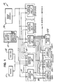
- Control system 10 may be conveniently understood as consisting of a number of subsystems, generally indicated by the dashed lines.
- Section controllers 150-1, 150-2, ..., 150-N comprise the real-time, "timing event" portion of the system, including a plurality of individual section controllers typically of the type disclosed in European Patent Specification No. 0 117 075.
- Each of section controllers 150 is assigned to a different section of an n-section glassware forming machine, typically an "I.S. forming machine" and has a terminal 140 ( Figure 3) associated therewith.
- Section controllers 150 and Machine controller 130 receive timing pulses from Timing Pulse Generator 170, to synchronise the operation of the various sections.
- the phased operation of each section is determined by a program within each controller 150 which offsets its respective starting point by a predetermined amount from the synchronising pulse.
- Each Section controller 150 generates a group of "timing drum” outputs defining the respective times within that section's operating cycle when various mechanisms are to be actuated or deactuated, or other actions are to be taken. As shown in Figure 1, these outputs may be routed directly to valve blocks 470 or other interfacing devices as is typical in the prior art, or may be transmitted to individual "mechanism controllers" 200-1, 450-1, 460-1. for that section.
- section controllers 150 may be supplied in a format analogous to conventional timing systems for I.S. machines, and a given I.S. machine may combine distributed processing of some section mechanisms with conventional "electronic timing drum” control of other mechanisms.
- the machine controller 130 and Supervisor Controller 180 comprise the "non-real-time" portion of system 10. Controller 130 supplies mechanism-specific timing set-up information, ("set-up parameters") during both initial set-up and while running the system. Machine controller 130 includes a resident program to allow it to support the functioning of a variety of mechanism controllers.
- Supervisor controller 180 supports operator communication via a machine terminal 100, printer 111, tape unit (mass storage device) 112, or other peripheral devices. Supervisor controller 180 communicates with the machine controller 130 and with the section controllers 150 via bidirectional communications links 181, 182 to deliver parameters entered by the user at terminal 110 or from mass storage unit 112, and to enable the printout and display of data.
- supervisor controller 180 communicates with the machine controller 130 and with the section controllers 150 via bidirectional communications links 181, 182 to deliver parameters entered by the user at terminal 110 or from mass storage unit 112, and to enable the printout and display of data.
- a set of mechanism controllers 200-1, 450-1, 460-1 are shown for section 1.
- the mechanism controllers communicate with machine controller 130 via bidirectional data link 135.
- Data link 135 passes set-up parameter signals from the machine controller 130 to the mechanism controllers, e.g. to download parameters entered at terminal 110.
- Data link 135 also transmits mechanism controller status signals from the mechanism controllers to machine controller 130, such as alarms, information about the mechanism environment, etc.
- data link 135 comprises an asynchronous multidrop data line. This mode of transmission simplifies wiring, interconnecting, and installation.
- each of the various mechanism controllers for a given section are physically associated with the mechanism which it is designed to control -- e.g. pushout controller 200 ( Figure 5).
- the offending part may be easily removed and replaced.
- control architecture of the invention provides many of the well known advantages of distributed control.
- the control of each mechanism may be adjusted individually and dynamically, and the controlling processes for each mechanism's actions or motions are easily programmed or changed.
- Figure 1 illustrates the general functional interrelationship between various components of control system 10, and that the block make-up of such system does not necessarily identify discrete hardware modules.
- a single section controller 150 may be provided for a plurality of machine sections, such controller including means for distinguishing timing outputs for different section.
- the machine controller 130 and supervisor controller 180 may comprise a single computer, and the machine terminal 110 may be integral with the supervisor controller or the combined supervisor/machine controller.
- the mechanism controller may consist of a master controller to control principal mechanism actions, and subservient controller to control a dependent subsystem of the mechanism.
- FIGs 3-8 illustrate a particular embodiment of a dedicated mechanism control system 100 embodying the universal controller architecture of Figure 1, for controlling a plurality of pushout assemblies.
- Figure 5 shows a pushout assembly 50 in accordance with U.S. Patent Specification No. 4 557 746. The following explanation of the operation of pushout 50 provides a background for a discussion of the dedicated pushout controller 200.
- Controller 200 is shown here packaged as a single printed circuit card plugged into an STD bus compatible backpane for convenient installation and maintenance and having a power source 205.
- Pushout 50 relies upon a combination of pneumatic and electrical power -- pneumatically powered pushout/return and extend/retract functions (controlled via solenoid valves), and an electrically controlled pushout profile.
- air Prior to the start of pushout, air is directed to the underside of the piston 71 in rotary actuator 70, upward movement of piston 71 being prevented by nut 73 on lead screw 75.
- a source of "pocket air” (not shown) has been turned on to assist the nesting of a container in pusher cylinder fingers 83.
- stepper motor 60 begins to rotate at a rate determined by a pushout profile 480 ("pushout cam"), Nut 73 moves up lead screw 75, allowing piston 71 to move.
- a helical splined shaft 78 is fixed to the upper part of piston 71, and engages a helical splined nut (not shown), so that as the shaft 78 passes through the nut it causes the nut to rotate. This rotation is transferred to pusher cylinder 80, thus controlling the sweepout profile 410 ( Figure 6F).
- a solenoid valve (not shown in Figure 5) switches and retracts the pusher cylinder finger 83, and when this mechanism returns the valve switches again to extend finger 83 over dead plate 81.
- Another solenoid valve (not shown) switches to turn off the supply of pocket air prior to completion of sweepout.
- Stepper motor 60 is reversed, returning nut 73 to its "home position" (illustrated by 420 Figure 6F), where it actuates a proximity sensor 65 to signal completion of the pushout cycle.
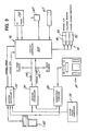
- FIG. 3 schematically illustrates at 90 various electronic control elements which act in concert with a given pushout controller 200 for controlling the electrical and pneumatic functions of a given pushout 50.
- Pushout Controller 200 communicates with Machine controller 130 by a serial multi-drop communications line 132, which is also connected to individual pushout controllers for other sections (not shown), providing asynchronous machine data transmission at 300 baud. All pushout controllers simultaneously receive non-time-critical data common to the whole I.S. machine; there are also individual broadcasts of pushout "cam” profiles.
- Alarm line 134 illustratively 24 VDC, transmits error messages from the various pushout controllers 200 to machine controller 130, for example to request rebroadcast of information via serial line 132.
- section controllers 150 takes the form disclosed in the aforementioned European Patent Specification No. 0 117 075.
- the Section controller 150 for section N provides a pair of 24 VDC pulse outputs to Pushout Controller 200 to actuate the deactuate time critical pushout functions.
- the first of these signals is the pocket air signal 300 ( Figure 6A). Its rising edge signals pushout controller to turn on pocket air -- i.e. actuate pocket air solenoid valve 91.
- the width of pulse 300 is then measured and used to calculate when to deactuate pocket air solenoid 91 after rotary actuator 70 of pushout 50 has transversed an indicated number of degrees of arcuate motion.
- the second, "pushout start” signal 310 is interpreted similarly, actuating solenoid 93 and initiating rotation of rotary actuator 70 ( Figure 5) on its rising edge, and retracting fingers 83 by deactuating solenoid 95 after a calculated number of degrees based on the width of pulse 310. Details of the control algorithm are explained below.
- pocket air solenoid valve 91 is a two way valve which turns pocket air on when energised;
- cylinder rotate solenoid valve 93 is a four way valve which is deenergised when the pusher cylinder 70 is in its home position; and
- extend/retract solenoid valve is a four way valve which when energised extends fingers 83.
- Timing pulse generator 170 provides a machine synchronisation signal once per machine cycle, to Section controller 150 and Machine controller 130.
- Machine controller 130 measures the time between pulses over a series of consecutive pulses, and recognises machine synchronisation if the pulses are within a valid machine cycle range, and the times between rising edges remain within a permitted variation. If timing signal 170 is lost after synchronisation, the pusher timing cycle will continue to run at the last measured cycle time. If the signal returns when controller 200 is in pseudo-synchronisation, Machine controller 130 measures the new pulse train and re-synchronises based on the new signal. As long as the time between rising edges changes by less than the permitted variation, the section controllers 150 and pushout controllers 200 remain synchronised.
- the operator may define a pusher timing cycle by entering a cycle timing in Machine Terminal 110.
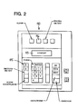
- Supervisor Controller 180 supports operator communication with machine terminal 110 (as well as possibly with other peripheral devices, such as the printer 111 and mass storage unit 112 shown in Figure 1).
- machine terminal 110 includes a two line display 113 which displays system messages and prompts.
- the keyboard 115 consists of various numeric and function keys.
- the DO key causes a selected action to be taken; the NEXT key displays the next node or sub-node title of the menu screens; EXIT returns to the first node; JOG UP and JOG DOWN change the current displayed numeric entry by a constant amount; ENTER enters the current displayed numeric information into the database of Supervisor Controller 180; CLEAR clears information just entered without changing controller values; and Section/Event allows access to a Section controller 150.
- Machine terminal 110 is used both to enter initial parameters to be downloaded into pushout controller 200, and to modify these parameters (possibly during system operation).
- Machine terminal 110 is adapted to operator supervision of multiple mechanism controller by including an appropriate set of menu screens for each mechanism controller. Menu screens may also be provided for machine components interfaced via valve block 470 ( Figure 1).
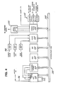
- FIG. 4 shows in block diagrammatic form the various functional elements of the dedicated pushout controller 200.
- pusher controller comprises an integrally mounted circuit card which houses a microprocessor, a unipolar chopping stepper motor drive, and other input/output conditioning circuitry.
- CPU 210 handles serial communication with Machine controller 130, and controls the operation of the other microprocessor elements in accordance with a control program stored in ROM 215.
- CPU 210 comprises an 8085 AH microprocessor of Intel Corporation. Serial communication is handled via a differential line receiver (not shown) using the 8085 SID input line.
- Counter/Timer circuit 213 is connected to the CPU's data/address bus 240.
- C/T 213 contains three independent programmable counters, the inputs of which are connected to the clock outputs of CPU 210, with the counter/timer outputs connected to the CPU's interrupt inputs.
- C/T 213 is used for communications synchronisation, CPU timing, and motor step timing.
- RAM 218 stores the current pusher cam profile and acts as a scratch pad memory for CPU 210.
- RAM 218 comprises a lK ⁇ 8 bit static random access memory integrated circuit.
- Input port 220 also connected to address/data bus 240, monitors the status of home sensor 65 ( Figure 5), and receives the pusher start signal and pocket air signal from Section controller 150.
- the pushout controller 200 includes input signal conditioning circuitry 225, for DC level-translation, isolation, filtering, and noise rejection.
- An opto-isolator circuit 225 as illustrated in Figure 9 may be used to provide both electrical isolation and level translation (24 VDC input to 5 VDC CPU signal level).
- Resistor R2 is selected so that approximately 12 VDC must be present at the input before the microprocessor detects a change at input port 220.
- Resistor Rl act as a low pass filter to reject high frequency noise.
- Output latch 230 is connected to CPU 210 via the address/data bus 240.
- Latches 230 provide four bit parallel output ports under the control of CPU 210.
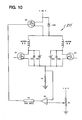
- pusher controller 200 employs a unipolar chopping stepper motor circuit 235 of the type shown in Figure 10 for driving the stepper motor 60 of Figure 5.
- Figure 10 shows one half of the drive circuit.
- N-channel phase switches e.g. driver transistor Q1 and diodes CR1 and CR2
- P-channel FET Q3 is therefore on at this point.
- the discrete coil winding for phase A (for example) is energised by changing the gate voltage from 0 VDC to 12 VDC, allowing current to flow through Q1 and Q3.
- Figure 11 illustrates an advantageous output driver circuit 250 of the type used to actuate and deactuate the various solenoid valves 91, 93, and 95 (Figure 3).
- Output driver 250 converts the microprocessor commands, in the form of 5 VDC signals, to 24 VDC drive signals for the pusher solenoids (up to 1 ampere inductive load).
- U4 comprises an opto-isolator which is driven by the 5 VDC signal from output latch 230 ( Figure 4).Turning on U4 allows current to flow through R7 and R8, thereby turning on Q4 and energising the load. Diode CR6 protects switch Q4 from inductive loads.
- Table 1 lists in order the displays which are associated with the menu-driven software and are used by terminal 110 for inputting and displaying various data for the pushout control system. Menu selection relies in particular on three keys of terminal 110 - the DO key to execute the currently displayed item, the NEXT key for displaying the next item in the menu, and the PREVIOUS key for displaying the previous menu item.
- the user selects various required parameters including the desired cam profile. These may be later modified during operation of pushouts 50 for fine-tuning.
- the master offset angle represents the number of machine degrees offset from the sync signal of the pushout cycle for each section, which may be adjusted to maximise the container dead plate time. "Pocket air on” gives the number of machine degrees before the start of pushout, while “pocket air off” gives the number of pushout degrees (arcuate degrees) upon which pocket air is turned off; these may be adapted to control the "nesting" and stability of containers held by fingers 83 ( Figure 5).
- Cam Profile Select (Item B1) enables the user to select the part of number of a desired pushout cam (stepper motor drive profile) from a profile chart.
- Cam Speed (C1) permits operator variations of pushout speed within certain limits, and may be used to adjust the release of container from the pusher fingers 83 to an outfeed conveyor.
- Pushout Start (D1) permits fine adjustment of pushout firing order, while Retract Angle (D2) corrects various mechanical problems associated with mistimed finger retract.
- the pushout sections may be started individually by releasing the maintenance stop button 116, selecting the appropriate section under the "Section Status" menu item El (Table 1), and turning on Machine controller 130. This commences down loading of data to pushout controller 200.
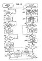
- FIG. 7 is a block schematic diagram of the startup routine of the pusher control program in ROM 215 ( Figure 4).
- the pulse width of the pocket air signal is used to communicate the number of degrees of arcuate motion through which the pusher
- DELTAST is measured between the first and second pusher start pulses, and between the second and third, at 368. These measurements are tested at 371, 373 to determine whether the cycle time exceeds a required minimum MINDEL, and whether the successive DELTAST measurements are substantially equal ( ⁇ 2%). If these tests are passed, the program calculates and stores S1 and S2 according to the above formula (step 376), and scales the entered cam profile according to the machine cycle time (DELTAST) (step 378). The microprocessor then instructs the motor 60 to rotate nut 73 to its home position (step 380), and when this is verified at 381, enters the operating loop (383).
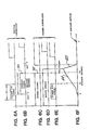
- Figure 8 sets forth the operating steps which are repeated at each pushout control cycle (see the timing diagrams of Figures 6A-6F).
- the pocket air solenoid is energised upon detecting the rising edge of the "pocket air” signal.
- the cylinder rotate valve is energised in anticipation of the next "pusher start” signal.
- the microcomputer measures and stores the current DELTAST value - i.e. the time between the current start signal's rising edge and the last one received and stored (step 391).
- the loop comprising steps 392-397 rotates the pusher cylinder according to the newly scaled cam profile.
- the pushout rotates the proper number of degrees, pocket air is turned off (at motor step S1), and the fingers are retracted (at motor step S2).
- the microprocessor switches the cylinder rotate solenoid to allow the pusher cylinder 70 to return (step 398), then (after an interval) (100 ms. (step 399)) instructs the motor to return the nut to its home position (steps 400 and 403).
- the extend/retract solenoid 95 is energised to extend fingers 83 (step 405).
- step 406 The "pocket air” and “pusher start” signals are again measured (step 406), to calculate and store S1 and S2, and the cam is rescaled for the last-measured value of DELTAST (step 407). This prepares the system for the next cycle.
- the dedicated pushout control system discussed above illustrates the basic principals of the invention in a particular system architecture ( Figure 3), dedicated controller design ( Figure 4), and suitable set-up and operating procedures. These may be appropriately extended to systems combining the universal controller architecture of Figure 1, and similar architectures, with other types of dedicated mechanism controller.
- the pushout controller 200 has been illustrated in the context of a given set of inputs and outputs to mechanism controller 200 -- solenoid valve driver and motor driver outputs, and home position sensor inputs.
- mechanism controllers may be applied to a wide variety of digital, analog, and serial inputs and outputs (including both control and communication devices).
- Illustrative control and communication devices include push buttons, pilot lights, solenoid valves, motors, control valves, process control transmitters (for temperature, pressure, etc.), keyboards, alphanumeric displays, etc.
- Figure 12 illustrates a mechanism controller 450 dedicated to the control of a takeout assembly of a glassware forming machine.
- Takeout controller 450 includes a serial line 451 which communicates with the machine controller, and a series of timing signal lines 452-454 which transmit signals from a section controller (not shown).
- lines 452-454 transmit Takeout Out, Takeout In, and Tongs Close signals, respectively, for real time control of the primary takeout actions.
- the controller 450 controls the takeout by controlling a solenoid valve 456.
- the actual motion profile of the takeout arm is governed by takeout controller 450, by means of parameter or table data downloaded via serial line 451.
- An appropriate program for the takeout arm trajectory could take into account predetermined dimensions and other physical characteristics of the glassware article for a given job, such data being entered by the user art machine terminal 110 ( Figure 1).
- Takeout controller 450 can also monitor its own status and the status of the controller takeout assembly, including such information as motor current, air pressure, and mechanism failure modes. Such information could be obtained from one or more sensors 457 and used to diagnose or anticipate operational problems. For example, a deviation of the motor current (measured at 458) from its normal range might indicate mechanism wear or a binding problem before a failure actually occurs. Other alarms might be reported via alarm line 455 after the mechanism has failed. Such information would help the operator determine the cause of the malfunction and take appropriate corrective action.
- FIG. 13 illustrates still another mechanism controller 460, for an invert assembly.
- Real time control signals on lines 462, 463 include invert and revert signals.
- Controller 460 also has a serial line 461, an alarm line 465, and sensors 467 measuring, for example motor current at 468.
- the controller 460 controls a solenoid valve 466 and would operate similarly to takeout controller 450, discussed above.
Landscapes
- Engineering & Computer Science (AREA)
- Chemical & Material Sciences (AREA)
- Physics & Mathematics (AREA)
- General Physics & Mathematics (AREA)
- Automation & Control Theory (AREA)
- Mechanical Engineering (AREA)
- Manufacturing & Machinery (AREA)
- Materials Engineering (AREA)
- Organic Chemistry (AREA)
- Programmable Controllers (AREA)
- Control Of Conveyors (AREA)
Applications Claiming Priority (2)
| Application Number | Priority Date | Filing Date | Title |
|---|---|---|---|
| US06/775,454 US4685947A (en) | 1985-09-12 | 1985-09-12 | Glassware forming apparatus with distributed control and method of operation |
| US775454 | 2001-02-01 |
Publications (3)
| Publication Number | Publication Date |
|---|---|
| EP0215633A2 true EP0215633A2 (de) | 1987-03-25 |
| EP0215633A3 EP0215633A3 (en) | 1989-03-15 |
| EP0215633B1 EP0215633B1 (de) | 1993-08-11 |
Family
ID=25104480
Family Applications (1)
| Application Number | Title | Priority Date | Filing Date |
|---|---|---|---|
| EP86306957A Expired - Lifetime EP0215633B1 (de) | 1985-09-12 | 1986-09-10 | Elektronische Steuervorrichtung für eine Glaswarenbearbeitungsmaschine |
Country Status (7)
| Country | Link |
|---|---|
| US (2) | US4685947A (de) |
| EP (1) | EP0215633B1 (de) |
| AU (1) | AU586701B2 (de) |
| BR (1) | BR8604445A (de) |
| DE (1) | DE3688867T2 (de) |
| IN (1) | IN170224B (de) |
| MX (1) | MX165692B (de) |
Cited By (7)
| Publication number | Priority date | Publication date | Assignee | Title |
|---|---|---|---|---|
| FR2647921A1 (fr) * | 1989-06-03 | 1990-12-07 | Isowa Industry Co | Procede de commande decentralisee pour chaine de machines a onduler |
| EP0377331A3 (de) * | 1988-12-30 | 1993-06-09 | Pitney Bowes Inc. | Meldungsaustausch für eine mehrfache Bearbeitungsstation |
| EP0376738A3 (de) * | 1988-12-30 | 1993-06-09 | Pitney Bowes Inc. | Kommunikation in Dualbetriebsart |
| ES2073988A1 (es) * | 1993-04-06 | 1995-08-16 | Avacon Sa | Sistema computerizado de accionamiento rotativo para la movilizacion sincronizada de diferentes productos, en especial envases de vidrio |
| WO1997040430A1 (de) * | 1996-04-23 | 1997-10-30 | Robert Bosch Gmbh | Steuergerät, insbesondere kraftfahrzeugsteuergerät |
| GB2328521A (en) * | 1997-05-16 | 1999-02-24 | Emhart Glass Mach Invest | Programmable 'electronic clutch' for an I. S. machine |
| CN104460407A (zh) * | 2014-10-15 | 2015-03-25 | 北京英博电气股份有限公司 | 一种通过短接端口来实现触摸屏一屏多机控制的控制系统 |
Families Citing this family (38)
| Publication number | Priority date | Publication date | Assignee | Title |
|---|---|---|---|---|
| US4825376A (en) * | 1986-04-17 | 1989-04-25 | Glasstech International L.P. | Controller for glass sheet processing system |
| US4858101A (en) * | 1987-08-26 | 1989-08-15 | Allen-Bradley Company, Inc. | Programmable controller with parallel processors |
| US5210821A (en) * | 1988-03-28 | 1993-05-11 | Nissan Motor Company | Control for a group of robots |
| US4945933A (en) * | 1988-04-11 | 1990-08-07 | Serv-Tech, Inc. | Liquid circulator useful for dispersing sediment contained in a storage tank |
| US5125499A (en) * | 1989-10-27 | 1992-06-30 | Vhc, Ltd. | Article transfer mechanism |
| US5652490A (en) * | 1992-03-11 | 1997-07-29 | Emhart Glass Machinery Investments Inc. | Control system for glassware forming machine |
| US5444861A (en) * | 1992-06-01 | 1995-08-22 | United Technologies Corporation | System for downloading software |
| US5425794A (en) * | 1992-07-31 | 1995-06-20 | Emhart Glass Machinery Investments Inc. | Pneumatic position controller for I.S. machine mechanism |
| US5271756A (en) * | 1992-12-18 | 1993-12-21 | Emhart Glass Machinery Investments Inc. | Machine for forming glass containers |
| AU665468B2 (en) * | 1992-12-18 | 1996-01-04 | Emhart Glass S.A. | Glass container forming machine control |
| US5358541A (en) * | 1993-01-08 | 1994-10-25 | The Boc Group, Inc. | Forehearth temperature control system |
| JP2963299B2 (ja) * | 1993-03-31 | 1999-10-18 | 三菱電機株式会社 | プログラマブルコントローラの周辺装置、及び内部情報設定方法 |
| US5571067A (en) * | 1993-11-19 | 1996-11-05 | Ranpak Corp. | Cushioning conversion machine including a length measuring device |
| US5580366A (en) * | 1994-04-29 | 1996-12-03 | Owens-Brockway Glass Container Inc. | Automated glassware manufacture controller |
| US6524230B1 (en) * | 1994-07-22 | 2003-02-25 | Ranpak Corp. | Packing material product and method and apparatus for making, monitoring and controlling the same |
| US5897478A (en) | 1994-07-22 | 1999-04-27 | Ranpak Corp. | Cushioning conversion machine and method using encoded stock material |
| DE776760T1 (de) * | 1994-07-22 | 1997-11-20 | Ranpak Corp., Concord Township, Ohio | Polsterumwandlungsmaschine |
| US5609663A (en) * | 1994-09-06 | 1997-03-11 | Emhart Glass Machinery Investments Inc. | Glass or plastic container manufacturing system |
| US5545244A (en) * | 1994-12-13 | 1996-08-13 | Emhart Inc. | Control for glass forming machine |
| US5846282A (en) * | 1997-11-06 | 1998-12-08 | Emhart Glass Machinery Investments Inc. | Invert and neck ring holder mechanism for an I.S. machine |
| US5843201A (en) * | 1997-11-06 | 1998-12-01 | Emhart Glass Machinery Investments Inc. | Invert and neck ring holder mechanism for an I.S. machine |
| US5895513A (en) * | 1997-11-06 | 1999-04-20 | Emhart Glass Machinery Investments Inc. | Takeout mechanism for an I.S. machine |
| US6269662B1 (en) * | 1999-03-05 | 2001-08-07 | Emhart Glass S.A. | Pneumatic machine control unit for an I.S. machine |
| US6367287B1 (en) | 1999-04-13 | 2002-04-09 | Owens-Brockway Glass Container Inc. | Two-axis motion of take-out tongs in an individual section glassware forming machine |
| IT1320798B1 (it) * | 2000-08-08 | 2003-12-10 | Bottero Spa | Sistema di controllo per una macchina per la fabbricazione di articolidi vetro cavo. |
| ITTO20001215A1 (it) * | 2000-12-22 | 2002-06-22 | Bottero Spa | Metodo per la impostazione di operazioni in una linea per la fabbricazione di articoli di vetro cavo. |
| DE10140271A1 (de) * | 2001-08-16 | 2003-03-06 | Hermann Heye I I | Elektronische Steuerung für Glasformmaschinen |
| ITTO20020023A1 (it) * | 2002-01-08 | 2003-07-08 | Bottero Spa | Sistema di controllo temporizzazione in una linea per la fabbricazione di articoli di vetro cavo. |
| DE60234828D1 (de) | 2002-09-03 | 2010-02-04 | Futronic Gmbh | Modulares Steuerungssystem für eine Glasformmaschine |
| US7017373B2 (en) * | 2002-09-03 | 2006-03-28 | Owens-Brockway Glass Container Inc. | Glassware forming machine control system |
| CA2504124C (en) * | 2002-11-01 | 2013-01-08 | Ranpak Corp. | Packaging system with volume measurement |
| AU2003219539A1 (en) * | 2003-03-18 | 2004-10-11 | T.E.R Tecno Elettrica Ravasi S.R.L. | Integrated apparatus for use in industrial machinery |
| US7117715B2 (en) * | 2004-07-09 | 2006-10-10 | Owens-Brockway Glass Container Inc. | Servo mechanism test stand |
| CN100449441C (zh) * | 2005-12-27 | 2009-01-07 | 山东三金玻璃机械股份有限公司 | 制瓶机生产线集成智能控制系统 |
| WO2011063143A1 (en) * | 2009-11-18 | 2011-05-26 | Marion Glass Equipment And Technology Company Inc. | Drive system |
| JP6969455B2 (ja) * | 2018-03-13 | 2021-11-24 | オムロン株式会社 | 制御装置、制御システム、制御方法、および、制御プログラム |
| CN114829308A (zh) | 2019-06-26 | 2022-07-29 | Vitro可变资本股份有限公司 | 用于玻璃器皿成形机的旋转线性机构 |
| CN111240245B (zh) * | 2020-01-20 | 2021-07-23 | 湖北三江航天红峰控制有限公司 | 一种伺服系统时序控制电路及方法 |
Family Cites Families (12)
| Publication number | Priority date | Publication date | Assignee | Title |
|---|---|---|---|---|
| US3905793A (en) * | 1974-10-21 | 1975-09-16 | Emhart Corp | Computer control for glassware forming machine |
| US4247317A (en) * | 1978-04-20 | 1981-01-27 | Ball Corporation | Glassware forming machine computer-ram controller system |
| GB2022870B (en) * | 1978-05-31 | 1982-12-22 | Hawker Siddeley Dynamics Eng | Computer control system |
| MX147265A (es) * | 1979-12-14 | 1982-10-29 | Gen Sattery Corp | Mejoras a un circuito de carga de baterias |
| US4313750A (en) * | 1980-09-12 | 1982-02-02 | Css International Corporation | Electronically controlled robot for handling glassware |
| US4369052A (en) * | 1981-03-19 | 1983-01-18 | Owens-Illinois, Inc. | Forming supervisory control means for glassware forming machines |
| US4427431A (en) * | 1981-03-30 | 1984-01-24 | Owens-Illinois, Inc. | Electronic control of a glass forming machine |
| US4459146A (en) * | 1982-08-18 | 1984-07-10 | Owens-Illinois, Inc. | Electronic control system in a glassware forming machine |
| AU565565B2 (en) * | 1983-01-26 | 1987-09-17 | Emhart Glass S.A. | Programmable control system for glassware forming machines |
| US4529429A (en) * | 1983-05-06 | 1985-07-16 | Ball Corporation | Digital glass forming machine |
| MX153641A (es) * | 1983-05-19 | 1986-10-14 | Vitro Tec Fideicomiso | Mejoras en controlador automatico para maquinas formadoras de articulos de vidrio |
| US4548637A (en) * | 1984-08-30 | 1985-10-22 | Owens-Illinois, Inc. | Servo-control of machine motions in manufacture of glass containers |
-
1985
- 1985-09-12 US US06/775,454 patent/US4685947A/en not_active Expired - Lifetime
-
1986
- 1986-08-20 IN IN755/DEL/86A patent/IN170224B/en unknown
- 1986-09-10 DE DE86306957T patent/DE3688867T2/de not_active Expired - Lifetime
- 1986-09-10 EP EP86306957A patent/EP0215633B1/de not_active Expired - Lifetime
- 1986-09-11 AU AU62618/86A patent/AU586701B2/en not_active Expired
- 1986-09-12 MX MX003721A patent/MX165692B/es unknown
- 1986-09-12 BR BR8604445A patent/BR8604445A/pt not_active Application Discontinuation
- 1986-10-21 US US06/921,554 patent/US4705552A/en not_active Expired - Lifetime
Cited By (9)
| Publication number | Priority date | Publication date | Assignee | Title |
|---|---|---|---|---|
| EP0377331A3 (de) * | 1988-12-30 | 1993-06-09 | Pitney Bowes Inc. | Meldungsaustausch für eine mehrfache Bearbeitungsstation |
| EP0376738A3 (de) * | 1988-12-30 | 1993-06-09 | Pitney Bowes Inc. | Kommunikation in Dualbetriebsart |
| FR2647921A1 (fr) * | 1989-06-03 | 1990-12-07 | Isowa Industry Co | Procede de commande decentralisee pour chaine de machines a onduler |
| ES2073988A1 (es) * | 1993-04-06 | 1995-08-16 | Avacon Sa | Sistema computerizado de accionamiento rotativo para la movilizacion sincronizada de diferentes productos, en especial envases de vidrio |
| WO1997040430A1 (de) * | 1996-04-23 | 1997-10-30 | Robert Bosch Gmbh | Steuergerät, insbesondere kraftfahrzeugsteuergerät |
| US6104971A (en) * | 1996-04-23 | 2000-08-15 | Robert Bosch Gmbh | Controller, in particular motor vehicle controller |
| GB2328521A (en) * | 1997-05-16 | 1999-02-24 | Emhart Glass Mach Invest | Programmable 'electronic clutch' for an I. S. machine |
| GB2328521B (en) * | 1997-05-16 | 2001-10-24 | Emhart Glass Machinery Invest | Programmable electronic clutch for I.S.machine |
| CN104460407A (zh) * | 2014-10-15 | 2015-03-25 | 北京英博电气股份有限公司 | 一种通过短接端口来实现触摸屏一屏多机控制的控制系统 |
Also Published As
| Publication number | Publication date |
|---|---|
| DE3688867T2 (de) | 1994-03-10 |
| US4685947A (en) | 1987-08-11 |
| DE3688867D1 (de) | 1993-09-16 |
| MX165692B (es) | 1992-12-01 |
| IN170224B (de) | 1992-02-29 |
| US4705552A (en) | 1987-11-10 |
| BR8604445A (pt) | 1987-05-12 |
| EP0215633A3 (en) | 1989-03-15 |
| AU6261886A (en) | 1987-03-19 |
| EP0215633B1 (de) | 1993-08-11 |
| AU586701B2 (en) | 1989-07-20 |
Similar Documents
| Publication | Publication Date | Title |
|---|---|---|
| EP0215633B1 (de) | Elektronische Steuervorrichtung für eine Glaswarenbearbeitungsmaschine | |
| US4152134A (en) | Electronic control system for an individual section glassware forming machine | |
| US4247317A (en) | Glassware forming machine computer-ram controller system | |
| US5345389A (en) | Electronic controller for a glassware forming machine | |
| CA1209677A (en) | Electronic control system in a glassware forming machine | |
| EP0603011B1 (de) | Steuerung einer Maschine zum Herstellen von Glascontainern | |
| CA1235215A (en) | Digital glass forming machine | |
| JPS6125661B2 (de) | ||
| EP0048133B2 (de) | Elektronische Handhabung von Glasgegenständen | |
| EP0100239B1 (de) | Verfahren und Vorrichtung zur Regelung der Zuführung von Glasposten zu einer Glasformmaschine | |
| GB2178421A (en) | Electronic glass feeder plunger operating mechanism | |
| US4547211A (en) | Control of a glassware forming machine | |
| EP0117075B1 (de) | Programmierbares Steuersystem für Glasformmaschinen | |
| US4608074A (en) | Gob distributor | |
| CN86107810A (zh) | 分布控制式玻璃器皿成型装置 | |
| CA1125516A (en) | Timing value dwell reversal protection for glassware forming machine electronic controls | |
| EP1216966B1 (de) | Verfahren zum einstellen von betriebsmassnahmen bei der herstellung von hohlglaswaren | |
| GB2342464A (en) | Process for operating a stepper motor controller in a sewing machine | |
| CZ19211U1 (cs) | Řídicí systém k řízení mechanismů, zejména řízení mechanismu odstávky sklářského tvarovacího stroje |
Legal Events
| Date | Code | Title | Description |
|---|---|---|---|
| PUAI | Public reference made under article 153(3) epc to a published international application that has entered the european phase |
Free format text: ORIGINAL CODE: 0009012 |
|
| AK | Designated contracting states |
Kind code of ref document: A2 Designated state(s): DE FR GB IT |
|
| PUAL | Search report despatched |
Free format text: ORIGINAL CODE: 0009013 |
|
| AK | Designated contracting states |
Kind code of ref document: A3 Designated state(s): DE FR GB IT |
|
| 17P | Request for examination filed |
Effective date: 19890828 |
|
| RAP1 | Party data changed (applicant data changed or rights of an application transferred) |
Owner name: EMHART INDUSTRIES, INC. |
|
| 17Q | First examination report despatched |
Effective date: 19910820 |
|
| RAP1 | Party data changed (applicant data changed or rights of an application transferred) |
Owner name: EMHART GLASS MACHINERY INC., |
|
| RAP1 | Party data changed (applicant data changed or rights of an application transferred) |
Owner name: EMHART GLASS MACHINERY INVESTMENTS INC. |
|
| GRAA | (expected) grant |
Free format text: ORIGINAL CODE: 0009210 |
|
| AK | Designated contracting states |
Kind code of ref document: B1 Designated state(s): DE FR GB IT |
|
| REF | Corresponds to: |
Ref document number: 3688867 Country of ref document: DE Date of ref document: 19930916 |
|
| ET | Fr: translation filed | ||
| ITF | It: translation for a ep patent filed | ||
| PLBE | No opposition filed within time limit |
Free format text: ORIGINAL CODE: 0009261 |
|
| STAA | Information on the status of an ep patent application or granted ep patent |
Free format text: STATUS: NO OPPOSITION FILED WITHIN TIME LIMIT |
|
| 26N | No opposition filed | ||
| REG | Reference to a national code |
Ref country code: FR Ref legal event code: TP |
|
| REG | Reference to a national code |
Ref country code: GB Ref legal event code: IF02 |
|
| PGFP | Annual fee paid to national office [announced via postgrant information from national office to epo] |
Ref country code: GB Payment date: 20050908 Year of fee payment: 20 |
|
| PGFP | Annual fee paid to national office [announced via postgrant information from national office to epo] |
Ref country code: FR Payment date: 20050919 Year of fee payment: 20 |
|
| PGFP | Annual fee paid to national office [announced via postgrant information from national office to epo] |
Ref country code: IT Payment date: 20050929 Year of fee payment: 20 |
|
| PGFP | Annual fee paid to national office [announced via postgrant information from national office to epo] |
Ref country code: DE Payment date: 20051031 Year of fee payment: 20 |
|
| PG25 | Lapsed in a contracting state [announced via postgrant information from national office to epo] |
Ref country code: GB Free format text: LAPSE BECAUSE OF EXPIRATION OF PROTECTION Effective date: 20060909 |
|
| REG | Reference to a national code |
Ref country code: GB Ref legal event code: PE20 |