EP0215743A2 - Vorrichtung zur Planheitsmessung und -steuerung von Walzband - Google Patents
Vorrichtung zur Planheitsmessung und -steuerung von Walzband Download PDFInfo
- Publication number
- EP0215743A2 EP0215743A2 EP86830175A EP86830175A EP0215743A2 EP 0215743 A2 EP0215743 A2 EP 0215743A2 EP 86830175 A EP86830175 A EP 86830175A EP 86830175 A EP86830175 A EP 86830175A EP 0215743 A2 EP0215743 A2 EP 0215743A2
- Authority
- EP
- European Patent Office
- Prior art keywords
- strip
- channel
- pressure
- air
- channels
- Prior art date
- Legal status (The legal status is an assumption and is not a legal conclusion. Google has not performed a legal analysis and makes no representation as to the accuracy of the status listed.)
- Granted
Links
Images


Classifications
-
- B—PERFORMING OPERATIONS; TRANSPORTING
- B21—MECHANICAL METAL-WORKING WITHOUT ESSENTIALLY REMOVING MATERIAL; PUNCHING METAL
- B21B—ROLLING OF METAL
- B21B38/00—Methods or devices for measuring, detecting or monitoring specially adapted for metal-rolling mills, e.g. position detection, inspection of the product
- B21B38/02—Methods or devices for measuring, detecting or monitoring specially adapted for metal-rolling mills, e.g. position detection, inspection of the product for measuring flatness or profile of strips
-
- B—PERFORMING OPERATIONS; TRANSPORTING
- B21—MECHANICAL METAL-WORKING WITHOUT ESSENTIALLY REMOVING MATERIAL; PUNCHING METAL
- B21B—ROLLING OF METAL
- B21B27/00—Rolls, roll alloys or roll fabrication; Lubricating, cooling or heating rolls while in use
- B21B27/06—Lubricating, cooling or heating rolls
- B21B27/10—Lubricating, cooling or heating rolls externally
- B21B2027/103—Lubricating, cooling or heating rolls externally cooling externally
Definitions
- the invention relates to shapemetering.
- a process and apparatus are disclosed for visual monitoring and continuous resultant correction of the profile and surface flatness of rolled strip, metal or otherwise, and in particular for metals which are rolled and subsequently rewound.
- the disclosure is directed principally toward mills utilized for rolling metal strip, the application clearly embraces other types of plant for the forming of non-metallic strip materials; thus, notwithstanding reference is made to rolled metal strip throughout the specification for ease of description, such reference in no sense limits the scope of the invention.
- FIG 1 the schematic representation of a rolling mill, given as an example, illustrates a metal strip 1, a pair of work rolls 2 and a relative pair of back-up rolls 3. The rolled strip is rewound onto a recoiler 4.
- the train of rolls may also incorporate idle and tensioning rolls such as those denoted 32 in fig 1 over which the strip 1 is run in order to ensure the best possible distribution of tension and constant alignment on arrival at the recoiler 4.
- the surface of the strip 1 may appear perfectly flat and free from faults or unevenness, to the naked eye; this notwithstanding, the tension to which the strip is subject, and its high speed through the mill rolls (often hundreds of metres per minute), are such that visual inspection alone cannot detect these defects, especially where small and/or localized.
- Single faults and general unevenness may be manifested in different ways, continuously or localized, occurring across the main body of the strip or near the edges alone, and may be of diverse origin.
- Such defects in rolled metal strip 1 can be attributable to errors in 'tilt' and 'crown' of the mill rolls 2 and 3, or more often, to the lack of proper distribution of cooling on these rolls (usually effected by spraying with special coolants).
- a number of rotors mounted adjacent to one another and rotatable on a stationary transverse shaft have respective cylin drical cavities filled with fluid which is pressurized to a constant value.
- Measurement of the variations in strip tension is achieved by detecting the difference in pressure of the fluid, occasioned by positive or negative shift in the strip tension transmitted to each rotor, between two opposite set points.
- Transducers are used to relay the detected information to a CPU which, having acknowledged and processed the input data in the prescribed manner, relays control signals which actuate appropriate corrective media.
- the rotor device involves notably complex construction, by reason of its comprising fixed and moving parts and pressurized-fluid seals, and of its being characterized by tight tolerance margins in embodiment; the device is thus invested with a certain structural inertia which in turn has a limiting influence on sensitivity, and which, given the complexity of the control system, does not permit of real time corrective action via the media utilized for rectifying error.
- design drawbacks are compounded further by a requirement for continual servicing and verification of the device's efficient operation, and by a marked energy consumption, which in turn signifies somewhat high outlay and running costs.
- a fundamental object of the invention disclosed is the design and embodiment of a new shapemetering process, that is, a process for detection and measurement of faults and unevenness in the shape of rolled strip, wherein the sole medium used both in the detection and measurement of such faults and in controlling the media which provide the corrective action, is a pressurized fluid, compressed air in particular, maintained at a constant input pressure and circulated between the running metal strip and the essentially fixed and flat reacting surface of the shapemeter across a succession of width increments in the strip.
- the principal object of the disclosure is embodiment of apparatus to carry the claimed shapemetering process into effect, which neither has parts in contact with the running surface of the rolled strip, nor has driven moving parts, and is thus devoid of mechanical inertia and of kinematic linkages which pick up effects induced by the running metal strip via direct contact.
- Another object of the invention is that of providing a shapemetering process and embodying relative apparatus for detection, measurement and display of faults and unevenness in rolled strip, and for control of the media utilized in correcting mill roll contour, in which a single source of energy is utilized for both metering and auxiliary purposes, namely, compressed air supplied at a constant preset pressure.
- a stretch of rolled metal sheet 1 running out from the mill rolls 2 may be thought of in theory, and represented schematically, as a number of parallel strings suspended between two straight-line supports 6 & 6', as shown in fig 2, all invested with equal tension F working in opposite directions.
- Such a representation reflects a perfectly flat stretch of metal strip 1, the imaginary strings being of equal length, and parallel one with another.
- the metal strip will be invested, in practice, with varying tension components (e.g. F1, F2 & F3) differing from string to string, which in isolation would tend to exhibit differences in length one from another (fig 3); such a condition is indicative of lack of flatness in the same stretch of strip.
- the process disclosed herein to the end of realizing the proposed objects, is illustrated schematically in fig 5, and envisages the application of a plurality of forces 8 perpendicular to the running strip 1, ranged across a succession of increments occupying the width of the strip and transverse to its path of movement.
- the single forces 8 originate from a single fluid power source 9 supplied at a constant pressure, which is compressed air in the case of the disclosure. Intensity of the single forces must be calibrated to the point of suspending the rolled metal strip, assumed perfectly flat and evenly tensioned, and referred to an adjacent surface of the apparatus SR, by selection and subsequent variation of a given pressure value at source which will depend ultimately on the type, gauge, and running speed of the rolled strip.
- the next step in the process is continuous measurement of the intensity of each single force at the axis of its point of application, an entity that is dependent upon the pressure of fluid applied to the corresponding zone of the metal strip, and upon resistance offered to such pressure by the strip, i.e. back-pressure which reflects the degree of departure from perfect flatness at such a zone.
- valve transducers VT designed to pilot the proportional opening or closing movement, according to a selected scale, of conventional valves VE supplying coolant 11 to spray nozzles 12 directed at the section or sections of the mill rolls 2 & 3 which correspond to the strip width increment or increments from where the control signal or signals will have originated.
- the plurality of forces 8 incorporated into the system will thus be matched, both in number and for position, by corresponding groups of sprays at the mill rolls.
- the same differences in pressure registering at the point of application of each force 8 can be exploited further as an input for electrical or electronic transducers TR so as to provide signals relayed to means for automatic operation and control of the whole shapemeter system, which, in the case of the conventional CPU denoted EL (fig 5) will be allotted the task of analyzing the variations detected and supplying the appropriate control signals to actuate corrective measures, for example, changing the tilt or bending force/moment of the back-up rolls 3, modifying the running speed of the strip 1 or adjusting the pressure of compressed air and/or coolant.
- the process thus described is carried into effect by apparatus which is designed for installation along the stretch of rolled strip running between the mill rolls 2 & 3 and recoiler 4, and in particular, between two idle rolls 32 the pur pose of which is to maintain the running surface of the stretch in question at a constant lie, relative to the reference surface SR of the apparatus (figs 1 & 10).
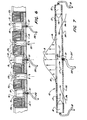
- the apparatus is comprised substantially of an essentially flat box-structure 13 extending transversely in relation to the path of movement of the strip 1, and incorporating a plurality of channels 14 disposed parallel one with another and spaced apart at a given equal distance one from the next.
- the channels 14 lie parallel to the path of movement of the strip, considered longitudinally, (fig 10) and each channel is provided with a pair of nozzles 15 mounted one at either end in direct opposition so as to produce respective jets 17 of compressed air (fig 7) that are thus in collision within the enclosure 16 formed by the channel.
- This compressed air is the sole source of fluid power for operation both of the apparatus and of its auxiliary services, and is supplied to each of the channels 14 from a single source by relative pairs of air-lines 18; the same air supply thus serves to create the plurality of forces 8 aforementioned, and to provide a proportional control medium 10 (fig 5) as already mentioned in the foregoing description.
- Each single channel 14, which exhibits a quadrangular section in a preferred embodiment, has a longitudinal opening 19 located in the side offered to the strip 1, that extends equal distance forward and rear from a dividing section 20 passing transversely through the channel as shown in fig 7.
- This dividing section 20 establishes an absolutely central collision zone for each pair of opposed jets 17 where a conversion is brought about, according to known physical principles, in which kinetic energy carried by the jets is transformed into pressure that is directed perpendicularly toward the strip 1 via the longitudinal opening 19, causing the strip to take on the essentially parabolic configuration in fig 7. Pressure thus directed at the strip reaches a maximum value when coincident with the axis 20' of the collision zone 20, and this is in fact the force 8 which is applied to the rolled strip at the central transverse axis of each opening 19.
- Each channel 14 is provided further with an outlet 21, likewise coincident with the axis of the collision zone and located at the side opposite the opening 19, which connects via a relative fluid line 22 (figs 6 & 7) with means for continuous detection and measurement of the force 8, i.e. of the pressure value and its variations, registering at axis 20'.
- the box-structure 13 also incorporates a plurality of single vents 23 disposed parallel to and in alternation with the channels 14 and aligned with the longitudinal openings, hence with the collision zones 20, which provide an escape (denoted by arrows in fig 6) for the air issuing from adjacent openings 19.
- the box-structure 13 further comprises lengths of fibrous and/or flexible material 24, say ⁇ felt or carpet, located between adjacent channels 14, which surround the vents 23 such that the surface of the vent aligns with that of the length of material (see figs 6 & 10).
- These lengths of material create a surface across which the strip 1 can ride without encountering any resistance other than a bare minimum, suspended as it is by thrust from the forces 8 aforedescribed, and serve to establish a permeable barrier offered to the streams of air escaping from the adjacent openings 19, which are broken up in order to prevent interference between one escaping stream and the next, across the apparatus.
- each channel 14 exhibits a pair of identical inlets 25 in the side opposite that incorporating the longitudinal opening 19, located one at either end inwardly from and below the respective nozzle 15; air is drawn through these inlets 25 into the channel enclosure 16 from the surrounding environment (denoted by the arrows 26 in fig 7) as a result of the depression created by the jets 17.
- the box-structure 13 is such that those sections beneath the permeable barrier material 24 and between adjacent channels 14 are boxed in to create chambers 27 in which air may circulate, as shown in fig 8.
- Such chambers 27 communicate uppermost with a respective vent 23 and are provided with air-deflection profiles 28 located one at either end; in addition, each chamber 27 communicates at either end with the two adjacent channels 14 by way of a pair of air holes 29 located in the channel side walls, each alongside a relative air-deflection profile 28.
- Each hole 29 is angled so as to complement the slant of the profile, and communicates with the inside of one end of a relative channel enclosure 16 at a point in sight of the inward-facing end of the nozzle.
- the chamber 27 provides for recirculation of air escaping from the vents 23 back into the channels at either side, as illustrated by the arrows in fig 8; recirculated air joins and integrates the streams 26 already taken in via the bottom inlets, increasing the ultimate volume of the colliding jets 17' and further enhancing balanced utilization of available energy by cutting the volume requirement at source.
- the lengths of barrier material 24 are replaced to advantage by hollow longitudinal elements 33 arranged in like manner and shaped in such a way as to create a pair of symmetrical enclosures 34 which exhibit a pear-drop profile when seen in cross section, as in fig 9.
- Each such enclosure 34 is provided with a longitudinal succession of holes 35 at the side of profile exhibiting the tighter radius, which are directed toward the longitudinal opening 19 of the respective channel 14 alongside, and with longitudinal openings 36 at the side exhibiting wider radius, which are directed toward the surface of the strip 1.
- Each pair of elements 33 creating the symmetrical pair of enclosures 34 is joined together by an interconnecting profile 37.
- a slot 38, located in this profile 37, performs exactly the same function as the vents 23 in the first embodiment described, communicating as it does with the chambers 27, air-deflection profiles 28 and air holes 29, by way of a corresponding slot 39 in the box-structure 13.
- intensity of the single applied forces 8 is measured by detecting pressure which registers through the axes 20' of the relative collision zones 20 and reflects back-pressure from the strip 1 utilizing manometers of a conventional type, served by fluid lines 22 which are connected to outlets 21 coincident with the single axes 20'.
- the manometers are ordered in an array that mirrors the tranverse succession of width increments making up the strip and corresponds to the single channels 14, providing a display wherein variations in pressure per increment are visualized in continuous fashion; being proportionate to the degree of tension with which the strip 1 is invested, such variations reflect the extent of departure from flatness, hence the term shapemeter.
- the manometers 30 are of a type utilizing a column of liquid, and are located in vertical and parallel array across the apparatus so as to provide a permanent analogical display that monitors strip shape by way of an imaginary curve 31 coinciding with the single liquid levels (fig 10), and therefore reflecting the variations in tension across the strip.
- the fluid lines 22 to the manometers are branched as shown schematically by lines 10 in fig 5, and connect with respective valve transducers VT which actuate the continuous opening and closing movement of a correspond ing number of supply valves VE controlling the flow of coolant 11, in proportional response to the differences in pressure registering through the self-same lines 22, and according to a predetermined scale.
- the coolant valves VE are of a conventional type.
- the valve transducers VT may be any one of a number of types, diaphragm for example, or hydraulically operated for preference, and must convert the pressure registering through single fluid lines 22 into mechanical or electrical power such as will open or close the coolant supply valves VE in proportion to such pressure.
- valves VT and VE Such control is brought about in real time and with no interruption other than that produced by insignificant levels of inertia in valves VT and VE; what is more, the reading requires no intermediate measure-calculate-and-respond circuitry.
- apparatus such as that described will be embodied such that the channels 14, vents 23 or slots 39, display manometers 30 and valves VT and VE correspond in number to the pairs of conventional grouped spray nozzles 12 installed along the mill rolls 2 and 3, and occupy corresponding transverse positions across the width of the strip 1.
- Apparatus according to the invention thus realizes the stated objects, permitting of continuous and automatic selective correction of thermal conditions in the mill rolls 2 & 3 in real time, and continuous visualization of the flatness of the strip 1 such as will furnish the mill operator with an indication as to when corrective measures should be implemented, e.g. modification of the tilt and/or the crown of the mill rolls 2 & 3.
- the branched fluid lines 22 may also be connected to relative electric/electronic transducers TR (fig 5) in order to provide a continuous input for a CPU, denoted EL in fig 5, which will program and run the complete system automatically, as aforementioned.
- FIG. 10 The perspective view of fig 10 shows apparatus of the type described where, in the interests of simplicity, means for adjusting and positioning the box-structure are omitted, being common knowledge to one having skill in the art; the box-structure 13 must in fact be placed such that its reference surface SR lies adjacent to the running metal strip 1.
- figs 7, 8 & 9 do not show means for micrometric positioning of the nozzles 15 and for adjustment of the colliding jets 17 & 17' with respect to the collision zone 20, which are similarly commonplace to one skilled in the art.
Landscapes
- Engineering & Computer Science (AREA)
- Mechanical Engineering (AREA)
- Force Measurement Appropriate To Specific Purposes (AREA)
- Length Measuring Devices With Unspecified Measuring Means (AREA)
- Measuring Arrangements Characterized By The Use Of Fluids (AREA)
- Coating With Molten Metal (AREA)
- Straightening Metal Sheet-Like Bodies (AREA)
- Length Measuring Devices By Optical Means (AREA)
Priority Applications (1)
| Application Number | Priority Date | Filing Date | Title |
|---|---|---|---|
| AT86830175T ATE70472T1 (de) | 1985-09-20 | 1986-06-19 | Vorrichtung zur planheitsmessung und -steuerung von walzband. |
Applications Claiming Priority (2)
| Application Number | Priority Date | Filing Date | Title |
|---|---|---|---|
| IT48579/85A IT1182868B (it) | 1985-09-20 | 1985-09-20 | Procedimento ed apparecchiatura per il controllo e/o correzione continua del profilo e planarita' di nastri metallici e simili |
| IT4857985 | 1985-09-20 |
Publications (3)
| Publication Number | Publication Date |
|---|---|
| EP0215743A2 true EP0215743A2 (de) | 1987-03-25 |
| EP0215743A3 EP0215743A3 (en) | 1989-02-22 |
| EP0215743B1 EP0215743B1 (de) | 1991-12-18 |
Family
ID=11267439
Family Applications (1)
| Application Number | Title | Priority Date | Filing Date |
|---|---|---|---|
| EP86830175A Expired EP0215743B1 (de) | 1985-09-20 | 1986-06-19 | Vorrichtung zur Planheitsmessung und -steuerung von Walzband |
Country Status (8)
| Country | Link |
|---|---|
| US (1) | US4809527A (de) |
| EP (1) | EP0215743B1 (de) |
| JP (1) | JPS62110109A (de) |
| AT (1) | ATE70472T1 (de) |
| CA (1) | CA1274992A (de) |
| DE (1) | DE3682989D1 (de) |
| ES (1) | ES2001497A6 (de) |
| IT (1) | IT1182868B (de) |
Cited By (1)
| Publication number | Priority date | Publication date | Assignee | Title |
|---|---|---|---|---|
| WO1994000255A1 (en) * | 1992-06-22 | 1994-01-06 | Asea Brown Boveri Ab | Flatness control in the rolling of strip |
Families Citing this family (14)
| Publication number | Priority date | Publication date | Assignee | Title |
|---|---|---|---|---|
| US5315861A (en) * | 1992-10-19 | 1994-05-31 | General Electric Company | Method and apparatus for inspection of open face honeycomb structures |
| US5275489A (en) * | 1992-10-19 | 1994-01-04 | General Electric Company | Apparatus and method for inspecting an open-face cell structure bonded to a substrate |
| DE19511801A1 (de) * | 1995-03-30 | 1996-10-02 | Schloemann Siemag Ag | Verfahren und Vorrichtung zur Dickenvorsteuerung beim Folienwalzen |
| US5901591A (en) * | 1996-04-29 | 1999-05-11 | Tippins Incorporated | Pinch roll shapemetering apparatus |
| FR2815705B1 (fr) * | 2000-10-20 | 2003-04-18 | Val Clecim | Procede et dispositif de detection de planeite |
| US7021120B2 (en) * | 2004-04-28 | 2006-04-04 | Asml Holding N.V. | High resolution gas gauge proximity sensor |
| US7849722B2 (en) | 2006-03-08 | 2010-12-14 | Nucor Corporation | Method and plant for integrated monitoring and control of strip flatness and strip profile |
| US8205474B2 (en) * | 2006-03-08 | 2012-06-26 | Nucor Corporation | Method and plant for integrated monitoring and control of strip flatness and strip profile |
| JP5343314B2 (ja) * | 2006-12-05 | 2013-11-13 | 日本電気硝子株式会社 | 表面形状測定装置 |
| US7918124B2 (en) * | 2007-11-05 | 2011-04-05 | Machine Concepts, Inc. | Non-contact shape sensor and device for moving sheet material |
| JP5268548B2 (ja) * | 2008-10-07 | 2013-08-21 | 株式会社神戸製鋼所 | 帯状体の非接触加振装置、これを用いた張力測定装置、及び張力測定方法 |
| US9459086B2 (en) | 2014-02-17 | 2016-10-04 | Machine Concepts, Inc. | Shape sensor devices, shape error detection systems, and related shape sensing methods |
| CN111633057B (zh) * | 2020-05-14 | 2022-05-31 | 太原科技大学 | 一种左右倾动态矫直方法 |
| CN120268813B (zh) * | 2025-06-09 | 2025-10-24 | 浙江众凌科技有限公司 | 一种金属掩膜板用金属带材的板形控制方法 |
Family Cites Families (11)
| Publication number | Priority date | Publication date | Assignee | Title |
|---|---|---|---|---|
| US3334508A (en) * | 1964-11-09 | 1967-08-08 | American Metal Climax Inc | Method and apparatus for controlling flatness in sheet metal |
| DE1573696A1 (de) * | 1965-12-22 | 1969-10-02 | Dr Wolfgang Muehlberg | Verfahren zum Messen der Verteilung von Zugspannungen ueber die Breite von unter Laengszug stehendem bandfoermigen Gut und zugehoerige Messvorrichtung |
| US3496744A (en) * | 1966-02-05 | 1970-02-24 | Sumitomo Light Metal Ind | Method and apparatus for controlling the contours of rolling mill rolls to obtain metal sheet or strip of superior flatness |
| DE1573831C3 (de) * | 1966-09-03 | 1976-01-02 | Schloemann-Siemag Ag, 4000 Duesseldorf | Einrichtung zum Bestimmen von in dünnen Kaltwalzbändern auftretenden Zugspannungen |
| US3485095A (en) * | 1967-01-10 | 1969-12-23 | Tokyo Aircraft Instr Co | Apparatus for examining conditions of filaments and yarns running at high speed |
| DE2257253A1 (de) * | 1972-11-22 | 1974-05-30 | Siemens Ag | Vorrichtung zur erfassung von zugspannungen in durchlaufenden materialbahnen |
| US3812701A (en) * | 1972-12-14 | 1974-05-28 | Toyo Kohan Co Ltd | Method and an apparatus of leveling a metal strip |
| US4031741A (en) * | 1976-07-14 | 1977-06-28 | Edward Schaming | Flatness monitoring system for strip material |
| US4149395A (en) * | 1977-12-23 | 1979-04-17 | General Electric Company | Method and apparatus for correcting camber in rolled metal workpiece |
| DE2927769C2 (de) * | 1979-07-10 | 1987-01-22 | SMS Schloemann-Siemag AG, 4000 Düsseldorf | Vorrichtung zur Regelung der Planheit bandförmigen Metall-Walzgutes in einer Kaltwalzstraße |
| CH663555A5 (de) * | 1984-02-06 | 1987-12-31 | Escher Wyss Ag | Verfahren und vorrichtung zum walzen von aluminium-folien. |
-
1985
- 1985-09-20 IT IT48579/85A patent/IT1182868B/it active
-
1986
- 1986-06-19 EP EP86830175A patent/EP0215743B1/de not_active Expired
- 1986-06-19 AT AT86830175T patent/ATE70472T1/de not_active IP Right Cessation
- 1986-06-19 DE DE8686830175T patent/DE3682989D1/de not_active Expired - Lifetime
- 1986-07-16 US US06/886,631 patent/US4809527A/en not_active Expired - Fee Related
- 1986-08-01 CA CA000515214A patent/CA1274992A/en not_active Expired
- 1986-08-08 ES ES8600978A patent/ES2001497A6/es not_active Expired
- 1986-08-26 JP JP61199889A patent/JPS62110109A/ja active Pending
Cited By (1)
| Publication number | Priority date | Publication date | Assignee | Title |
|---|---|---|---|---|
| WO1994000255A1 (en) * | 1992-06-22 | 1994-01-06 | Asea Brown Boveri Ab | Flatness control in the rolling of strip |
Also Published As
| Publication number | Publication date |
|---|---|
| EP0215743B1 (de) | 1991-12-18 |
| CA1274992A (en) | 1990-10-09 |
| ES2001497A6 (es) | 1988-06-01 |
| IT8548579A0 (it) | 1985-09-20 |
| DE3682989D1 (de) | 1992-01-30 |
| ATE70472T1 (de) | 1992-01-15 |
| EP0215743A3 (en) | 1989-02-22 |
| US4809527A (en) | 1989-03-07 |
| IT1182868B (it) | 1987-10-05 |
| JPS62110109A (ja) | 1987-05-21 |
Similar Documents
| Publication | Publication Date | Title |
|---|---|---|
| EP0215743B1 (de) | Vorrichtung zur Planheitsmessung und -steuerung von Walzband | |
| FI82275B (fi) | Foerfarande och anordning foer reglering av tjockleken hos ett banmaterial som gaor genom en nip. | |
| US3499306A (en) | Measurement of the shape and flatness of sheet or strip material | |
| US4674310A (en) | Strip tension profile apparatus and associated method | |
| JPH10293021A (ja) | 平坦度測定ローラ | |
| CN102007057A (zh) | 采用两个相反横向方向的气动夹具的页材稳定 | |
| US3538765A (en) | Device for the determination of tensile forces occurring in thin cold rolled strip | |
| US4428244A (en) | Apparatus for measuring internal stress of strip during rolling process | |
| US4612788A (en) | Method for controlling shape of material in rolling process | |
| KR0129048B1 (ko) | 온라인 스트립 평탄도 측정장치 및 그 방법 | |
| EP0561603A1 (de) | Planheitsdetektor | |
| EP0770866B1 (de) | Verfahren und Vorrichtung zur Messung der Luftdurchlässigkeit in Trockenfilz | |
| KR100237241B1 (ko) | 스트립의 형상검출장치 | |
| KR100530054B1 (ko) | 용융 도금공정에서의 에어나이프 간격 제어장치 | |
| US6769297B2 (en) | Method and equipment for measuring tension of moving web | |
| CN112789123B (zh) | 使用单个厚度轮廓仪检测平整度缺陷 | |
| US4157039A (en) | Detection of the temperature of sheet or strip material | |
| KR200301280Y1 (ko) | 스트립장력감지에의한압연롤제어장치 | |
| CN116829277B (zh) | 铝轧机的平整度测量 | |
| US4478062A (en) | Strip shape measuring roll | |
| US3868851A (en) | Apparatus for determining the tensile stress in a continuously moving web of material | |
| US4305450A (en) | Apparatus for checking the operation of a plurality of liquid sprays in a continuous casting apparatus | |
| JPH0821716A (ja) | 帯材の形状検出装置 | |
| JP4160943B2 (ja) | 鋼板の幅方向伸び率分布測定方法およびその装置 | |
| EP0127263A2 (de) | Oberflächenprofilmessung |
Legal Events
| Date | Code | Title | Description |
|---|---|---|---|
| PUAI | Public reference made under article 153(3) epc to a published international application that has entered the european phase |
Free format text: ORIGINAL CODE: 0009012 |
|
| AK | Designated contracting states |
Kind code of ref document: A2 Designated state(s): AT BE CH DE FR GB LI LU NL SE |
|
| 17P | Request for examination filed |
Effective date: 19871013 |
|
| PUAL | Search report despatched |
Free format text: ORIGINAL CODE: 0009013 |
|
| AK | Designated contracting states |
Kind code of ref document: A3 Designated state(s): AT BE CH DE FR GB LI LU NL SE |
|
| 17Q | First examination report despatched |
Effective date: 19900608 |
|
| GRAA | (expected) grant |
Free format text: ORIGINAL CODE: 0009210 |
|
| AK | Designated contracting states |
Kind code of ref document: B1 Designated state(s): AT BE CH DE FR GB LI LU NL SE |
|
| PG25 | Lapsed in a contracting state [announced via postgrant information from national office to epo] |
Ref country code: SE Effective date: 19911218 Ref country code: NL Effective date: 19911218 Ref country code: AT Effective date: 19911218 |
|
| REF | Corresponds to: |
Ref document number: 70472 Country of ref document: AT Date of ref document: 19920115 Kind code of ref document: T |
|
| ET | Fr: translation filed | ||
| REF | Corresponds to: |
Ref document number: 3682989 Country of ref document: DE Date of ref document: 19920130 |
|
| NLV1 | Nl: lapsed or annulled due to failure to fulfill the requirements of art. 29p and 29m of the patents act | ||
| PGFP | Annual fee paid to national office [announced via postgrant information from national office to epo] |
Ref country code: FR Payment date: 19920613 Year of fee payment: 7 |
|
| PGFP | Annual fee paid to national office [announced via postgrant information from national office to epo] |
Ref country code: CH Payment date: 19920625 Year of fee payment: 7 |
|
| PGFP | Annual fee paid to national office [announced via postgrant information from national office to epo] |
Ref country code: LU Payment date: 19920630 Year of fee payment: 7 |
|
| PGFP | Annual fee paid to national office [announced via postgrant information from national office to epo] |
Ref country code: DE Payment date: 19920709 Year of fee payment: 7 |
|
| PGFP | Annual fee paid to national office [announced via postgrant information from national office to epo] |
Ref country code: BE Payment date: 19920903 Year of fee payment: 7 |
|
| PLBE | No opposition filed within time limit |
Free format text: ORIGINAL CODE: 0009261 |
|
| STAA | Information on the status of an ep patent application or granted ep patent |
Free format text: STATUS: NO OPPOSITION FILED WITHIN TIME LIMIT |
|
| 26N | No opposition filed | ||
| PG25 | Lapsed in a contracting state [announced via postgrant information from national office to epo] |
Ref country code: LU Free format text: LAPSE BECAUSE OF NON-PAYMENT OF DUE FEES Effective date: 19930619 |
|
| PG25 | Lapsed in a contracting state [announced via postgrant information from national office to epo] |
Ref country code: LI Effective date: 19930630 Ref country code: CH Effective date: 19930630 Ref country code: BE Effective date: 19930630 |
|
| BERE | Be: lapsed |
Owner name: MITCHELL RANDOLPH NORWOOD Effective date: 19930630 |
|
| PG25 | Lapsed in a contracting state [announced via postgrant information from national office to epo] |
Ref country code: FR Effective date: 19940228 |
|
| REG | Reference to a national code |
Ref country code: CH Ref legal event code: PL |
|
| PG25 | Lapsed in a contracting state [announced via postgrant information from national office to epo] |
Ref country code: DE Effective date: 19940301 |
|
| REG | Reference to a national code |
Ref country code: FR Ref legal event code: ST |
|
| PGFP | Annual fee paid to national office [announced via postgrant information from national office to epo] |
Ref country code: GB Payment date: 19940616 Year of fee payment: 9 |
|
| PG25 | Lapsed in a contracting state [announced via postgrant information from national office to epo] |
Ref country code: GB Effective date: 19950619 |
|
| GBPC | Gb: european patent ceased through non-payment of renewal fee |
Effective date: 19950619 |