EP0215954A1 - Verfahren zur herstellung von musterungen aufweisenden, geformten produkten, z.b. buchstaben und symbole auf ihrer ober- und vorderseite und musterungsvorrichtung - Google Patents
Verfahren zur herstellung von musterungen aufweisenden, geformten produkten, z.b. buchstaben und symbole auf ihrer ober- und vorderseite und musterungsvorrichtung Download PDFInfo
- Publication number
- EP0215954A1 EP0215954A1 EP86901508A EP86901508A EP0215954A1 EP 0215954 A1 EP0215954 A1 EP 0215954A1 EP 86901508 A EP86901508 A EP 86901508A EP 86901508 A EP86901508 A EP 86901508A EP 0215954 A1 EP0215954 A1 EP 0215954A1
- Authority
- EP
- European Patent Office
- Prior art keywords
- pattern
- front side
- key cap
- side face
- transfer sheet
- Prior art date
- Legal status (The legal status is an assumption and is not a legal conclusion. Google has not performed a legal analysis and makes no representation as to the accuracy of the status listed.)
- Withdrawn
Links
- 238000004519 manufacturing process Methods 0.000 title claims abstract description 9
- 239000004033 plastic Substances 0.000 title abstract description 16
- 229920003023 plastic Polymers 0.000 title abstract description 16
- 238000000059 patterning Methods 0.000 title abstract 2
- 238000003825 pressing Methods 0.000 claims abstract description 6
- 239000000975 dye Substances 0.000 claims description 17
- 238000010438 heat treatment Methods 0.000 claims description 9
- 238000004043 dyeing Methods 0.000 claims description 5
- 238000000034 method Methods 0.000 abstract description 17
- 238000005520 cutting process Methods 0.000 abstract 3
- 239000011159 matrix material Substances 0.000 description 28
- 238000007796 conventional method Methods 0.000 description 5
- -1 polybutylene terephthalate Polymers 0.000 description 5
- 238000010023 transfer printing Methods 0.000 description 5
- 239000000463 material Substances 0.000 description 4
- 238000005461 lubrication Methods 0.000 description 3
- 239000000123 paper Substances 0.000 description 3
- 238000010017 direct printing Methods 0.000 description 2
- 239000011888 foil Substances 0.000 description 2
- 229920001707 polybutylene terephthalate Polymers 0.000 description 2
- 229920000139 polyethylene terephthalate Polymers 0.000 description 2
- 239000005020 polyethylene terephthalate Substances 0.000 description 2
- 239000004677 Nylon Substances 0.000 description 1
- 239000004721 Polyphenylene oxide Substances 0.000 description 1
- 229910052782 aluminium Inorganic materials 0.000 description 1
- XAGFODPZIPBFFR-UHFFFAOYSA-N aluminium Chemical compound [Al] XAGFODPZIPBFFR-UHFFFAOYSA-N 0.000 description 1
- 229920003233 aromatic nylon Polymers 0.000 description 1
- 239000000981 basic dye Substances 0.000 description 1
- 238000010276 construction Methods 0.000 description 1
- 238000009792 diffusion process Methods 0.000 description 1
- 230000000694 effects Effects 0.000 description 1
- 238000005516 engineering process Methods 0.000 description 1
- 238000002474 experimental method Methods 0.000 description 1
- 239000002655 kraft paper Substances 0.000 description 1
- 229910052751 metal Inorganic materials 0.000 description 1
- 239000002184 metal Substances 0.000 description 1
- 238000000465 moulding Methods 0.000 description 1
- 229920001778 nylon Polymers 0.000 description 1
- 229920006284 nylon film Polymers 0.000 description 1
- 229920000515 polycarbonate Polymers 0.000 description 1
- 239000004417 polycarbonate Substances 0.000 description 1
- 229920000570 polyether Polymers 0.000 description 1
- 239000004800 polyvinyl chloride Substances 0.000 description 1
- 229920000915 polyvinyl chloride Polymers 0.000 description 1
- 238000007639 printing Methods 0.000 description 1
- 229920002379 silicone rubber Polymers 0.000 description 1
- 239000004945 silicone rubber Substances 0.000 description 1
- ILJSQTXMGCGYMG-UHFFFAOYSA-N triacetic acid Chemical compound CC(=O)CC(=O)CC(O)=O ILJSQTXMGCGYMG-UHFFFAOYSA-N 0.000 description 1
Images

Classifications
-
- B—PERFORMING OPERATIONS; TRANSPORTING
- B44—DECORATIVE ARTS
- B44C—PRODUCING DECORATIVE EFFECTS; MOSAICS; TARSIA WORK; PAPERHANGING
- B44C1/00—Processes, not specifically provided for elsewhere, for producing decorative surface effects
- B44C1/16—Processes, not specifically provided for elsewhere, for producing decorative surface effects for applying transfer pictures or the like
- B44C1/165—Processes, not specifically provided for elsewhere, for producing decorative surface effects for applying transfer pictures or the like for decalcomanias; sheet material therefor
- B44C1/17—Dry transfer
- B44C1/1712—Decalcomanias applied under heat and pressure, e.g. provided with a heat activable adhesive
-
- B—PERFORMING OPERATIONS; TRANSPORTING
- B44—DECORATIVE ARTS
- B44C—PRODUCING DECORATIVE EFFECTS; MOSAICS; TARSIA WORK; PAPERHANGING
- B44C1/00—Processes, not specifically provided for elsewhere, for producing decorative surface effects
- B44C1/16—Processes, not specifically provided for elsewhere, for producing decorative surface effects for applying transfer pictures or the like
- B44C1/165—Processes, not specifically provided for elsewhere, for producing decorative surface effects for applying transfer pictures or the like for decalcomanias; sheet material therefor
-
- Y—GENERAL TAGGING OF NEW TECHNOLOGICAL DEVELOPMENTS; GENERAL TAGGING OF CROSS-SECTIONAL TECHNOLOGIES SPANNING OVER SEVERAL SECTIONS OF THE IPC; TECHNICAL SUBJECTS COVERED BY FORMER USPC CROSS-REFERENCE ART COLLECTIONS [XRACs] AND DIGESTS
- Y10—TECHNICAL SUBJECTS COVERED BY FORMER USPC
- Y10T—TECHNICAL SUBJECTS COVERED BY FORMER US CLASSIFICATION
- Y10T156/00—Adhesive bonding and miscellaneous chemical manufacture
- Y10T156/17—Surface bonding means and/or assemblymeans with work feeding or handling means
- Y10T156/1702—For plural parts or plural areas of single part
- Y10T156/1705—Lamina transferred to base from adhered flexible web or sheet type carrier
- Y10T156/1707—Discrete spaced laminae on adhered carrier
Definitions
- the present invention relates to a method of making plastics molded articles having patterns of characters and/or symbols on their top faces and front side faces, and a pattern imparting machine. More specifically, it relates to a method of making plastics molded articles having patterns of characters and/or symbols efficiently and with no misprint, and a pattern imparting machine convenient to use therefor.
- a key cap As plastics molded articles requiring patterns of characters and/or symbols on their top faces and front side faces, there are generally many products, a representative example of which is a key cap.
- This key cap is used in a keyboard of, for example, a push-button telephone, a desk top electronic calculator, a typewriter, a word processor, a personal computer and the like.
- the key cap As a plastics molded article for the description of the present invention.
- the inventors of the present invention have ever successfully invented a transfer printing method utilizing a transfer pad wherein a transfer sheet used for imparting a picture to various articles is used to form a pattern of characters and/or symbols on a key cap matrix surface by dyeing (See the Japanese Laid-open Patent Publication No.58-155957.).
- this method is characterized in that a transfer sheet wherein a pattern of characters and/or symbols are formed on a support sheet by the use of an ink containing thermally migrateable dyes is placed on a top face of the key cap matrix with the pattern held in contact therewith, the transfer pad is then pressed from the side of the support sheet of the transfer sheet to cause the pattern to tightly contact the surface of the key cap matrix, a heating treatment is subsequently effected while the key cap matrix surface and the pattern are held in tight contact with each other to cause the thermally migrateable dyes within the pattern to be diffused thermally to form a desired pattern of characters and/or symbols on the surface of the key cap matrix, and the support sheet is thereafter peeled.
- this method is effective to provide a product excellent in resistance to wear as compared with a so-called direct printing method and also effective to provide an inexpensive product as compared with a so-called bicolor molding method and has, therefore, an extreme utility.
- the recent key cap has a number of functions and, therefore, the necessity has arisen to impart a pattern of characters and/or symbols descriptive of these functions not only to the top face, but also to the front side face of the key cap.
- the conventional method is of such a nature that it cannot cope with the new demand. In other words, even though the conventional method is applied in the form as presented, the pattern of characters and/or symbols cannot be formed simultaneously on the top face and the front side face.
- a method of making a key cap having a pattern of characters and/or symbols on its top face and its front side face according to the present invention is characterized in that it comprises,
- a machine for imparting a pattern of characters and/or symbols to the top face and the front side face of the key cap comprises a body, a main shaft, an auxiliary shaft and a return mechanism, said body supporting the main shaft, the auxiliary shaft, and a return means, said main shaft having a top pad at a tip thereof and movable up and down within the body, said auxiliary shaft having a side pad at a tip thereof and movable in a direction towards the main shaft from lateral direction in response to elevation of the main shaft, and said return mechanism being operable to act in a direction reverse to the directions of movement of the main shaft and the auxiliary shaft when the main shaft elevates and the auxiliary shaft moves towards the main shaft.
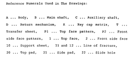
- FIG. 1 is a plan view of a transfer sheet used in the present invention
- Fig. 2 is a longitudinal sectional view of a pattern imparting machine according to the present invention, wherein (a) shows a condition before a body descends and (b) is a condition after the body has descended.
- examples of material for a plastics molded article which will become a key cap include plastics capable of being dyed with thermally migrateable dyes as will be described later, for example, polybutylene terephthalate, polyethylene terephthalate, polycarbonate, triacetate, diacetate, polyether salfone, aromatic nylon, 6,6-nylon and others, and a metal or the like having a surface coated with said plastics.
- plastics capable of being dyed with thermally migrateable dyes as will be described later, for example, polybutylene terephthalate, polyethylene terephthalate, polycarbonate, triacetate, diacetate, polyether salfone, aromatic nylon, 6,6-nylon and others, and a metal or the like having a surface coated with said plastics.
- the shape thereof it may be not only the one having a flat top face, but also the one having a concave or convex top face.
- a key cap matrix K of such a material and such a top face shape is arranged
- a transfer sheet T used in the present invention is the one wherein patterns of characters and/or symbols are formed on a support sheet 10.
- the support sheet 10 include sheet-like materials normally used in a transfer sheet, for example, non-coated papers such as medium-quality papers, high-quality papers and kraft papers, a metallic foil such as an aluminum foil, and heat-resistant plastics films such as polybutylene terephthalate film, polyethylene terephthalate film, polyvinyl chloride film and nylon film, and a laminate of these.
- the pattern of characters and/or symbols is formed by printing with the use of an ink containing the thermally migrateable dyes.
- the thermally migrateable dyes are of a type capable of being thermally diffused during a heat treatment as will be described later to dye a surface of the key cap matrix K. Examples of the thermally migrateable dyes include dispersed dyes, oil soluble dyes, basic dyes and others.
- the pattern of characters and/or symbols is formed in pair consisting of a top face pattern P1 and a front side face pattern P2. In this case, both of the top face pattern PI and the front side face pattern P2 may be constituted in multi-color.
- the transfer sheet T is provided with a line of fracture 11 around the front side face pattern P2 at least excluding an area lying between the front side face pattern P2 and the top face pattern Pl.
- This line of fracture 11 is cut by a side pad 21 during a transfer printing to enable the front side face pattern P2 to be tightly applied to a predetermined position of a front side face 2 of the key cap matrix K.
- the transfer sheet T used in the present invention is merely required to satisfy the foregoing requirements. If these requirements are satisfied, the same transfer sheet T may be formed with some other patterns or some other lines of fracture (See Fig. 1). By way of example, only the top face pattern Pl with no front side face pattern P2, or the one in which a line of fracture 12 is also provided around the top face pattern Pl, may be used. It is to be noted that if the line of fracture 12 is provided around this top face pattern Pl, it is effective in the case where a top face 1 of the key cap matrix K is of a concave shape. In other words, during the transfer printing, a top pad 20 can cut along the line of fracture 12 to facilitate the tight contact of the top face pattern Pl to the top face 1.
- Both of the lines of fracture 11 and 12 are constituted by a line of half-cut or a line of perforations.
- the line of half-cut means a line of cut formed deep in the support sheet about half the thickness thereof across the thickness of the support sheet, whereas the line of perforations means a series of holes extending completely through the thickness of the support sheet.
- the transfer sheet T is fixed under stretched condition by a transfer sheet fixing frame (not shown) with the side of the patterns of characters and/or symbols oriented downwards.
- Both of the top pad 20 and the side pad 21 used in the present invention make use of an elastic body such as a silicone rubber having a hardness of, for example, 5 to 5 0 degrees or the like.
- the top pad 20 is operable to press the transfer sheet T against the top face 1 of the key cap matrix K for the tight contact.
- the side pad 21 is operable to press the transfer sheet T against the front side face 2 of the key cap matrix K to cause the transfer sheet T to bend at the area between the top face pattern Pl and the front side face pattern P2 and also to cut along the line of fracture 11 to allow the front side face pattern P2 to be tightly applied to the front side face 2.
- each of the top pad 20 and the side pad 21 is preferably in accord with the shape of the top face 20 or the front side face 21, respectively, of the key cap matrix K.
- the top face 1 of the key cap matrix K is of a concave shape
- a heating condition is adopted by selecting a temperature and a time required for the thermally migrateable dyes to migrate by thermal diffusion to the top face 1 and the front side face 2. Accordingly, the condition therefor varies depending on the kind of the thermally migrateable dyes used and the type of material for the key cap matrix K.
- a heating method there is (1) a method wherein only the key cap matrix K is kept heated before the transfer sheet T is tightly applied to the key cap matrix K, (2) a method wherein, after the transfer sheet T has been tightly applied to the key cap matrix K, it is left in a heated atmosphere in the form as it is, (3) a method wherein, at the time the transfer sheet T is applied to the key cap matrix K, the use is made of the heated top pad 20 and the heated side pad 21, and others.
- a method according to a combination of (1) and (3) is most preferred because a sufficient heat can be efficiently imparted to the key cap matrix K and because a continuous work is possible.
- the heating condition and the dyeing mechanism in this case are as follows.
- the key cap matrix K is heated for 50 to 360 seconds by an electromagnetic wave of 1.5 to 1,000um, particularly 4 to 50um, in wavelength to about 150 to 230°C.
- the transfer sheet T is tightly applied to the top face 1 nd the front side face 2 of the key cap matrix K by the use of the top pad 20 and the side pad 21 which have been heated by a heater to 100 to 200°C.
- the thermally migrateable dyes within the patterns of the transfer sheet T are activated by the heat of the key cap matrix K, and, when this condition is maintained for a predetermined time (t to 60 seconds), the thermally migrateable dyes migrate to the top face 1 and the front side face 2 of the key cap matrix to form a desired pattern.
- the key cap having the patterns of characters and/or symbols on the top and front side faces according to the present invention can be obtained. It is needless to say that the top face pattern F1 and the front side face pattern P2 are accurately imparted to predetermined positions.
- the pattern imparting machine according to the present invention is constituted by a body A, a main shaft B, an auxiliary shaft C and a return mechanism D.
- the body A supports the main shaft B, the auxiliary shaft C and the return mechanism D. And, this body A is rendered movable up and down when incorporated in the transfer apparatus. It is to be noted that, industrially, when the body A is incorporated in the transfer apparatus, it is designed to cause a plurality of bodies A to move simultaneously.
- the main shaft B has the top pad 20 at its tip and is movable up and down within the body A.
- An upper portion of the main shaft B is arranged within a slide hole 22 provided within the body A and descends together therewith, when the body A descends, to permit the top pad 20 to abut the top face 1 of the key cap matrix K positioned therebelow, the top pad 20 being brought into tight contact with the top face 1 due to a descending force being further applied.
- the main shaft B elevates relative to the body A.
- the auxiliary shaft C has the side pad 21 at its tip and is movable in a direction towards the main shaft B from lateral direction in response to elevation of the main shaft B.
- this auxiliary shaft C is in the form as bent, and the bent is journalled within the body A. It is so constructed that, when the main shaft B descends as a result of the descent of the body A with the top pad 20 at the tip thereof brought into tight contact with the top face 1, an upper portion of the auxiliary shaft C can be kicked by the elevation of the main shaft B.
- a lower portion of the auxiliary shaft C moves towards the main shaft B from lateral direction in unison with the movement thereof to abut against the front side face 2 of the key cap matrix K, the side pad P2 being brought into tight contact with the front side face 2 due to a descending force being further applied to the body A.
- the return mechanism D is operable to act in a direction reverse to the directions of movement of the main shaft B and the auxiliary shaft C when the main shaft B elevates and the auxiliary shaft C moves towards the main shaft B.
- the pattern imparting machine according to the present invention is not limited to that described in Fig. 2, but may include numerous modes of embodiment.
- a pinion-and-rack mechanism may be employed instead of a mechanism shown in Fig. 2.
- the method of making the plastics molded articles having the patterns of characters and/or symbols on the top and front side faces according to the present invention has the following effects. That is, since the heat treatment is effected while the top and front side faces of the plastics molded articles have been tightly applied with the top face and front side face patterns of the transfer sheet, the plastics molded articles having the patterns of characters and/or symbols on the top and front side faces can be manufactured with good productivity and at inexpensive cost. Moreover, since the top and front side face patterns which have been formed on the transfer sheet are simultaneously printed on the top and front side faces of the plastics molded articles, any ;misprint in combination of characters for the top face and characters for the front side face can be completely avoided.
- the pattern imparting machine according to the present invention is of a continuous drive structure, the patterns of characters and/or symbols can be imparted to the top and front side faces of the plastics molded articles with good productivity and at inexpensive cost.
Landscapes
- Printing Methods (AREA)
- Thermal Transfer Or Thermal Recording In General (AREA)
- Decoration By Transfer Pictures (AREA)
Applications Claiming Priority (2)
| Application Number | Priority Date | Filing Date | Title |
|---|---|---|---|
| JP40696/85 | 1985-02-28 | ||
| JP60040696A JPS61200000A (ja) | 1985-02-28 | 1985-02-28 | 天面及び前側面に文字・記号等のパタ−ンを有するプラスチツクス成型品の製造方法及びパタ−ン付与機 |
Publications (2)
| Publication Number | Publication Date |
|---|---|
| EP0215954A1 true EP0215954A1 (de) | 1987-04-01 |
| EP0215954A4 EP0215954A4 (de) | 1989-02-02 |
Family
ID=12587718
Family Applications (1)
| Application Number | Title | Priority Date | Filing Date |
|---|---|---|---|
| EP19860901508 Withdrawn EP0215954A4 (de) | 1985-02-28 | 1986-02-26 | Verfahren zur herstellung von musterungen aufweisenden, geformten produkten, z.b. buchstaben und symbole auf ihrer ober- und vorderseite und musterungsvorrichtung. |
Country Status (4)
| Country | Link |
|---|---|
| US (1) | US4764177A (de) |
| EP (1) | EP0215954A4 (de) |
| JP (1) | JPS61200000A (de) |
| WO (1) | WO1986005145A1 (de) |
Families Citing this family (11)
| Publication number | Priority date | Publication date | Assignee | Title |
|---|---|---|---|---|
| JPS61200000A (ja) * | 1985-02-28 | 1986-09-04 | 日本写真印刷株式会社 | 天面及び前側面に文字・記号等のパタ−ンを有するプラスチツクス成型品の製造方法及びパタ−ン付与機 |
| JPS63182486A (ja) * | 1987-01-21 | 1988-07-27 | ポリプラスチックス株式会社 | 熱可塑性樹脂成形品に対する文字、記号、図形の付与方法 |
| CA2020276A1 (en) * | 1989-07-05 | 1991-01-06 | Terutaka Sano | Polybutylene terephthalate resin molded article having pictorial pattern formed thereon and process for preparation thereof |
| CA2021887A1 (en) * | 1989-07-26 | 1991-01-27 | Shigeru Nedzu | Polyalkylene terephthalate resin molded article having pictorial pattern formed thereon and process for preparation thereof |
| CA2022667A1 (en) * | 1989-08-09 | 1991-02-10 | Yoichi Ebina | Polybutylene terephthalate resin molded article having pictorial pattern formed thereon and process for preparing thereof |
| DE4005939A1 (de) * | 1990-02-26 | 1991-08-29 | Cassella Ag | Verwendung von farbstoffen fuer das sublimations-transferverfahren |
| US5147495A (en) * | 1990-12-03 | 1992-09-15 | Douglas James M | Thermal transfer device |
| JPH04126224U (ja) * | 1991-04-30 | 1992-11-17 | タキロン株式会社 | 調光パネル |
| US5600359A (en) * | 1993-07-14 | 1997-02-04 | Sony Corporation | Thermal transfer printing method and apparatus |
| KR101083353B1 (ko) | 2009-11-17 | 2011-11-17 | 김흥구 | 3도 자동 패드인쇄방법 및 장치 |
| CN110421989B (zh) * | 2019-08-02 | 2021-02-02 | 长兴旗开机械设备有限公司 | 一种瓶盖激光打码用瓶盖定位方法 |
Family Cites Families (6)
| Publication number | Priority date | Publication date | Assignee | Title |
|---|---|---|---|---|
| JPS58155957A (ja) * | 1982-03-10 | 1983-09-16 | Nissha Printing Co Ltd | 文字、記号付キ−キヤツプの製造方法 |
| JPS5941292A (ja) * | 1982-09-01 | 1984-03-07 | Nissha Printing Co Ltd | 文字、模様付成型品の製造方法 |
| JPS5960825A (ja) * | 1982-09-29 | 1984-04-06 | ブラザー工業株式会社 | キ−釦 |
| JPS59182781A (ja) * | 1983-03-31 | 1984-10-17 | Toppan Printing Co Ltd | プラスチツク成形品への絵付け方法 |
| US4662966A (en) * | 1984-09-26 | 1987-05-05 | Nissha Printing Co. Ltd. | Apparatus for transfer printing |
| JPS61200000A (ja) * | 1985-02-28 | 1986-09-04 | 日本写真印刷株式会社 | 天面及び前側面に文字・記号等のパタ−ンを有するプラスチツクス成型品の製造方法及びパタ−ン付与機 |
-
1985
- 1985-02-28 JP JP60040696A patent/JPS61200000A/ja active Granted
-
1986
- 1986-02-26 WO PCT/JP1986/000092 patent/WO1986005145A1/ja not_active Ceased
- 1986-02-26 US US06/931,724 patent/US4764177A/en not_active Expired - Lifetime
- 1986-02-26 EP EP19860901508 patent/EP0215954A4/de not_active Withdrawn
Non-Patent Citations (2)
| Title |
|---|
| No relevant documents have been disclosed. * |
| See also references of WO8605145A1 * |
Also Published As
| Publication number | Publication date |
|---|---|
| JPS61200000A (ja) | 1986-09-04 |
| EP0215954A4 (de) | 1989-02-02 |
| JPH0244719B2 (de) | 1990-10-04 |
| WO1986005145A1 (fr) | 1986-09-12 |
| US4764177A (en) | 1988-08-16 |
Similar Documents
| Publication | Publication Date | Title |
|---|---|---|
| US4764177A (en) | Method of transfer printing plastic molded articles having patterns of characters and/or symbols on their top faces and front side faces and pattern imparting machine | |
| US5603259A (en) | In-line cold foil transfer process and apparatus | |
| JPH01225553A (ja) | プラスチック成形体浸透印刷装置 | |
| US3826167A (en) | Sign forming apparatus, method and die for use therein | |
| JPH0413154B2 (de) | ||
| GB2329606A (en) | Method of producing film with through-holes | |
| KR880701185A (ko) | 인쇄개선책 | |
| JPH0454593B2 (de) | ||
| CN211843636U (zh) | 一种烫金装置及移印烫金设备 | |
| JPH032667B2 (de) | ||
| JPH033410Y2 (de) | ||
| JPH0210441B2 (de) | ||
| JPS6343119Y2 (de) | ||
| KR20020045675A (ko) | 핫 스탬핑호일을 이용한 표면인쇄방법 | |
| JPH0586906B2 (de) | ||
| ATE65746T1 (de) | Vorrichtung zum entwerfen. | |
| JPS5916778A (ja) | 文字、記号付合成樹脂成型品の製造方法 | |
| JPH0225678Y2 (de) | ||
| JPH0111518Y2 (de) | ||
| CN219446475U (zh) | 一种防伪标签生产用自动化设备 | |
| JPH0755065Y2 (ja) | ホットスタンピング転写用版 | |
| KR200274118Y1 (ko) | 직물에 2가지 색상의 포일을 인쇄하는 장치 | |
| JPH0343009Y2 (de) | ||
| JPS59215867A (ja) | キ−キヤツプの取り出し方法 | |
| JPS6328671A (ja) | ラベルプリント装置 |
Legal Events
| Date | Code | Title | Description |
|---|---|---|---|
| PUAI | Public reference made under article 153(3) epc to a published international application that has entered the european phase |
Free format text: ORIGINAL CODE: 0009012 |
|
| 17P | Request for examination filed |
Effective date: 19861031 |
|
| AK | Designated contracting states |
Kind code of ref document: A1 Designated state(s): DE FR GB IT NL |
|
| A4 | Supplementary search report drawn up and despatched |
Effective date: 19890202 |
|
| 17Q | First examination report despatched |
Effective date: 19901114 |
|
| STAA | Information on the status of an ep patent application or granted ep patent |
Free format text: STATUS: THE APPLICATION IS DEEMED TO BE WITHDRAWN |
|
| 18D | Application deemed to be withdrawn |
Effective date: 19910326 |
|
| RIN1 | Information on inventor provided before grant (corrected) |
Inventor name: INAKO, YOSHIHIDE406, SHATORESHIN, 30-6 Inventor name: SUMI, TAKAO28, NISHISHICHIJO NAKANO-CHO Inventor name: NISHIDA, MASAHIRO2-2, NAKAMURA-CHO |