EP0215962A1 - Embrayage ou frein, engagé ou dégagé électromagnétiquement - Google Patents
Embrayage ou frein, engagé ou dégagé électromagnétiquement Download PDFInfo
- Publication number
- EP0215962A1 EP0215962A1 EP85111321A EP85111321A EP0215962A1 EP 0215962 A1 EP0215962 A1 EP 0215962A1 EP 85111321 A EP85111321 A EP 85111321A EP 85111321 A EP85111321 A EP 85111321A EP 0215962 A1 EP0215962 A1 EP 0215962A1
- Authority
- EP
- European Patent Office
- Prior art keywords
- pole
- rings
- brake
- ring
- magnet housing
- Prior art date
- Legal status (The legal status is an assumption and is not a legal conclusion. Google has not performed a legal analysis and makes no representation as to the accuracy of the status listed.)
- Withdrawn
Links
Images

Classifications
-
- F—MECHANICAL ENGINEERING; LIGHTING; HEATING; WEAPONS; BLASTING
- F16—ENGINEERING ELEMENTS AND UNITS; GENERAL MEASURES FOR PRODUCING AND MAINTAINING EFFECTIVE FUNCTIONING OF MACHINES OR INSTALLATIONS; THERMAL INSULATION IN GENERAL
- F16D—COUPLINGS FOR TRANSMITTING ROTATION; CLUTCHES; BRAKES
- F16D55/00—Brakes with substantially-radial braking surfaces pressed together in axial direction, e.g. disc brakes
- F16D55/02—Brakes with substantially-radial braking surfaces pressed together in axial direction, e.g. disc brakes with axially-movable discs or pads pressed against axially-located rotating members
-
- F—MECHANICAL ENGINEERING; LIGHTING; HEATING; WEAPONS; BLASTING
- F16—ENGINEERING ELEMENTS AND UNITS; GENERAL MEASURES FOR PRODUCING AND MAINTAINING EFFECTIVE FUNCTIONING OF MACHINES OR INSTALLATIONS; THERMAL INSULATION IN GENERAL
- F16D—COUPLINGS FOR TRANSMITTING ROTATION; CLUTCHES; BRAKES
- F16D27/00—Magnetically- or electrically- actuated clutches; Control or electric circuits therefor
- F16D27/02—Magnetically- or electrically- actuated clutches; Control or electric circuits therefor with electromagnets incorporated in the clutch, i.e. with collecting rings
- F16D27/04—Magnetically- or electrically- actuated clutches; Control or electric circuits therefor with electromagnets incorporated in the clutch, i.e. with collecting rings with axially-movable friction surfaces
- F16D27/06—Magnetically- or electrically- actuated clutches; Control or electric circuits therefor with electromagnets incorporated in the clutch, i.e. with collecting rings with axially-movable friction surfaces with friction surfaces arranged within the flux
-
- F—MECHANICAL ENGINEERING; LIGHTING; HEATING; WEAPONS; BLASTING
- F16—ENGINEERING ELEMENTS AND UNITS; GENERAL MEASURES FOR PRODUCING AND MAINTAINING EFFECTIVE FUNCTIONING OF MACHINES OR INSTALLATIONS; THERMAL INSULATION IN GENERAL
- F16D—COUPLINGS FOR TRANSMITTING ROTATION; CLUTCHES; BRAKES
- F16D27/00—Magnetically- or electrically- actuated clutches; Control or electric circuits therefor
- F16D27/10—Magnetically- or electrically- actuated clutches; Control or electric circuits therefor with an electromagnet not rotating with a clutching member, i.e. without collecting rings
- F16D27/108—Magnetically- or electrically- actuated clutches; Control or electric circuits therefor with an electromagnet not rotating with a clutching member, i.e. without collecting rings with axially movable clutching members
- F16D27/112—Magnetically- or electrically- actuated clutches; Control or electric circuits therefor with an electromagnet not rotating with a clutching member, i.e. without collecting rings with axially movable clutching members with flat friction surfaces, e.g. discs
-
- F—MECHANICAL ENGINEERING; LIGHTING; HEATING; WEAPONS; BLASTING
- F16—ENGINEERING ELEMENTS AND UNITS; GENERAL MEASURES FOR PRODUCING AND MAINTAINING EFFECTIVE FUNCTIONING OF MACHINES OR INSTALLATIONS; THERMAL INSULATION IN GENERAL
- F16D—COUPLINGS FOR TRANSMITTING ROTATION; CLUTCHES; BRAKES
- F16D59/00—Self-acting brakes, e.g. coming into operation at a predetermined speed
- F16D59/02—Self-acting brakes, e.g. coming into operation at a predetermined speed spring-loaded and adapted to be released by mechanical, fluid, or electromagnetic means
-
- F—MECHANICAL ENGINEERING; LIGHTING; HEATING; WEAPONS; BLASTING
- F16—ENGINEERING ELEMENTS AND UNITS; GENERAL MEASURES FOR PRODUCING AND MAINTAINING EFFECTIVE FUNCTIONING OF MACHINES OR INSTALLATIONS; THERMAL INSULATION IN GENERAL
- F16D—COUPLINGS FOR TRANSMITTING ROTATION; CLUTCHES; BRAKES
- F16D27/00—Magnetically- or electrically- actuated clutches; Control or electric circuits therefor
- F16D2027/008—Details relating to the magnetic circuit, or to the shape of the clutch parts to achieve a certain magnetic path
-
- F—MECHANICAL ENGINEERING; LIGHTING; HEATING; WEAPONS; BLASTING
- F16—ENGINEERING ELEMENTS AND UNITS; GENERAL MEASURES FOR PRODUCING AND MAINTAINING EFFECTIVE FUNCTIONING OF MACHINES OR INSTALLATIONS; THERMAL INSULATION IN GENERAL
- F16D—COUPLINGS FOR TRANSMITTING ROTATION; CLUTCHES; BRAKES
- F16D2121/00—Type of actuator operation force
- F16D2121/18—Electric or magnetic
- F16D2121/20—Electric or magnetic using electromagnets
- F16D2121/22—Electric or magnetic using electromagnets for releasing a normally applied brake
Definitions
- the present invention relates to a work or quiescent current operated electromagnetic clutch or brake with a magnet housing and, in the case of a clutch, a rotor with at least one pole ring.
- Electromagnetic clutches or brakes of the generic type are known per se.
- An additional pole ring is used in such clutches or brakes in order to achieve multiple magnetic flooding of an armature disk and thus an increase in the clutch or braking effect.
- the pole ring is embedded in a compound which, on the other hand, connects an outer and an inner ring made of magnetic material to one another. This entire assembly is then connected to a magnet housing or a rotor so that it cannot rotate, the rings held together by the composite material forming the outer and the inner pole face of the magnet housing or the rotor.
- the present invention has for its object to design an electromagnetic clutch or brake of the generic type so that the disadvantages described above are avoided, i. that is, the attachment of at least one pole ring to the magnet housing or to the rotor is simplified in terms of production technology and that gap losses are avoided in functional terms.
- pole ring or the pole rings is or are attached to a ring-like support disk made of an antimagnetic material and that is made of support disc and pole ring or pole rings existing unit is fixed against rotation in an annular recess of the magnet housing or the rotor.
- the functional advantage is achieved that gap losses during magnetic flux cannot occur.
- the outer and inner ring surfaces of the magnet housing or of the rotor form the outer and inner pole surfaces, as is also the case with electromagnetic clutches or brakes without multiple flooding. At least one additional pole ring is provided only for the multiple flooding, which is connected to the support disk as a structural unit with the magnet housing or the rotor so as to be secured against rotation.
- friction lining rings can be connected in a rotationally secure manner to the support disk.
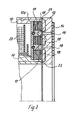
- reference number 10 denotes a magnet housing of an electromagnet coupling that can be mounted in a stationary manner.
- a rotor 11 which can be fixed axially and non-rotatably on a drive shaft, not shown, lies axially opposite an armature disk 12.
- the armature disk 12 is connected to a belt pulley 13 so that it cannot rotate, but is axially displaceable.
- a spring washer 14 is provided as the connecting means, which enables the axial movement of the armature disk 12 with respect to the axially and displaceably fixable pulley 13.
- the rotor 11 in the region of an annular recess 15 is equipped with a structural unit which consists of a support disk 16 made of an antimagnetic material, a pole ring 17 connected to it so that it cannot rotate, and is arranged concentrically with this and also secured against rotation with the support disk 15 connected friction lining rings 18.
- This assembly listed above is fixed against rotation and fixed in the recess 15 of the rotor 11.
- the armature disk 12 is provided in the area opposite the pole ring 17 with an air gap formed by a slot 19.
- Figure 3 makes it clear that a plurality of pole rings 17 can be easily attached to a support plate 16, so that there is an even more frequent flooding of the armature disc 12 of an electromagnetic clutch or brake results.
- the magnetic flux is made clear by the particularly highlighted and arrowed line. It is clear that in the exemplary embodiment according to FIG. 3, the armature disk 12 is flooded three times as soon as the coil 20 of the magnet housing 10 is excited.
- the pole rings 17 can be connected to the support disk 16, for example by screws 23, but there is also the possibility of riveting the pole rings 17 to the support disk 16.
- the friction lining rings 18 are expediently glued to the support disk 16.
Landscapes
- Engineering & Computer Science (AREA)
- General Engineering & Computer Science (AREA)
- Mechanical Engineering (AREA)
- Physics & Mathematics (AREA)
- Electromagnetism (AREA)
- Braking Arrangements (AREA)
Priority Applications (1)
| Application Number | Priority Date | Filing Date | Title |
|---|---|---|---|
| EP85111321A EP0215962A1 (fr) | 1985-09-07 | 1985-09-07 | Embrayage ou frein, engagé ou dégagé électromagnétiquement |
Applications Claiming Priority (1)
| Application Number | Priority Date | Filing Date | Title |
|---|---|---|---|
| EP85111321A EP0215962A1 (fr) | 1985-09-07 | 1985-09-07 | Embrayage ou frein, engagé ou dégagé électromagnétiquement |
Publications (1)
| Publication Number | Publication Date |
|---|---|
| EP0215962A1 true EP0215962A1 (fr) | 1987-04-01 |
Family
ID=8193749
Family Applications (1)
| Application Number | Title | Priority Date | Filing Date |
|---|---|---|---|
| EP85111321A Withdrawn EP0215962A1 (fr) | 1985-09-07 | 1985-09-07 | Embrayage ou frein, engagé ou dégagé électromagnétiquement |
Country Status (1)
| Country | Link |
|---|---|
| EP (1) | EP0215962A1 (fr) |
Cited By (11)
| Publication number | Priority date | Publication date | Assignee | Title |
|---|---|---|---|---|
| AU601209B2 (en) * | 1986-09-05 | 1990-09-06 | Sanden Corporation | Electromagnetic clutch having high torque transfer |
| US5305865A (en) * | 1993-03-05 | 1994-04-26 | Dana Corporation | Rotor for electromagnetic coupling |
| EP0645550A3 (fr) * | 1993-08-30 | 1995-06-28 | Dana Corp | Disque d'accouplement électromagnétique. |
| WO2000014420A1 (fr) * | 1998-09-02 | 2000-03-16 | Continental Isad Electronic Systems Gmbh & Co. Ohg | Systeme de freinage pour arbre accouple a une roue d'automobile |
| DE19747114B4 (de) * | 1996-10-25 | 2005-05-25 | Warner Françe | Elektromagnetisch betätigte Scheibenbremse für Hublader |
| DE102010055647A1 (de) * | 2010-12-22 | 2012-06-28 | Volkswagen Aktiengesellschaft | Magnetkupplungsvorrichtung mit einer Reibvorrichtung sowie Reibvorrichtung für eine solche Magnetkupplungsvorrichtung |
| DE102004015655B4 (de) * | 2003-04-07 | 2017-03-02 | Schaeffler Technologies AG & Co. KG | Elektromagnetische Reibkupplung |
| CN108087094A (zh) * | 2017-12-26 | 2018-05-29 | 昆山隆中麦士格瑞汽车部件有限公司 | 具有双摩擦盘的电磁离合器水泵 |
| CN113195917A (zh) * | 2018-12-04 | 2021-07-30 | 敏思工业公司 | 用于控制非摩擦式耦合组件的操作模式的电磁系统以及具有该电磁系统的耦合和磁性控制组件 |
| DE102020103661A1 (de) | 2020-02-12 | 2021-08-12 | Wittenstein Se | Haltebremse für einen Antrieb |
| CN119062695A (zh) * | 2024-08-15 | 2024-12-03 | 深圳市大族机器人有限公司 | 制动器 |
Citations (6)
| Publication number | Priority date | Publication date | Assignee | Title |
|---|---|---|---|---|
| DE833747C (de) * | 1949-07-18 | 1952-03-13 | Citroen Sa Andre | Elektromagnetisch betaetigte Reibungskupplung oder -bremse |
| GB726487A (en) * | 1953-07-07 | 1955-03-16 | Warner Electric Brake & Clutch | Improvements in electromagnetic clutches |
| US2860403A (en) * | 1953-06-30 | 1958-11-18 | Warner Electric Brake & Clutch | Method of making a pole piece unit for magnets |
| US3465862A (en) * | 1968-04-15 | 1969-09-09 | Bendix Corp | Stationary coil electromagnetic clutch or brake |
| GB2017232A (en) * | 1978-03-27 | 1979-10-03 | Hitachi Ltd | Electromagnetic clutch and method of manufacture |
| US4471860A (en) * | 1981-04-27 | 1984-09-18 | Matsushita Electric Industrial Co., Ltd. | Electromagnetic clutch |
-
1985
- 1985-09-07 EP EP85111321A patent/EP0215962A1/fr not_active Withdrawn
Patent Citations (6)
| Publication number | Priority date | Publication date | Assignee | Title |
|---|---|---|---|---|
| DE833747C (de) * | 1949-07-18 | 1952-03-13 | Citroen Sa Andre | Elektromagnetisch betaetigte Reibungskupplung oder -bremse |
| US2860403A (en) * | 1953-06-30 | 1958-11-18 | Warner Electric Brake & Clutch | Method of making a pole piece unit for magnets |
| GB726487A (en) * | 1953-07-07 | 1955-03-16 | Warner Electric Brake & Clutch | Improvements in electromagnetic clutches |
| US3465862A (en) * | 1968-04-15 | 1969-09-09 | Bendix Corp | Stationary coil electromagnetic clutch or brake |
| GB2017232A (en) * | 1978-03-27 | 1979-10-03 | Hitachi Ltd | Electromagnetic clutch and method of manufacture |
| US4471860A (en) * | 1981-04-27 | 1984-09-18 | Matsushita Electric Industrial Co., Ltd. | Electromagnetic clutch |
Cited By (12)
| Publication number | Priority date | Publication date | Assignee | Title |
|---|---|---|---|---|
| AU601209B2 (en) * | 1986-09-05 | 1990-09-06 | Sanden Corporation | Electromagnetic clutch having high torque transfer |
| US5305865A (en) * | 1993-03-05 | 1994-04-26 | Dana Corporation | Rotor for electromagnetic coupling |
| EP0645550A3 (fr) * | 1993-08-30 | 1995-06-28 | Dana Corp | Disque d'accouplement électromagnétique. |
| US5445259A (en) * | 1993-08-30 | 1995-08-29 | Dana Corporation | High strength electromagnetic coupling disc |
| DE19747114B4 (de) * | 1996-10-25 | 2005-05-25 | Warner Françe | Elektromagnetisch betätigte Scheibenbremse für Hublader |
| WO2000014420A1 (fr) * | 1998-09-02 | 2000-03-16 | Continental Isad Electronic Systems Gmbh & Co. Ohg | Systeme de freinage pour arbre accouple a une roue d'automobile |
| DE102004015655B4 (de) * | 2003-04-07 | 2017-03-02 | Schaeffler Technologies AG & Co. KG | Elektromagnetische Reibkupplung |
| DE102010055647A1 (de) * | 2010-12-22 | 2012-06-28 | Volkswagen Aktiengesellschaft | Magnetkupplungsvorrichtung mit einer Reibvorrichtung sowie Reibvorrichtung für eine solche Magnetkupplungsvorrichtung |
| CN108087094A (zh) * | 2017-12-26 | 2018-05-29 | 昆山隆中麦士格瑞汽车部件有限公司 | 具有双摩擦盘的电磁离合器水泵 |
| CN113195917A (zh) * | 2018-12-04 | 2021-07-30 | 敏思工业公司 | 用于控制非摩擦式耦合组件的操作模式的电磁系统以及具有该电磁系统的耦合和磁性控制组件 |
| DE102020103661A1 (de) | 2020-02-12 | 2021-08-12 | Wittenstein Se | Haltebremse für einen Antrieb |
| CN119062695A (zh) * | 2024-08-15 | 2024-12-03 | 深圳市大族机器人有限公司 | 制动器 |
Similar Documents
| Publication | Publication Date | Title |
|---|---|---|
| CH618243A5 (en) | Magnetically actuated friction clutch or brake | |
| DE2416238C2 (de) | Kupplungsmotor | |
| EP0215962A1 (fr) | Embrayage ou frein, engagé ou dégagé électromagnétiquement | |
| DE102008016277A1 (de) | Elektromagnetisch betätigbare Kupplung sowie Wasserpumpe mit einer elektromagnetisch betätigbaren Kupplung | |
| DE19737485C1 (de) | Elektromagnetisch betätigbare Bremse und Mehrfachbremsaggregat | |
| DE2627161A1 (de) | Selbsteinstellende elektromagnetkupplung | |
| EP0222312B1 (fr) | Frein à ressort accumulé | |
| DE2135821A1 (de) | Reibungsvorrichtung | |
| DE2215753A1 (de) | Elektromagnetische Kupplung | |
| EP0111350B1 (fr) | Moteur électrique équipé d'un frein d'arrêt | |
| DE2755887A1 (de) | Abgedichtete elektromagnetische kupplung fuer textilmaschinen | |
| DE102010045447A1 (de) | Elektromotor | |
| DE19857950A1 (de) | Elektromotor mit einer integrierten, drehspielfreien, elektromagnetisch betätigten Bremse | |
| EP2901037B1 (fr) | Système de frein et moteur électrique équipé d'un système de frein | |
| DE1114573B (de) | Mit einem Elektromotor zusammengebaute Bremsvorrichtung | |
| EP4246008A1 (fr) | Frein ou embrayage électromagnétique | |
| EP0341653B1 (fr) | Dispositif de transmission avec embrayage double commandé électromagnétiquement | |
| EP4184032B1 (fr) | Frein à ressort à commande électromagnétique | |
| DE102010050346B4 (de) | Elektromagnetisch betätigbare Bremse und Verfahren zum Betreiben einer Bremse | |
| DE102006007688A1 (de) | Elektromagnetisch betätigbare Schalteinheit | |
| DE2841207A1 (de) | Elektromagnetisch gelueftete, federbetaetigte teilscheibenbremse | |
| EP0505703A1 (fr) | Moteur électrique équipé d'un frein à action automatique | |
| CH694134A5 (de) | Elektromagnetisch betätigte Einflächenkupplung oder Einflächenbremse. | |
| DE102015213740A1 (de) | Elektromagnetische Konusbremse und Personenbeförderungsmittelantrieb | |
| EP3760892A1 (fr) | Frein à disques multiples pour dispositif d'entraînement de véhicule |
Legal Events
| Date | Code | Title | Description |
|---|---|---|---|
| PUAI | Public reference made under article 153(3) epc to a published international application that has entered the european phase |
Free format text: ORIGINAL CODE: 0009012 |
|
| AK | Designated contracting states |
Kind code of ref document: A1 Designated state(s): CH DE FR GB IT LI |
|
| 17P | Request for examination filed |
Effective date: 19870925 |
|
| 17Q | First examination report despatched |
Effective date: 19880915 |
|
| STAA | Information on the status of an ep patent application or granted ep patent |
Free format text: STATUS: THE APPLICATION IS DEEMED TO BE WITHDRAWN |
|
| 18D | Application deemed to be withdrawn |
Effective date: 19890127 |
|
| RIN1 | Information on inventor provided before grant (corrected) |
Inventor name: BRINKMANN, KARL-ERNST |