EP2901037B1 - Système de frein et moteur électrique équipé d'un système de frein - Google Patents
Système de frein et moteur électrique équipé d'un système de frein Download PDFInfo
- Publication number
- EP2901037B1 EP2901037B1 EP13750849.5A EP13750849A EP2901037B1 EP 2901037 B1 EP2901037 B1 EP 2901037B1 EP 13750849 A EP13750849 A EP 13750849A EP 2901037 B1 EP2901037 B1 EP 2901037B1
- Authority
- EP
- European Patent Office
- Prior art keywords
- brake
- arrangement according
- limiting means
- braking arrangement
- axially
- Prior art date
- Legal status (The legal status is an assumption and is not a legal conclusion. Google has not performed a legal analysis and makes no representation as to the accuracy of the status listed.)
- Active
Links
Images

Classifications
-
- F—MECHANICAL ENGINEERING; LIGHTING; HEATING; WEAPONS; BLASTING
- F16—ENGINEERING ELEMENTS AND UNITS; GENERAL MEASURES FOR PRODUCING AND MAINTAINING EFFECTIVE FUNCTIONING OF MACHINES OR INSTALLATIONS; THERMAL INSULATION IN GENERAL
- F16D—COUPLINGS FOR TRANSMITTING ROTATION; CLUTCHES; BRAKES
- F16D55/00—Brakes with substantially-radial braking surfaces pressed together in axial direction, e.g. disc brakes
- F16D55/24—Brakes with substantially-radial braking surfaces pressed together in axial direction, e.g. disc brakes with a plurality of axially-movable discs, lamellae, or pads, pressed from one side towards an axially-located member
- F16D55/26—Brakes with substantially-radial braking surfaces pressed together in axial direction, e.g. disc brakes with a plurality of axially-movable discs, lamellae, or pads, pressed from one side towards an axially-located member without self-tightening action
- F16D55/36—Brakes with a plurality of rotating discs all lying side by side
-
- F—MECHANICAL ENGINEERING; LIGHTING; HEATING; WEAPONS; BLASTING
- F16—ENGINEERING ELEMENTS AND UNITS; GENERAL MEASURES FOR PRODUCING AND MAINTAINING EFFECTIVE FUNCTIONING OF MACHINES OR INSTALLATIONS; THERMAL INSULATION IN GENERAL
- F16D—COUPLINGS FOR TRANSMITTING ROTATION; CLUTCHES; BRAKES
- F16D2121/00—Type of actuator operation force
- F16D2121/18—Electric or magnetic
- F16D2121/20—Electric or magnetic using electromagnets
- F16D2121/22—Electric or magnetic using electromagnets for releasing a normally applied brake
Definitions
- the invention relates to a brake assembly and electric motor with a brake assembly.
- the invention is therefore the object of developing a brake assembly for an electric motor, the reliability should be improved.
- the object is achieved in the brake assembly according to the claim 1 and in the electric motor with a brake assembly according to the features indicated in claim 10.
- the brake assembly is designed with a shaft to be braked, which is mounted by means of a bearing in a housing part, in particular bearing flange and / or brake bearing plate, wherein the housing part is non-rotatably connected to a coil winding, in particular brake coil, wherein an armature disc is non-rotatably but axially movably connected to the housing part, wherein a first and a second brake pad carrier is rotatably but axially movably connected to the shaft, wherein axially between the brake pad carriers a lamella is arranged in a rotationally fixed but axially movable manner, wherein the blade is axially limited by means of a limiting means, wherein the limiting means is connected to the housing part (12), in particular non-positively, positively, cohesively, and / or firmly connected and / or is screw-connected, wherein the housing part (12) has a braking surface or is connected to a braking surface having a part, in particular non-
- the blade of such a double brake according to the invention is now defined in its axial freedom of movement. Because the axial limiting means limits the axial freedom of movement. In this case, this freedom of movement is preferably adjustable, and thus manufacturing tolerances can be compensated. Advantageously, a defined retraction of both brake pad carrier is thus achievable.
- the air gap, the two friction partners of the brake pad carrier, ie blade and armature disc, when releasing the brake or when the brake must overcome overcome, adjustable when the stopper formed on the limiting means is axially adjustable, that is displaceable.
- the limiting means is screw-connected to the spool core, so magnetic body.
- the limiting means is secured against rotation.
- a spring element for moving the blade, in particular for resetting the lamella when the coil winding is not energized and / or for pressing the lamella against the limiting means, in particular against an abutment portion, in particular shoulder, of the limiting means.
- the adjustment of the axial position of the stop of the limiting means can be done either in the ventilated or in the sunken state of the brake assembly, ie in energized or de-energized operation of the brake assembly.
- the blade made of steel, in particular made of sheet steel.
- the advantage here is that a cost-effective production is possible and that the magnetic field is exposed to a smaller air gap for the field lines of the solenoid formed by the coil winding.
- the lamella is designed as a perforated disc.
- the advantage here is that a simple production by punching or drilling is executable.
- the armature disk is made of a ferromagnetic material, in particular steel, so that when energized coil winding the armature disk is tightened axially to the magnet body out.
- the advantage here is that the magnetic resistance for the field lines of the electromagnet is low.
- the coil winding is designed as a ring winding and is accommodated in an effective as a coil core magnetic body, in particular wherein the spool core is made of cast GGG, in particular gray cast iron.
- the advantage here is that a simple production is possible. Besides, one is annular recess allows already in the casting in a material-saving manner. In the recess only the coil winding comprehensive coil carrier must be inserted.
- the limiting means comprises a stopper portion, wherein the stopper portion is radially extended further than the portion of the limiting means connecting the stopper portion to the spool core, in particular wherein the stopper portion is or is a nut threaded onto a threaded portion Screw head of a screw part.
- the limiting means for the lamella comprises a screw, in particular stud or screw, in particular wherein the screw member is connected to a part, in particular with a screw head cohesively or with a nut is screw-connected.
- the advantage here is that the axial position of the stopper is adjustable.
- each brake pad carrier axially on both sides of a respective brake pad.
- the advantage here is that a double brake can be realized, wherein the brake pad carrier can be braked by means of one of their brake pads against an axially intermediate slat.
- the lamella has a recess through which the limiting means protrudes.
- the housing part has a braking surface against which a brake pad of the first or second brake pad carrier can be pressed.
- the housing part is made of steel or cast steel.
- the advantage here is that a cost-effective production is possible.
- the shaft is a rotor shaft of the motor or is rotatably connected to the rotor shaft of the motor, wherein the rotor shaft is connected to a rotor core, on which a short-circuit cage and / or permanent magnets are arranged.
- the advantage here is that a double brake on the engine can be integrated.
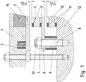
- a brake coil 14 is designed as a ring winding and in a recess of a magnetic body 1, so coil core, added.
- the recess is also annular. In this way, an electromagnet is formed, which makes a magnetic flux generated in Ringachsraum.
- the brake assembly also has a shaft to be braked, which is rotatably mounted, in particular in a brake bearing plate, which is preferably designed as a housing part 12 and thus part of the overall housing, so is housing forming.
- the shaft has a toothing or is rotatably connected to a part having a toothing, in particular sleeve part.
- a preferably disc-shaped brake pad carrier 4 has an internal toothing, which is in engagement with the toothing. In this way, the brake pad carrier 4 is arranged axially displaceable on the shaft.
- the brake pad carrier 4 has axially on both sides a brake pad 5.
- a non-rotatably connected to the magnetic body 1 armature disc 3 is energized in energized toroidal coil, so brake coil 14 to the magnetic body 1, ie axially away from the first brake pad carrier 4.
- the armature disk 3 has a centrally arranged recess through which the shaft protrudes.
- the magnetic body 1 is preferably made of a ferromagnetic material, such as cast GGG or nodular cast iron.
- the armature disk 3 is preferably made of steel.
- first spring elements 2 are based, which press on the armature disk 3.
- the armature plate 3 in de-energized toroidal coil, so brake coil 14, pushed away from the magnetic body 1, in particular fixed to the bearing plate, and thus presses on a first brake pad 5, which is provided on the axial side facing the first brake pad carrier 4.
- the first brake pad carrier 4 is pressed with its braking surface facing brake pad 5 on a rotatably connected to the magnetic body 1, but axially movable blade 6, which thus presses on a second brake pad 11, which on the side facing the blade 6 of a second rotatably connected to the shaft brake pad carrier 10 is arranged.
- the second brake pad carrier 10 in turn has an internal toothing, which is in engagement with the toothing of the shaft or with the toothing of the non-rotatably connected to the shaft part, so that the second brake pad carrier 10 is also positively connected in the circumferential direction and therefore rotatably connected to the shaft, but is slidably disposed in the axial direction.
- the armature disk 3 is guided in its axial movement of guide elements which are firmly connected to the magnetic body 1, in particular screw-connected, are. For this purpose, it has axially continuous recesses through which the guide elements protrude.
- the magnetic body 1 is screw-connected to the housing part 12, so brake bearing plate, wherein spacer sleeves, spring elements and / or screw elements for axial spacing, in particular limitation, are provided, which are effective as guide elements.
- the blade 6 can be executed as an axially thin-walled steel disc.
- a screw 8, in particular stud at least partially screwed into a threaded bore of the magnetic body 1, so screw connected to the magnetic body 1.
- a bolt-connected with the screw nut 8 7, which is screwed against a securing element 13 limits the blade 6 axially.
- the screw 8 is passed through a recess of the blade 6, in particular an axially continuous hole, in particular borehole.
- a plurality of second spring elements 9 are arranged, which are preferably spaced apart from each other in the circumferential direction and are arranged at the same radial distance.
- a respective second spring element 9 is supported on the housing part 12, so brake bearing plate, and presses against the blade 6. Thus, a defined release of the brake can be ensured.
- first spring elements 2 are arranged, which are preferably spaced from each other in the circumferential direction and regularly spaced at the same radial distance.
- a plurality of screws 8 are arranged in the circumferential direction with correspondingly axially delimiting acting nuts 7, which are preferably spaced from each other in the circumferential direction regularly and are arranged at the same radial distance.
- the second brake pad 11 and the second brake pad carrier 10 in the released state of the brake that is energized brake coil 14, a distance L / 2 from the lamella 6 and that the first brake pad 5 and the first brake pad carrier 4 has a distance L / 2 from the armature disk 3.
- the spacing of the brake pads of each braking-activating part, ie armature disk 3 and 6 lamella the same.
- the armature plate 3 presses on the first brake pad 5 of the first brake pad carrier 4, which in turn presses with its axially remote further brake pad 5 on the blade 6.
- the blade 6 is axially displaced and on the second brake pad 11 of the second Brake pad carrier 10 pressed, in turn, with its axially remote from the blade 6 further second brake pad 11 presses on the braking surface having part 12.
- the distance of the armature disk 3 from the magnetic body 1 has the value L, so the entire air gap L between the armature disk 3 and the magnetic body 1 is arranged.
- the specific air gap L / 2 between the disk 6 and the second brake pad carrier 10 with brake pad 11 by means of the nut 7 is adjustable.
- the remaining air gap is thus between the armature disk 3 and the first brake pad 5 a.
- the blade 6 instead of the stud as a screw 8 and a screw with screw head used, in which case the screw head, the blade 6 limited axial.
- the blade 6 is guided in the axial direction of a guide element.
Landscapes
- Engineering & Computer Science (AREA)
- General Engineering & Computer Science (AREA)
- Mechanical Engineering (AREA)
- Braking Arrangements (AREA)
Claims (10)
- Ensemble de frein, avec un arbre à freiner qui est monté dans un élément de boîtier au moyen d'un palier, en particulier d'une bride de palier,
sachant que l'élément de boîtier (12) est relié en solidarité de rotation à un bobinage, en particulier une bobine de frein (14),
sachant qu'un disque d'induit est relié à l'élément de boîtier (12) en solidarité de rotation mais à mobilité axiale,
sachant qu'un premier et un deuxième support de garniture de frein sont respectivement reliés à l'arbre en solidarité de rotation mais à mobilité axiale,
sachant qu'une lamelle solidaire en rotation mais axialement mobile est disposée axialement entre les supports de garniture de frein,
sachant que la lamelle est limitée axialement par un moyen de limitation,
et sachant que le moyen de limitation est relié à l'élément de boîtier (12),
caractérisé en ce que l'élément de boîtier (12) présente une surface de freinage, contre laquelle peut être pressée une garniture de frein du premier ou du deuxième support de garniture de frein,
sachant que le moyen de limitation présente une partie de butée, sachant que la partie de butée est davantage étendue radialement que la partie du moyen de limitation qui relie la partie de butée au noyau de bobine,
sachant que la partie de butée est un écrou (7) vissé sur un élément de vissage (8), ou une tête de vis d'un élément de vissage. - Ensemble de frein selon la revendication 1, caractérisé en ce qu'un élément formant ressort (9) est disposé entre la lamelle (6) et un élément relié à l'élément de boîtier, en particulier un noyau de bobine du bobinage et/ou un corps magnétique recevant le bobinage,
afin de rappeler la lamelle lorsque le bobinage n'est pas alimenté en courant, et/ou afin de presser la lamelle contre le moyen de limitation, en particulier contre une partie de butée, en particulier un gradin, du moyen de limitation. - Ensemble de frein selon au moins une des revendications précédentes, caractérisé en ce que la lamelle est fabriquée en acier, en particulier en tôle d'acier,
et/ou en ce que la lamelle est réalisée sous forme de disque perforé. - Ensemble de frein selon au moins une des revendications précédentes, caractérisé en ce que le disque d'induit est réalisé en un matériau ferromagnétique, en particulier en acier
de sorte que le disque d'induit est attiré axialement en direction du corps magnétique lorsque le bobinage est alimenté en courant. - Ensemble de frein selon au moins une des revendications précédentes, caractérisé en ce que le bobinage est réalisé sous forme de bobinage annulaire et est reçu dans un corps magnétique jouant le rôle de noyau de bobine,
sachant en particulier que le noyau de bobine est fabriqué en fonte GGG, en particulier en fonte grise. - Ensemble de frein selon au moins une des revendications précédentes, caractérisé en ce que le moyen de limitation comprend un élément de vissage, en particulier un goujon fileté ou une vis,
sachant en particulier que l'élément de vissage est relié à un élément, en particulier est relié par liaison de matière à une tête de vis ou est relié par vissage à un écrou. - Ensemble de frein selon au moins une des revendications précédentes, caractérisé en ce que chaque support de garniture de frein présente axialement de chaque côté une garniture de frein respective.
- Ensemble de frein selon au moins une des revendications précédentes, caractérisé en ce que la lamelle présente un évidement à travers lequel passe le moyen de limitation.
- Ensemble de frein selon au moins une des revendications précédentes, caractérisé en ce que l'élément de boîtier est fabriqué en acier ou en fonte d'acier.
- Moteur électrique avec un ensemble de frein selon au moins une des revendications précédentes, caractérisé en ce que l'arbre est un arbre de rotor du moteur ou est relié en solidarité de rotation à l'arbre de rotor du moteur,
sachant que l'arbre de rotor est relié à un empilage de tôles de rotor sur lequel sont disposés une cage d'écureuil et/ou des aimants permanents.
Applications Claiming Priority (2)
| Application Number | Priority Date | Filing Date | Title |
|---|---|---|---|
| DE102012019136.7A DE102012019136B4 (de) | 2012-09-28 | 2012-09-28 | Bremsanordnung und Elektromotor mit einer Bremsanordnung |
| PCT/EP2013/002400 WO2014048521A1 (fr) | 2012-09-28 | 2013-08-09 | Système de frein et moteur électrique équipé d'un système de frein |
Publications (2)
| Publication Number | Publication Date |
|---|---|
| EP2901037A1 EP2901037A1 (fr) | 2015-08-05 |
| EP2901037B1 true EP2901037B1 (fr) | 2018-10-10 |
Family
ID=49003741
Family Applications (1)
| Application Number | Title | Priority Date | Filing Date |
|---|---|---|---|
| EP13750849.5A Active EP2901037B1 (fr) | 2012-09-28 | 2013-08-09 | Système de frein et moteur électrique équipé d'un système de frein |
Country Status (3)
| Country | Link |
|---|---|
| EP (1) | EP2901037B1 (fr) |
| DE (1) | DE102012019136B4 (fr) |
| WO (1) | WO2014048521A1 (fr) |
Cited By (1)
| Publication number | Priority date | Publication date | Assignee | Title |
|---|---|---|---|---|
| WO2025171911A1 (fr) * | 2024-02-15 | 2025-08-21 | Olko-Maschinentechnik Gmbh | Dispositif de frein pour machine d'exploitation minière |
Families Citing this family (3)
| Publication number | Priority date | Publication date | Assignee | Title |
|---|---|---|---|---|
| DE102018006725A1 (de) | 2017-09-20 | 2019-03-21 | Sew-Eurodrive Gmbh & Co Kg | Elektromagnetisch betätigbare Bremsanordnung und Verfahren zur Inbetriebnahme oder Wartung einer elektromagnetisch betätigbaren Bremsanordnung |
| CN111356856B (zh) * | 2017-10-25 | 2021-10-29 | 华纳电子欧洲简易股份公司 | 步进转矩制动设备 |
| WO2026057322A1 (fr) * | 2024-09-12 | 2026-03-19 | Sew-Eurodrive Gmbh & Co Kg | Ensemble frein à actionnement électromagnétique pourvu d'un arbre à freiner |
Family Cites Families (8)
| Publication number | Priority date | Publication date | Assignee | Title |
|---|---|---|---|---|
| DE1075740B (fr) * | 1960-02-18 | |||
| DE1082663B (de) * | 1958-01-09 | 1960-06-02 | Siemens Ag | Kurzschlusslaeufermotor mit eingebauter Bremse |
| DE2841207A1 (de) * | 1978-09-22 | 1980-04-03 | Binder Magnete | Elektromagnetisch gelueftete, federbetaetigte teilscheibenbremse |
| DE8519223U1 (de) * | 1985-07-03 | 1985-10-31 | ABM Adam Baumüller GmbH Fabrik für Elektrotechnik in Marktredwitz, 8590 Marktredwitz | Zweistufige Magnetbremse für einen Elektromotor |
| DE8913767U1 (de) * | 1989-11-22 | 1990-12-20 | SEW-EURODRIVE GmbH & Co, 7520 Bruchsal | Elektromagnetische Bremse |
| DE19733169B4 (de) * | 1997-07-31 | 2005-06-16 | Chr. Mayr Gmbh & Co. Kg | Elektromagnetisch gelüftete Reibungs-Sicherheitsbremse mit zwei unabhängigen Bremskreisen |
| DE10049168C2 (de) * | 1999-10-19 | 2003-12-18 | Stromag Ag | Elektromagnetische Bremse |
| DE202005017379U1 (de) * | 2005-11-08 | 2006-02-09 | Chr. Mayr Gmbh & Co. Kg | Doppelt ausgeführte elektromagnetisch gelüftete Federdruckbremse für Vertikalbetrieb |
-
2012
- 2012-09-28 DE DE102012019136.7A patent/DE102012019136B4/de active Active
-
2013
- 2013-08-09 WO PCT/EP2013/002400 patent/WO2014048521A1/fr not_active Ceased
- 2013-08-09 EP EP13750849.5A patent/EP2901037B1/fr active Active
Non-Patent Citations (1)
| Title |
|---|
| None * |
Cited By (1)
| Publication number | Priority date | Publication date | Assignee | Title |
|---|---|---|---|---|
| WO2025171911A1 (fr) * | 2024-02-15 | 2025-08-21 | Olko-Maschinentechnik Gmbh | Dispositif de frein pour machine d'exploitation minière |
Also Published As
| Publication number | Publication date |
|---|---|
| DE102012019136B4 (de) | 2017-04-13 |
| DE102012019136A1 (de) | 2014-04-03 |
| WO2014048521A1 (fr) | 2014-04-03 |
| EP2901037A1 (fr) | 2015-08-05 |
Similar Documents
| Publication | Publication Date | Title |
|---|---|---|
| DE102012019415B4 (de) | Elektromotor, insbesondere mit einer redundanten Bremsanordnung | |
| DE19733169A1 (de) | Elektromagnetisch gelüftete Reibungs-Sicherheitsbremse mit zwei unabhängigen Bremskreisen | |
| DE102014220414A1 (de) | Permanentmagnetbremse für eine Antriebsvorrichtung zum Verstellen eines Fahrzeugteils | |
| EP1883756B1 (fr) | Frein a segment | |
| EP2901037B1 (fr) | Système de frein et moteur électrique équipé d'un système de frein | |
| EP2201260B1 (fr) | Frein constitué de quatre segments | |
| EP2617123B1 (fr) | Moteur électrique | |
| DE102009034123B4 (de) | Elektromagnetisch betätigbare Vorrichtung zum Bremsen und/oder Kuppeln | |
| DE102013001899B4 (de) | Bremsanordnung | |
| EP2962008B1 (fr) | Frein à ressort à actionnement électromagnétique | |
| DE102018006725A1 (de) | Elektromagnetisch betätigbare Bremsanordnung und Verfahren zur Inbetriebnahme oder Wartung einer elektromagnetisch betätigbaren Bremsanordnung | |
| DE102010050346B4 (de) | Elektromagnetisch betätigbare Bremse und Verfahren zum Betreiben einer Bremse | |
| EP3760892B1 (fr) | Frein à disques multiples pour dispositif d'entraînement de véhicule | |
| EP2366072B1 (fr) | Frein à actionnement électromagnétique | |
| EP1452764B1 (fr) | Frein à ressort avec dégagement électro-magnétique | |
| DE102006007688B4 (de) | Elektromagnetisch betätigbare Schalteinheit | |
| EP3256750A1 (fr) | Système de freinage pourvu d'un support de garniture de frein et d'un entraîneur | |
| DE102016012643B4 (de) | Elektromagnetisch betätigbare Bremsanordnung | |
| WO2024193925A1 (fr) | Frein à actionnement électromagnétique et moteur électrique équipé d'un frein à actionnement électromagnétique | |
| DE102017009332A1 (de) | Elektromagnetisch betätigbare Bremsanordnung und Verfahren zur Inbetriebnahme oder Wartung einer elektromagnetisch betätigbaren Bremsanordnung | |
| EP4666374A1 (fr) | Frein à actionnement électromagnétique et moteur électrique équipé d'un frein à actionnement électromagnétique | |
| DE102015212227A1 (de) | Elektromagnetische Reibungsbremse | |
| DE102018006112A1 (de) | Freistellvorrichtung für Bremsenrotor | |
| DE102009050408A1 (de) | Kupplungs-Bremskombination |
Legal Events
| Date | Code | Title | Description |
|---|---|---|---|
| PUAI | Public reference made under article 153(3) epc to a published international application that has entered the european phase |
Free format text: ORIGINAL CODE: 0009012 |
|
| 17P | Request for examination filed |
Effective date: 20150428 |
|
| AK | Designated contracting states |
Kind code of ref document: A1 Designated state(s): AL AT BE BG CH CY CZ DE DK EE ES FI FR GB GR HR HU IE IS IT LI LT LU LV MC MK MT NL NO PL PT RO RS SE SI SK SM TR |
|
| AX | Request for extension of the european patent |
Extension state: BA ME |
|
| DAX | Request for extension of the european patent (deleted) | ||
| GRAP | Despatch of communication of intention to grant a patent |
Free format text: ORIGINAL CODE: EPIDOSNIGR1 |
|
| STAA | Information on the status of an ep patent application or granted ep patent |
Free format text: STATUS: GRANT OF PATENT IS INTENDED |
|
| INTG | Intention to grant announced |
Effective date: 20180426 |
|
| GRAS | Grant fee paid |
Free format text: ORIGINAL CODE: EPIDOSNIGR3 |
|
| GRAA | (expected) grant |
Free format text: ORIGINAL CODE: 0009210 |
|
| STAA | Information on the status of an ep patent application or granted ep patent |
Free format text: STATUS: THE PATENT HAS BEEN GRANTED |
|
| AK | Designated contracting states |
Kind code of ref document: B1 Designated state(s): AL AT BE BG CH CY CZ DE DK EE ES FI FR GB GR HR HU IE IS IT LI LT LU LV MC MK MT NL NO PL PT RO RS SE SI SK SM TR |
|
| REG | Reference to a national code |
Ref country code: GB Ref legal event code: FG4D Free format text: NOT ENGLISH |
|
| REG | Reference to a national code |
Ref country code: AT Ref legal event code: REF Ref document number: 1051610 Country of ref document: AT Kind code of ref document: T Effective date: 20181015 Ref country code: CH Ref legal event code: NV Representative=s name: HEPP WENGER RYFFEL AG, CH Ref country code: CH Ref legal event code: EP |
|
| REG | Reference to a national code |
Ref country code: IE Ref legal event code: FG4D Free format text: LANGUAGE OF EP DOCUMENT: GERMAN |
|
| REG | Reference to a national code |
Ref country code: DE Ref legal event code: R096 Ref document number: 502013011311 Country of ref document: DE |
|
| REG | Reference to a national code |
Ref country code: SE Ref legal event code: TRGR |
|
| REG | Reference to a national code |
Ref country code: NL Ref legal event code: FP |
|
| REG | Reference to a national code |
Ref country code: LT Ref legal event code: MG4D |
|
| PG25 | Lapsed in a contracting state [announced via postgrant information from national office to epo] |
Ref country code: HR Free format text: LAPSE BECAUSE OF FAILURE TO SUBMIT A TRANSLATION OF THE DESCRIPTION OR TO PAY THE FEE WITHIN THE PRESCRIBED TIME-LIMIT Effective date: 20181010 Ref country code: PL Free format text: LAPSE BECAUSE OF FAILURE TO SUBMIT A TRANSLATION OF THE DESCRIPTION OR TO PAY THE FEE WITHIN THE PRESCRIBED TIME-LIMIT Effective date: 20181010 Ref country code: LV Free format text: LAPSE BECAUSE OF FAILURE TO SUBMIT A TRANSLATION OF THE DESCRIPTION OR TO PAY THE FEE WITHIN THE PRESCRIBED TIME-LIMIT Effective date: 20181010 Ref country code: FI Free format text: LAPSE BECAUSE OF FAILURE TO SUBMIT A TRANSLATION OF THE DESCRIPTION OR TO PAY THE FEE WITHIN THE PRESCRIBED TIME-LIMIT Effective date: 20181010 Ref country code: IS Free format text: LAPSE BECAUSE OF FAILURE TO SUBMIT A TRANSLATION OF THE DESCRIPTION OR TO PAY THE FEE WITHIN THE PRESCRIBED TIME-LIMIT Effective date: 20190210 Ref country code: LT Free format text: LAPSE BECAUSE OF FAILURE TO SUBMIT A TRANSLATION OF THE DESCRIPTION OR TO PAY THE FEE WITHIN THE PRESCRIBED TIME-LIMIT Effective date: 20181010 Ref country code: NO Free format text: LAPSE BECAUSE OF FAILURE TO SUBMIT A TRANSLATION OF THE DESCRIPTION OR TO PAY THE FEE WITHIN THE PRESCRIBED TIME-LIMIT Effective date: 20190110 Ref country code: BG Free format text: LAPSE BECAUSE OF FAILURE TO SUBMIT A TRANSLATION OF THE DESCRIPTION OR TO PAY THE FEE WITHIN THE PRESCRIBED TIME-LIMIT Effective date: 20190110 Ref country code: ES Free format text: LAPSE BECAUSE OF FAILURE TO SUBMIT A TRANSLATION OF THE DESCRIPTION OR TO PAY THE FEE WITHIN THE PRESCRIBED TIME-LIMIT Effective date: 20181010 |
|
| PG25 | Lapsed in a contracting state [announced via postgrant information from national office to epo] |
Ref country code: GR Free format text: LAPSE BECAUSE OF FAILURE TO SUBMIT A TRANSLATION OF THE DESCRIPTION OR TO PAY THE FEE WITHIN THE PRESCRIBED TIME-LIMIT Effective date: 20190111 Ref country code: PT Free format text: LAPSE BECAUSE OF FAILURE TO SUBMIT A TRANSLATION OF THE DESCRIPTION OR TO PAY THE FEE WITHIN THE PRESCRIBED TIME-LIMIT Effective date: 20190210 Ref country code: AL Free format text: LAPSE BECAUSE OF FAILURE TO SUBMIT A TRANSLATION OF THE DESCRIPTION OR TO PAY THE FEE WITHIN THE PRESCRIBED TIME-LIMIT Effective date: 20181010 Ref country code: RS Free format text: LAPSE BECAUSE OF FAILURE TO SUBMIT A TRANSLATION OF THE DESCRIPTION OR TO PAY THE FEE WITHIN THE PRESCRIBED TIME-LIMIT Effective date: 20181010 |
|
| REG | Reference to a national code |
Ref country code: DE Ref legal event code: R097 Ref document number: 502013011311 Country of ref document: DE |
|
| PG25 | Lapsed in a contracting state [announced via postgrant information from national office to epo] |
Ref country code: DK Free format text: LAPSE BECAUSE OF FAILURE TO SUBMIT A TRANSLATION OF THE DESCRIPTION OR TO PAY THE FEE WITHIN THE PRESCRIBED TIME-LIMIT Effective date: 20181010 Ref country code: CZ Free format text: LAPSE BECAUSE OF FAILURE TO SUBMIT A TRANSLATION OF THE DESCRIPTION OR TO PAY THE FEE WITHIN THE PRESCRIBED TIME-LIMIT Effective date: 20181010 |
|
| PLBE | No opposition filed within time limit |
Free format text: ORIGINAL CODE: 0009261 |
|
| STAA | Information on the status of an ep patent application or granted ep patent |
Free format text: STATUS: NO OPPOSITION FILED WITHIN TIME LIMIT |
|
| PG25 | Lapsed in a contracting state [announced via postgrant information from national office to epo] |
Ref country code: SM Free format text: LAPSE BECAUSE OF FAILURE TO SUBMIT A TRANSLATION OF THE DESCRIPTION OR TO PAY THE FEE WITHIN THE PRESCRIBED TIME-LIMIT Effective date: 20181010 Ref country code: EE Free format text: LAPSE BECAUSE OF FAILURE TO SUBMIT A TRANSLATION OF THE DESCRIPTION OR TO PAY THE FEE WITHIN THE PRESCRIBED TIME-LIMIT Effective date: 20181010 Ref country code: RO Free format text: LAPSE BECAUSE OF FAILURE TO SUBMIT A TRANSLATION OF THE DESCRIPTION OR TO PAY THE FEE WITHIN THE PRESCRIBED TIME-LIMIT Effective date: 20181010 Ref country code: SK Free format text: LAPSE BECAUSE OF FAILURE TO SUBMIT A TRANSLATION OF THE DESCRIPTION OR TO PAY THE FEE WITHIN THE PRESCRIBED TIME-LIMIT Effective date: 20181010 |
|
| 26N | No opposition filed |
Effective date: 20190711 |
|
| PG25 | Lapsed in a contracting state [announced via postgrant information from national office to epo] |
Ref country code: SI Free format text: LAPSE BECAUSE OF FAILURE TO SUBMIT A TRANSLATION OF THE DESCRIPTION OR TO PAY THE FEE WITHIN THE PRESCRIBED TIME-LIMIT Effective date: 20181010 |
|
| PG25 | Lapsed in a contracting state [announced via postgrant information from national office to epo] |
Ref country code: TR Free format text: LAPSE BECAUSE OF FAILURE TO SUBMIT A TRANSLATION OF THE DESCRIPTION OR TO PAY THE FEE WITHIN THE PRESCRIBED TIME-LIMIT Effective date: 20181010 |
|
| PG25 | Lapsed in a contracting state [announced via postgrant information from national office to epo] |
Ref country code: MC Free format text: LAPSE BECAUSE OF FAILURE TO SUBMIT A TRANSLATION OF THE DESCRIPTION OR TO PAY THE FEE WITHIN THE PRESCRIBED TIME-LIMIT Effective date: 20181010 Ref country code: LU Free format text: LAPSE BECAUSE OF NON-PAYMENT OF DUE FEES Effective date: 20190809 |
|
| REG | Reference to a national code |
Ref country code: BE Ref legal event code: MM Effective date: 20190831 |
|
| PG25 | Lapsed in a contracting state [announced via postgrant information from national office to epo] |
Ref country code: IE Free format text: LAPSE BECAUSE OF NON-PAYMENT OF DUE FEES Effective date: 20190809 |
|
| PG25 | Lapsed in a contracting state [announced via postgrant information from national office to epo] |
Ref country code: BE Free format text: LAPSE BECAUSE OF NON-PAYMENT OF DUE FEES Effective date: 20190831 |
|
| PG25 | Lapsed in a contracting state [announced via postgrant information from national office to epo] |
Ref country code: CY Free format text: LAPSE BECAUSE OF FAILURE TO SUBMIT A TRANSLATION OF THE DESCRIPTION OR TO PAY THE FEE WITHIN THE PRESCRIBED TIME-LIMIT Effective date: 20181010 |
|
| PG25 | Lapsed in a contracting state [announced via postgrant information from national office to epo] |
Ref country code: MT Free format text: LAPSE BECAUSE OF FAILURE TO SUBMIT A TRANSLATION OF THE DESCRIPTION OR TO PAY THE FEE WITHIN THE PRESCRIBED TIME-LIMIT Effective date: 20181010 Ref country code: HU Free format text: LAPSE BECAUSE OF FAILURE TO SUBMIT A TRANSLATION OF THE DESCRIPTION OR TO PAY THE FEE WITHIN THE PRESCRIBED TIME-LIMIT; INVALID AB INITIO Effective date: 20130809 |
|
| PG25 | Lapsed in a contracting state [announced via postgrant information from national office to epo] |
Ref country code: MK Free format text: LAPSE BECAUSE OF FAILURE TO SUBMIT A TRANSLATION OF THE DESCRIPTION OR TO PAY THE FEE WITHIN THE PRESCRIBED TIME-LIMIT Effective date: 20181010 |
|
| PGFP | Annual fee paid to national office [announced via postgrant information from national office to epo] |
Ref country code: NL Payment date: 20250704 Year of fee payment: 13 |
|
| PGFP | Annual fee paid to national office [announced via postgrant information from national office to epo] |
Ref country code: DE Payment date: 20250831 Year of fee payment: 13 |
|
| PGFP | Annual fee paid to national office [announced via postgrant information from national office to epo] |
Ref country code: IT Payment date: 20250722 Year of fee payment: 13 |
|
| PGFP | Annual fee paid to national office [announced via postgrant information from national office to epo] |
Ref country code: GB Payment date: 20250703 Year of fee payment: 13 |
|
| PGFP | Annual fee paid to national office [announced via postgrant information from national office to epo] |
Ref country code: FR Payment date: 20250703 Year of fee payment: 13 Ref country code: AT Payment date: 20250808 Year of fee payment: 13 |
|
| PGFP | Annual fee paid to national office [announced via postgrant information from national office to epo] |
Ref country code: CH Payment date: 20250901 Year of fee payment: 13 Ref country code: SE Payment date: 20250702 Year of fee payment: 13 |