EP0216110A1 - Bras d'essuie-glace, notamment pour installations d'essuie-glace de véhicule automobile - Google Patents
Bras d'essuie-glace, notamment pour installations d'essuie-glace de véhicule automobile Download PDFInfo
- Publication number
- EP0216110A1 EP0216110A1 EP86111208A EP86111208A EP0216110A1 EP 0216110 A1 EP0216110 A1 EP 0216110A1 EP 86111208 A EP86111208 A EP 86111208A EP 86111208 A EP86111208 A EP 86111208A EP 0216110 A1 EP0216110 A1 EP 0216110A1
- Authority
- EP
- European Patent Office
- Prior art keywords
- bracket
- joint part
- spring element
- wiper arm
- articulation point
- Prior art date
- Legal status (The legal status is an assumption and is not a legal conclusion. Google has not performed a legal analysis and makes no representation as to the accuracy of the status listed.)
- Withdrawn
Links
- 238000006073 displacement reaction Methods 0.000 claims description 4
- 230000000284 resting effect Effects 0.000 claims 1
- 230000009471 action Effects 0.000 description 8
- 230000014759 maintenance of location Effects 0.000 description 2
- 230000008859 change Effects 0.000 description 1
- 230000002349 favourable effect Effects 0.000 description 1
- 238000004519 manufacturing process Methods 0.000 description 1
- 230000007704 transition Effects 0.000 description 1
Images


Classifications
-
- B—PERFORMING OPERATIONS; TRANSPORTING
- B60—VEHICLES IN GENERAL
- B60S—SERVICING, CLEANING, REPAIRING, SUPPORTING, LIFTING, OR MANOEUVRING OF VEHICLES, NOT OTHERWISE PROVIDED FOR
- B60S1/00—Cleaning of vehicles
- B60S1/02—Cleaning windscreens, windows or optical devices
- B60S1/04—Wipers or the like, e.g. scrapers
- B60S1/32—Wipers or the like, e.g. scrapers characterised by constructional features of wiper blade arms or blades
- B60S1/34—Wiper arms; Mountings therefor
Definitions
- the invention relates to a wiper arm according to the features of the preamble of claim 1.
- the joint part which usually holds a wiper blade via a wiper rod, can be folded down into a stable position from the window, where the front end of the wiper arm is as far away from the window as possible is.
- the stable fold-down position can be obtained by pivoting the joint part with respect to the fastening part together with the spring element and the bracket so that the line of action of the spring element known to run between the two articulation points of the spring element crosses the pivot axis between the joint part and the fastening part until that Spring element has exceeded the dead center with respect to the pivot axis and the bracket strikes the fastening part or the joint part on the top of the fastening part.
- Such a wiper arm is known for example from DE-PS 21 05 101.
- a tension spring is hung on the one hand on an area lying in front of the swivel axis between the fastening part and the hinge part on a wiper rod riveted to the hinge part and on the other hand on an area lying further back but in front of the swivel axis on an approximately C-shaped, downwardly curved bracket, which is articulated on a holding pin arranged on the fastening part.
- This articulation point is arranged behind and below the swivel axis between the fastening part and the hinge part, that in the operating position of the hinge part the line of action of the spring element lies at a distance below the swivel axis and the spring element pulls the hinge part downwards in the direction of the pane to be cleaned.
- the articulation points of the spring element on the bracket and the articulation point of the bracket on the fastening part lie on a straight line below the pivot axis.
- the swivel part can be brought up into a stable folding position by swiveling around the swivel axis, in which the swivel part rests with a bent extension on the top of the fastening part.
- the drop angle here is about 45 degrees.
- the articulation points of the spring element and the articulation point of the bracket on the fastening part lie on a straight line beyond the dead center of the spring element with respect to the pivot axis. This stable fold-down position can only be achieved here because the bracket is curved in such a way that it does not strike the pivot axis before the line of action of the spring element has passed the dead center relative to the pivot axis. If the bracket were to strike prematurely, the joint part would bounce back in the direction of the window if the joint part was released, for example when changing the wiper blade, which could damage the window.
- the overall height of the wiper arm is so great that it cannot be used in all cases for windshield wiper systems with a lowered parking position.
- the area of the wiper arm lying in front of the pivot axis must then be made very long if the previously used bracket and the previously used spring element are to be used further.
- the object of the invention is to provide a wiper arm of the type mentioned, in which the length dimensions and the folding angle are largely prescribed, which is low. Furthermore, the wiper arm should look nice and give a long service life.
- the area of the articulation point of the spring element and bracket is proposed as the location for the action of the device.
- the bracket can be regarded as a lever which has an imaginary pivot point at the articulation point on the fastening part. Accordingly, only a small amount of force is required to hold back the pivot point in the region of the pivot point of the spring element and bracket, because this point is far away from the pivot point.
- this wiper arm area for attaching the device is favorable because the articulation point of the spring element on the bracket must be lower than the articulation point of the spring element on the joint part in the hollow joint part if the spring element should be able to exert a sufficiently large contact pressure so that between the articulation point of the spring element on Bow and the overlying joint part wall there is relatively much free space.
- devices are theoretically also contemplated, which consist of a clamped between the bracket and the overlying joint part wall or on a body between the spring element and the overlying joint part wall. In practice, however, achieving and maintaining the exact position of such a body is likely to be difficult, which is why other configurations will be preferred.
- spring element with one or more projections, which together with one or more joint part wall regions during the movement of the joint part into the folding position Act.
- Such spring elements are not commercially available. For reasons of price, preference is given to the use of commercially available spring elements and it is preferable to use a specially designed bracket element.
- the articulated part can remain as usual, but it can also be developed according to one of claims 7 to 9.
- the retention of the articulation point of the spring element on the bracket can also be accomplished solely by a joint part designed according to one of claims 7 to 9, which interacts with a conventional spring element and / or bracket.
- the wiper arm is designed proposed according to claim 10.
- a plastic cap attached to the temple end is particularly suitable.
- the wiper arm can be made narrow in the fastening portion.
- approximately U-shaped brackets can also be used in a view from above, which laterally engage around the fastening part with their U-legs.
- the wiper arm shown in FIGS. 1 and 2 has a fastening part 10 for the rotationally fixed connection to a wiper shaft, not shown.
- the fastening part 10 has two side walls which extend forwards in the longitudinal direction of the wiper arm, one of which is shown with the reference number 11.
- the side walls 11 are connected to one another near their front end by a bush-like receptacle 12 extending transversely to the longitudinal direction of the wiper arm.
- An articulated rivet 13 is mounted in this receptacle 12, via which the articulated part 20 of the wiper arm is pivotably articulated on the fastening part 10.
- the joint rivet 13 is therefore referred to as the pivot axis 13.
- the hinge part 20 is approximately U-shaped in cross-section and has a back 21 and two side cheeks, one of which is shown with the reference number 22.
- the side cheeks 22 partially overlap the fastening part 10 and are rotatably mounted on the pivot axis 13. With its front end 23, which is remote from the fastening part 10, the articulated part 20 positively engages around a wiper rod 30 which is approximately rectangular in cross section, to the front end of which is not shown a wiper blade can be fastened.
- the wiper rod 30 projects into the interior of the joint part 20 with an end 31 which is angled downwards.
- a breakthrough 32 is inserted into the end 31, in which a tension spring 40 is articulated with its front end at 41.
- the spring 40 runs in the interior of the joint part 20 and is articulated with its rear end at 42 to an approximately C-shaped bracket 50 which runs in the longitudinal direction of the wiper arm and is slightly curved downwards at its front end 51.
- the C-bracket 50 is articulated with its rear end 52 at 14 to a holding pin which extends transversely to the longitudinal direction of the wiper arm and is made in one piece with the side walls 11 of the fastening part 10 and is arranged behind and below the pivot axis 13.
- the front end 51 of the bracket 50 is arranged in front of the pivot axis 13.
- a connection line 53 which is identical to the bracket action line forms a straight line at a distance below the pivot axis 13 between the fastening part 10 and the joint part 20.
- the wiper arm At its highest area, formed by the receptacle 12 for the pivot axis 13 and the bracket 50, the wiper arm only has a height h of approximately 22 mm.
- the wiper arm is therefore extremely suitable for use in motor vehicle windshield wiper systems with a recessed parking position, in which the wiper arm must be fastened in a narrow slot on the wiper shaft located between the windshield and the bonnet or the trunk lid.
- the joint part 20 together with the wiper rod 30 and the wiper blade can, for example, for changing the wiper blade from the operating position B to a stable folding position A, where the joint part 20 is not inadvertently caused by the action of the tension spring 40 the operating position B is withdrawn and the wiper rod 30 can hit the window and damage it.
- a device 60 which, during the movement of the joint part 20 about the pivot axis 13 in the direction of rotation indicated by the arrow 16 from the operating position B into the folding position A, a movement of the articulation point 42 of the tension spring 40 on the bracket 50 in the direction of the pivot axis 13 holds back. This prevents the bracket 50 from striking the receptacle 12 for the pivot axis 13 before the joint part 20 has reached its stable fold-down position A.
- the device 60 is composed of a projection 54, which is integrally formed on the front end 51 of the bracket 50 and extends in the direction of the joint part back 21, and the region 24 of the joint part back 21 which lies approximately above it.
- the bracket 50 thus has a relatively small distance a to the joint part back 21 in the region of the articulation point 42 of the spring element 40 on the bracket 50 and therefore comes soon after the start of the movement of the joint part 20 in a direction of rotation, which is indicated by the arrow 16, and to which Folding position A leads to the inner surface 25 of the joint part back area 24 with the outer surface 56 of the cap 55.
- the bracket 50 therefore rotates more slowly about the articulation point 14 than the articulation part 20 about the pivot axis 13, so that the displacement of the articulation point 42 of the tension spring 40 on the yoke 50 relative to the displacement of the articulation part 20 and thus of the articulation point 41 of the tension spring 40 on the articulation part 20 is held back during the folding movement.
- This fold-down position A is stable because the connecting line 53 and thus the line of action of the bracket 50 lies beyond the dead center line of the bracket 50 indicated by 57 with respect to the pivot axis 13 and the bracket 50 rests on the outer lateral surface 17 of the pivot axis receptacle 12 designed in the contact area with a smaller diameter than in the other areas, as shown in Fig. 2.)
- the contact of the bracket 50 on the pivot axis receptacle 12 is possible because the curvature of the bracket 50 with respect to the connecting line 53 to the curvature of the outer lateral surface 17 Swivel axis receptacle 12 is coordinated.
- the plastic cap 55 prevents the inner surface 25 of the joint part back 21 during the movement of the joint part 20 into the folding position A, during which the bracket extension 54 slides along the inner surface 25 of the joint part back 21, from being scratched by the bracket extension 54.
- the folding angle ie the angle which the joint part 20 assumes in the folding position A in relation to the operating position B, is approximately 70 °. It is therefore large enough to make it easy to change the wiper blade by hand.
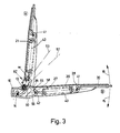
- the wiper arm shown in FIG. 3 is constructed in the same way as the first wiper arm shown and described except for the retention of the articulation point 42 of the spring element 40 on the bracket 50.
- the differently constructed device 60 ' which functions in the same way as the device 60, is described below.
- the device 60 ' is composed of a kink 26 which is embedded in the joint part back 21 and projects into the joint part interior and which cooperates with the front end 58 which is curved toward the pivot axis 13 and which is approximately C-shaped in the longitudinal direction of the wiper arm 50.
- the kink 26 already begins relatively far forward in the joint part back 21 approximately above the articulation point 41 of the tension spring 40 on the joint part 20 at an area marked with 28. As a result, the transition from the normal to the kinked area is smooth and does not pose any manufacturing difficulties.
- the front end 58 of the bracket 50 is covered with a plastic cap 55 with good sliding properties.
Landscapes
- Engineering & Computer Science (AREA)
- Mechanical Engineering (AREA)
- Pivots And Pivotal Connections (AREA)
Applications Claiming Priority (2)
| Application Number | Priority Date | Filing Date | Title |
|---|---|---|---|
| DE3530108 | 1985-08-23 | ||
| DE19853530108 DE3530108C1 (de) | 1985-08-23 | 1985-08-23 | Wischarm,insbesondere fuer Kraftfahrzeug-Scheibenwischeranlagen |
Publications (1)
| Publication Number | Publication Date |
|---|---|
| EP0216110A1 true EP0216110A1 (fr) | 1987-04-01 |
Family
ID=6279153
Family Applications (1)
| Application Number | Title | Priority Date | Filing Date |
|---|---|---|---|
| EP86111208A Withdrawn EP0216110A1 (fr) | 1985-08-23 | 1986-08-13 | Bras d'essuie-glace, notamment pour installations d'essuie-glace de véhicule automobile |
Country Status (3)
| Country | Link |
|---|---|
| EP (1) | EP0216110A1 (fr) |
| JP (1) | JPS6246743A (fr) |
| DE (1) | DE3530108C1 (fr) |
Families Citing this family (5)
| Publication number | Priority date | Publication date | Assignee | Title |
|---|---|---|---|---|
| DE3724777A1 (de) * | 1987-07-25 | 1989-02-09 | Swf Auto Electric Gmbh | Wischarm, insbesondere fuer kraftfahrzeug-scheibenwischeranlagen |
| JPH022922U (fr) * | 1988-06-02 | 1990-01-10 | ||
| DE19938969A1 (de) * | 1999-08-17 | 2001-02-22 | Bosch Gmbh Robert | Vorrichtung zum Befestigen eines Wischarms auf einer Antriebswelle |
| DE19951440B4 (de) * | 1999-10-25 | 2015-04-02 | Robert Bosch Gmbh | Wischarm für ein Fahrzeug |
| JP5780564B2 (ja) * | 2014-02-19 | 2015-09-16 | 日本ワイパブレード株式会社 | ワイパーアーム |
Citations (2)
| Publication number | Priority date | Publication date | Assignee | Title |
|---|---|---|---|---|
| US2847695A (en) * | 1954-07-16 | 1958-08-19 | Gen Motors Corp | Windshield wiper arm |
| DE2105101B2 (de) * | 1971-02-04 | 1973-01-18 | Vorrichtung zum befestigen eines scheibenwischarmes auf einer antriebswelle, insbesondere fuer kraftfahrzeuge |
Family Cites Families (1)
| Publication number | Priority date | Publication date | Assignee | Title |
|---|---|---|---|---|
| DE606116C (de) * | 1931-08-13 | 1934-11-24 | Emile Brumm | Scheibenwischer |
-
1985
- 1985-08-23 DE DE19853530108 patent/DE3530108C1/de not_active Expired
-
1986
- 1986-08-13 EP EP86111208A patent/EP0216110A1/fr not_active Withdrawn
- 1986-08-22 JP JP61197024A patent/JPS6246743A/ja active Pending
Patent Citations (2)
| Publication number | Priority date | Publication date | Assignee | Title |
|---|---|---|---|---|
| US2847695A (en) * | 1954-07-16 | 1958-08-19 | Gen Motors Corp | Windshield wiper arm |
| DE2105101B2 (de) * | 1971-02-04 | 1973-01-18 | Vorrichtung zum befestigen eines scheibenwischarmes auf einer antriebswelle, insbesondere fuer kraftfahrzeuge |
Also Published As
| Publication number | Publication date |
|---|---|
| DE3530108C1 (de) | 1986-12-11 |
| JPS6246743A (ja) | 1987-02-28 |
Similar Documents
| Publication | Publication Date | Title |
|---|---|---|
| DE69002714T2 (de) | Beweglicher Luftableiter für Scheibenwischerblatt, insbesondere für Kraftfahrzeug. | |
| DE1905352A1 (de) | Scheibenwischer,insbesondere fuer Kraftfahrzeuge mit einem schwenkbaren Wischarm | |
| DE112017002548T5 (de) | Fahrzeugwischervorrichtung | |
| DE3433106C2 (de) | Wischarm, insbesondere für Wischanlagen an Kraftfahrzeugen | |
| DE19951440B4 (de) | Wischarm für ein Fahrzeug | |
| EP0301131B1 (fr) | Bras d'essuyage, notamment pour installations d'essuie-glace de véhicules automobiles | |
| DE3132183C2 (fr) | ||
| EP0324926B1 (fr) | Rétroviseur extérieur rabattable pour un véhicule | |
| DE2812413A1 (de) | Scheibenwischer, insbesondere fuer kraftfahrzeuge | |
| DE3521527C2 (de) | Wischarm, insbesondere für Scheibenreinigungsanlagen für Kraftfahrzeuge | |
| DE19702701A1 (de) | Kraftfahrzeugscheibenwischer mit einer Abdeckkappe, die an einem Anschlußstück für die Anlenkung des Wischblatts am Wischerarm angebracht ist | |
| DE3619589C2 (de) | Wischblatt für Scheibenreinigungsanlagen an Fahrzeugen, insbesondere an Kraftfahrzeugen | |
| DE69705138T2 (de) | Scheibenwischer für Kraftfahrzeuge mit Verkleidung für Endstück | |
| DE2239643C3 (de) | Scheibenwischereinrichtung für Kraftfahrzeuge | |
| DE69709614T2 (de) | Scheibenwischerarm | |
| DE3530108C1 (de) | Wischarm,insbesondere fuer Kraftfahrzeug-Scheibenwischeranlagen | |
| DE19745846A1 (de) | Lagerteil zum Anlenken eines Wischerblatts | |
| EP0337364A2 (fr) | Rétroviseur extérieur rabattable pour véhicules | |
| DE4211326A1 (de) | Wischarm für Scheibenwischer von Kraftfahrzeugen | |
| DE3714651A1 (de) | Wischarm, insbesondere fuer scheibenwischeranlagen an kraftfahrzeugen | |
| EP0221255A2 (fr) | Rétroviseur pour véhicule | |
| EP1641664A1 (fr) | Bras d'essuie-glace | |
| DE2352777A1 (de) | Loesbare verbindung zwischen dem wischblatt und dem wischarm einer scheibenwischanlage | |
| DE69304147T2 (de) | Scheibenwischer mit Abdeckkappe, die am Befestigungsstift der Anpressfeder schwenkbar gelagert ist | |
| DE69500448T2 (de) | Kraftfahrzeugscheibenwischer mit aerodynamischem Windabweiser |
Legal Events
| Date | Code | Title | Description |
|---|---|---|---|
| PUAI | Public reference made under article 153(3) epc to a published international application that has entered the european phase |
Free format text: ORIGINAL CODE: 0009012 |
|
| AK | Designated contracting states |
Kind code of ref document: A1 Designated state(s): FR GB IT |
|
| 17P | Request for examination filed |
Effective date: 19870919 |
|
| 17Q | First examination report despatched |
Effective date: 19880502 |
|
| STAA | Information on the status of an ep patent application or granted ep patent |
Free format text: STATUS: THE APPLICATION IS DEEMED TO BE WITHDRAWN |
|
| 18D | Application deemed to be withdrawn |
Effective date: 19881220 |
|
| RIN1 | Information on inventor provided before grant (corrected) |
Inventor name: BAUER, KURT Inventor name: DOERR, WILHELM |