EP0337364A2 - Rétroviseur extérieur rabattable pour véhicules - Google Patents
Rétroviseur extérieur rabattable pour véhicules Download PDFInfo
- Publication number
- EP0337364A2 EP0337364A2 EP89106344A EP89106344A EP0337364A2 EP 0337364 A2 EP0337364 A2 EP 0337364A2 EP 89106344 A EP89106344 A EP 89106344A EP 89106344 A EP89106344 A EP 89106344A EP 0337364 A2 EP0337364 A2 EP 0337364A2
- Authority
- EP
- European Patent Office
- Prior art keywords
- mirror
- mirror housing
- rocker
- cap
- housing
- Prior art date
- Legal status (The legal status is an assumption and is not a legal conclusion. Google has not performed a legal analysis and makes no representation as to the accuracy of the status listed.)
- Granted
Links
Images


Classifications
-
- B—PERFORMING OPERATIONS; TRANSPORTING
- B60—VEHICLES IN GENERAL
- B60R—VEHICLES, VEHICLE FITTINGS, OR VEHICLE PARTS, NOT OTHERWISE PROVIDED FOR
- B60R1/00—Optical viewing arrangements; Real-time viewing arrangements for drivers or passengers using optical image capturing systems, e.g. cameras or video systems specially adapted for use in or on vehicles
- B60R1/02—Rear-view mirror arrangements
- B60R1/06—Rear-view mirror arrangements mounted on vehicle exterior
- B60R1/076—Rear-view mirror arrangements mounted on vehicle exterior yieldable to excessive external force and provided with an indexed use position
Definitions
- the invention relates to an exterior mirror for vehicles with a mirror base that can be attached to the body of the vehicle and a mirror housing that is held in the position of use on the mirror base with spring force, wherein an edge of the mirror housing rests on a shoulder of the mirror base and the mirror housing around its rear edge section in the direction of travel against the spring force is pivotable backwards relative to the mirror base.
- the driver must push the swivel arm backwards out of the locking position. This can result in a safety risk for the driver insofar as his fingers can be pinched between the front edge of the mirror housing and the mirror base when the mirror housing is folded back into the position of use under the effect of a tension spring which is usually designed to be strong.
- a releasable locking device between the mirror housing and the mirror base is provided to reduce this safety risk, which on the one hand holds the mirror housing in the pivoted end position and defines it on the other hand, can be solved by a slight impact on the outer edge of the mirror housing, so that the driver is no longer forced to intervene with his hands in the opening between the folded mirror housing and the mirror base.
- the opening between the front edge of the mirror housing and the mirror base remains freely accessible when the mirror housing is folded back.
- the locking mechanism intervenes in the opening by trusting that the mirror housing is securely held in the swivel end position.
- foreign particles or water from washing systems are introduced into the area between the mirror base and the mirror housing after the mirror housing has been folded onto the vehicle body.
- the invention is therefore based on the object to provide a cover for the opening between the mirror housing and the mirror base in an outside mirror, which can be advantageously made of the same material as the mirror housing, therefore is resistant to aging and largely precludes manual access to the opening.
- an edge of the mirror housing resting on a shoulder of the mirror base and the mirror housing around its rear edge section in the direction of travel against the spring force relative to Mirror base is pivotable to the rear, is provided according to the invention to solve the problem that a curved, in the use position enclosed by the mirror housing cap is attached, the curvature of which is centered on the rear edge portion and against the outer contour of the mirror housing at its front edge portion when pivoting is present.
- the cap remains free from the weather when the mirror housing is in use and also does not appear aesthetically.
- the cap can be made from a simple molded plastic part. Finally, it enables the opening between the mirror housing and mirror base to be fully covered when the former is pivoted away.
- the mirror housing can also be swiveled forward relative to the mirror base in a conventional manner, it is advisable in a further development of the invention to link the cap near a front shoulder section on the mirror base and either press it against the mirror housing by means of a spring or to provide a foot on the cap with which it is supported on the mirror base when swiveling backwards.
- link the cap near a front shoulder section on the mirror base and either press it against the mirror housing by means of a spring or to provide a foot on the cap with which it is supported on the mirror base when swiveling backwards.
- a locking member can be formed on the cap, which detachably grips the mirror housing in a rear pivoting end position with respect to the direction of travel.
- This blocking organ can be integrated into the cap shape in that a nose protruding from the outer contour of the cap is provided, which underlies the front edge section in the pivot end position. From the defined swivel end position, the mirror housing can then be freed from the driver's seat by a light impact on the outer parts of the mirror housing, whereupon the mirror housing is automatically pivoted back into its position of use by the tension spring.
- the locking member can be a paragraph of the mirror housing locking bolt, which is fastened within the cap and protrudes little from an opening of the cap, whereby to facilitate the pivoting movement of the mirror housing backwards the bolt can dodge backwards against spring pressure.
- the locking member is in the form of a rocker, which is held by a spring in one of two tilt positions.
- a catch formed on the rocker or the mirror housing falls into a trap and in this way holds the pivoted mirror housing in the pivot end position.
- the mirror housing is pivoted a short distance further to the vehicle body, whereby the rocker is transferred to its second tilt position, in which the catch is released from the trap, so that the mirror housing can be returned to its position of use by the tension spring.
- the mirror housing changes the rocker in its first tilt position, so that it is prepared for locking the mirror housing in its rear swiveling end position.
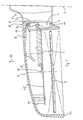
- FIG. 1 first shows an exterior mirror of a known type.
- a mirror base 2 is fastened to a vehicle body 1, shown schematically in dashed lines, in a manner not shown.
- the mirror base 2 On the side facing away from the vehicle body 1, the mirror base 2 has one Mounting plate 4, which, offset from the vehicle body 1, is surrounded by a shoulder 3 which extends around the mounting plate 4 and projects outwards.
- a mirror housing 5 has an edge 18 which is spherically shaped at the end near the mirror base, of which the front edge section 6 and the rear edge section 8 can be seen in FIG. 1.
- the designations "front” and “rear” refer to the direction of travel of the vehicle indicated by arrow 10.
- the edge sections 6, 8 encompass the mounting plate 4 and stand in the position of use of the mirror housing 5 shown in FIG. 1 on corresponding parts of the shoulder 3.
- a strong tension spring 7 is fastened, the end of which is located in the mirror housing 5 is suspended in an eyelet 11 of a support plate 15.
- the support plate 15 is fastened to the front wall 13 of the mirror housing 5 via supports, of which a support 14 remote from the mirror base is indicated in FIG. 1.
- a mirror glass 9 is held on the support plate 15 in a customary manner by means of actuators from the vehicle interior, not shown, which extend through the mirror base 2 and an opening 16 in the mirror housing 5.
- an arm extending into the interior of the mirror housing 5 is articulated on the mounting plate 4 and is held against the inside of the wall 13 by a spring 17.
- a cap designated as a whole by 20 is within the edge 18 in a region of the mounting plate 4 of the mirror base 2 articulated, which is adjacent to the front edge portion 6.
- the mounting plate 4 has a cutout 41, into which a lower end 21 of the cap 20 protrudes and is pivotably held there on a pin 42 about an axis which is perpendicular to the plane of FIG. 2 and is therefore essentially vertical with the exterior mirror mounted on the vehicle is.
- the cap 20, which is a one-piece component and is made of the same plastic as the mirror housing 5, has a curved or curved shape, the curvature of which is centered on the rear edge section 8.
- the shell shape of the cap 20 depends in particular on the outer shape of the edge 18 in such a way that the outer contour 22 of the cap 20 is defined by the shape of the path through which the front edge portion 6 travels when the mirror housing 5 is pivoted backwards.
- An inner thickening 23 is formed on the cap 20 and has a pocket 24 for receiving and holding a compression spring 25.
- the compression spring 25 projects with its free end out of the pocket 24 and can be supported on the top of the mounting plate 4 of the mirror base 2.
- a nose 26 projects outwards, the function of which will be explained below.
- an armature 43 with an eye 44 protrudes toward the mirror housing 5 from the mounting plate 4 approximately in the center.
- the end 19 of the tension spring 7 near the mirror base is suspended in the eye 44.
- a pin-shaped extension 81 is formed on the rear edge section 8, which extends into a rear cutout 45 in the rear side flank of the mounting plate 4.
- the assembly comprising the cap 20 and the compression spring 25 is entirely from the edge 18 of the mirror housing 5 and therefore not visible from the outside.
- the front edge section 6 slides along a first part 27 of the outer contour 22, which is opposite the surrounding one Part 28 of the outer contour projects like a rib with increasing thickness and ends in the nose 26. While the front edge section 6 is sliding along, the cap 20 is pressed around the pin 42 in the direction of the mounting plate 4 against the action of the compression spring 25 which is then supported thereon.
- the cap 20 jumps forward so far that the upper part 29 of its outer contour 22 now lies against the edge 18 from the inside.
- the penetration of the extension 81 through the cutout 45 into the mirror base 2 secures the mirror housing 5 against a displacement relative to the mirror base 2 downwards or upwards.
- the mirror housing 5 can now only return in the direction of its position of use under the action of the tension spring 7 up to its rear pivot end position shown in FIG. 3, which is determined by gripping the front edge section 6 through the nose 26.
- the mirror housing can be released by a short blow or pressure by hand on its outer part 51, as a result of which the front edge section 6 is lifted outward beyond the nose 26, which is made possible by a corresponding size of the rear cutout 45. Thereafter, the mirror housing 5 can automatically return to the position of use shown in FIG. 2 under the action of the tension spring 7.
- the shape of the cap is largely closed by the cap 20.
- the lateral expansion of the cap 20 is not subject to any restrictions, so that it can be chosen so large that the said opening remains practically completely closed from the outside up to the rear swivel end position.
- the rear edge section 8 with extension 81 lifts off the rear part of the shoulder 3, while the front edge section 6 rolls on the front part of the shoulder 3.
- the cap 20 is pivoted forward by the tension spring 7 during this forward pivoting movement, but otherwise does not interfere with the inevitable movements of the tension spring and the other adjusting elements for the mirror 9.
- FIGS. 5 and 6 differs from the first embodiment described above in that, instead of the nose protruding from the outer contour 22 of the cap 20, a separate latch 30 is provided, which essentially rests on the pin 42 parallel shaft 31 is pivotally mounted.
- the bolt 30 runs up to a narrow ridge 32 which protrudes into a groove 33 recessed into the outer contour 34.
- An apron 35 extends from the bolt 30 at the end facing away from the ridge 32 in the direction of the mounting plate 4.
- a bracket 46 protruding from the mounting plate 4 a depression 46 is formed, the opening of which points to the apron 35.
- a pressure spring 36 is accommodated in the depression 47, which is supported on the bottom of the depression 47 and bears against the apron 35.
- the height of the bracket 46 above the mounting plate 4 is selected so that a shoulder 37, which is formed on the bolt 30 between the shaft 31 and the cap 38, in the locking position of the bolt 30 on the top of the bracket 46 shown in FIG. 5 sits as a stop.
- the cap 38 is slotted at 39 in the upper region of the channel 33, otherwise resembles the cap 20 from the first exemplary embodiment.
- the mirror housing 5 has within its front edge portion 6 an inwardly projecting shoulder 61 which projects so far that it is completely immersed in the groove 31 and in the rear pivot end position can be engaged by the bolt 30 with the ridge 32.
- the inside of the nose 61 which is of course not wider than the width of the groove 33, first steers the latch 30 backwards against the action of the spring 36 until the latch 30 in the locking position shown in Fig. 5 can protrude behind the shoulder 61.
- the pivoted mirror housing 5 can then only return to its use position up to the rear pivot end position shown in FIG. 5, in which the shoulder 61 bears against the ridge 32.
- To release the nose 61 is lifted over the ridge 32 by manual pressure on the portion 51 of the mirror housing, so that the mirror housing can return to its position of use.
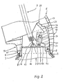
- the cap 50 is designed essentially the same as the cap 20, but has a slot 52 in the region of the trough 33 from the second embodiment is tiltably mounted on a shaft 72.
- the shaft 72 is supported on trestles 73, which protrude from the mounting plate 4 behind the cap 50 in the direction of the mirror housing 5.
- a spring 74 is held at its end near the mirror base on a pin 48 fastened to the mirror base and is suspended with its end near the rocker in a bore 76 in the central part 75 of the rocker 70.
- the rocker 70 is provided with a transverse slot 77, in which the shaft 72 is captured.
- the transverse slot extends transversely to the line of action 78 of the spring 74 in a manner to be described.
- the rocker 70 has a first arm 66 which has an opening 67 near its free end.
- the opening 67 serves as a trap for a locking lug 68 which protrudes from the inside of the front edge section 6 of the mirror housing 5.
- the rocker 70 has a second arm 62, which is opposite the first arm 66 with respect to the central part 75 and dips with its free end into the slot 52.
- FIG. 7 shows the mirror housing 5 in the rear swivel end position, in which the latch 68 is caught in the latch 67 and is supported on the shaft 72 via the first arm 66 and the end of the transverse slot 77 adjacent to the arm 66.
- the mirror housing 5 is held securely in the rear swivel end position.
- the line of action 78 of the spring 74 extends to the right of the shaft 72 as shown in FIG. 7, so that the spring 74 exerts a clockwise torque on the rocker 70, thus holding the first arm 66 against the inside of the front edge section 6.
- the mirror housing 5 is pivoted further back.
- the detent 68 takes the rocker 70 along in such a way that the rocker 70 is pulled over the shaft 72 until the shaft 72 rests on the opposite end of the transverse slot 77.
- the line of action 78 passes through the shaft 72, so that after passing the spring 74 exerts a torque on the rocker 70 in the counterclockwise direction.
- the rocker 70 pivots from the first, locking tilting position shown in FIG. 7 into a second, not shown tilting position under the action of the spring 74.
- the first arm 66 is pulled off the locking lug 68, so that the mirror housing 5 can now freely return to its position of use under the action of the tension spring 7.
- the front edge section 6 sets in on its return path from the region of the rear pivot end position the position of use by taking the second arm 62 with the rocker 70 back into the first tilt position, in which the first arm 66 abuts against the mirror housing 5 from the inside.
- the mirror housing 5 can then pivot back again, the locking lug 68 moving along in the slot 52 and deflecting the rocker 70 against the action of the spring 74 until the locking lug 68 has fallen into the latch 67.
- the transverse slot 67 at the end at which the spring 74 exerts a clockwise torque on the rocker 70 is widened like a bag at 71.
- This measure means that a certain force is required to take the rocker 70 through the mirror housing 5 from the first tilt position shown in FIG. 7, which force can be easily applied by pivoting the mirror housing 5 further towards the vehicle from the rear pivot end position , but prevents the rocker 70 from being taken against the first arm 66 when the latch 68 starts when the mirror housing 5 is pivoted back.
- Fig. 9 shows a modification of the rocker 70 on the first arm 66. Thereafter, the free end of the first arm of the rocker 54 is cranked outwards at 57, which forms a type of locking lug. Correspondingly, a pocket-shaped trap 58 is cut into the front edge section 6 from the inside, into which the first arm 56 of the rocker 54 can dip. The operation of the rocker 54 is otherwise the same as that of the rocker 70.
- brackets 46, 73 on the associated cap 38, 50 and to anchor the spring 74 on a pin 48 which is also mounted in the cap 50. This creates an assembly consisting of a cap and locking member, which is mounted separately from the outside mirror and can then be used as a whole in the outside mirror.
Landscapes
- Engineering & Computer Science (AREA)
- Multimedia (AREA)
- Mechanical Engineering (AREA)
- Rear-View Mirror Devices That Are Mounted On The Exterior Of The Vehicle (AREA)
- Mirrors, Picture Frames, Photograph Stands, And Related Fastening Devices (AREA)
Applications Claiming Priority (2)
| Application Number | Priority Date | Filing Date | Title |
|---|---|---|---|
| DE8804802U DE8804802U1 (de) | 1988-04-12 | 1988-04-12 | Abklappbarer Außenspiegel für Fahrzeuge |
| DE8804802U | 1988-04-12 |
Publications (3)
| Publication Number | Publication Date |
|---|---|
| EP0337364A2 true EP0337364A2 (fr) | 1989-10-18 |
| EP0337364A3 EP0337364A3 (fr) | 1991-02-06 |
| EP0337364B1 EP0337364B1 (fr) | 1994-09-28 |
Family
ID=6822836
Family Applications (1)
| Application Number | Title | Priority Date | Filing Date |
|---|---|---|---|
| EP89106344A Expired - Lifetime EP0337364B1 (fr) | 1988-04-12 | 1989-04-11 | Rétroviseur extérieur rabattable pour véhicules |
Country Status (7)
| Country | Link |
|---|---|
| US (1) | US4907869A (fr) |
| EP (1) | EP0337364B1 (fr) |
| AT (1) | ATE112215T1 (fr) |
| CA (1) | CA1322681C (fr) |
| DE (2) | DE8804802U1 (fr) |
| ES (1) | ES2060683T3 (fr) |
| MX (1) | MX171658B (fr) |
Cited By (2)
| Publication number | Priority date | Publication date | Assignee | Title |
|---|---|---|---|---|
| US5549481A (en) * | 1993-06-04 | 1996-08-27 | Framatome Connectors International | Connector assembly for printed circuit boards |
| DE29620696U1 (de) * | 1996-11-28 | 1998-04-02 | Hohe GmbH & Co. KG, 97903 Collenberg | Außenspiegel für ein Kraftfahrzeug |
Families Citing this family (8)
| Publication number | Priority date | Publication date | Assignee | Title |
|---|---|---|---|---|
| DE8813505U1 (de) * | 1988-10-27 | 1989-03-23 | Hohe Kg, 6981 Collenberg | Abklappbarer Außenspiegel für Fahrzeuge |
| FR2642380B1 (fr) * | 1989-01-27 | 1994-06-24 | Harman Automative | Retroviseur rabattable en position de stationnement et en position d'ejection |
| DE8913032U1 (de) * | 1989-11-04 | 1990-03-22 | Eugen Zipperle GmbH & Co KG, 7144 Asperg | Außenspiegel für Kraftfahrzeuge |
| DE4017028C2 (de) * | 1990-05-26 | 1993-10-21 | Zipperle Eugen Gmbh & Co Kg | Außenspiegel für Kraftfahrzeuge |
| ES2029188A6 (es) * | 1991-03-13 | 1992-07-16 | Fico Mirrors Sa | Mecanismo de abatimiento para espejos retrovisores exteriores de vehiculos automoviles. |
| US5477391A (en) * | 1993-08-16 | 1995-12-19 | Lowell Engineering Corp. | Mirror assembly movable into rearwardly folded position with reversing spring bias |
| US5477390A (en) * | 1993-08-16 | 1995-12-19 | Lowell Engineering Corp. | Mirror assembly powered into rearwardly folded position against reversing spring bias |
| US6733144B2 (en) * | 2002-09-27 | 2004-05-11 | Intel Corporation | Shock protectors for micro-mechanical systems |
Family Cites Families (4)
| Publication number | Priority date | Publication date | Assignee | Title |
|---|---|---|---|---|
| DE3032392C2 (de) * | 1980-08-28 | 1982-09-23 | Hohe Kg, 6981 Collenberg | Außenspiegel für Fahrzeuge |
| DE3220893A1 (de) * | 1982-06-03 | 1983-12-08 | Hohe Kg, 6981 Collenberg | Aussenspiegel mit rueckhaltehebel fuer fahrzeuge |
| GB8525778D0 (en) * | 1985-10-18 | 1985-11-20 | Britax Wingard Ltd | Exterior rear view mirrors |
| DE8711959U1 (de) * | 1987-09-03 | 1987-12-23 | Hohe Kg, 6981 Collenberg | Außenspiegel für ein Fahrzeug mit einem Spiegelfuß und einem relativ zum Spiegelfuß aus einer Gebrauchslage nach vorne und hinten abklappbaren Spiegelgehäuse |
-
1988
- 1988-04-12 DE DE8804802U patent/DE8804802U1/de not_active Expired
-
1989
- 1989-04-11 US US07/336,123 patent/US4907869A/en not_active Expired - Lifetime
- 1989-04-11 EP EP89106344A patent/EP0337364B1/fr not_active Expired - Lifetime
- 1989-04-11 DE DE58908427T patent/DE58908427D1/de not_active Expired - Fee Related
- 1989-04-11 ES ES89106344T patent/ES2060683T3/es not_active Expired - Lifetime
- 1989-04-11 AT AT89106344T patent/ATE112215T1/de not_active IP Right Cessation
- 1989-04-12 MX MX015636A patent/MX171658B/es unknown
- 1989-04-12 CA CA000596501A patent/CA1322681C/fr not_active Expired - Fee Related
Cited By (2)
| Publication number | Priority date | Publication date | Assignee | Title |
|---|---|---|---|---|
| US5549481A (en) * | 1993-06-04 | 1996-08-27 | Framatome Connectors International | Connector assembly for printed circuit boards |
| DE29620696U1 (de) * | 1996-11-28 | 1998-04-02 | Hohe GmbH & Co. KG, 97903 Collenberg | Außenspiegel für ein Kraftfahrzeug |
Also Published As
| Publication number | Publication date |
|---|---|
| US4907869A (en) | 1990-03-13 |
| EP0337364B1 (fr) | 1994-09-28 |
| DE8804802U1 (de) | 1988-09-01 |
| MX171658B (es) | 1993-11-10 |
| ATE112215T1 (de) | 1994-10-15 |
| EP0337364A3 (fr) | 1991-02-06 |
| DE58908427D1 (de) | 1994-11-03 |
| CA1322681C (fr) | 1993-10-05 |
| ES2060683T3 (es) | 1994-12-01 |
Similar Documents
| Publication | Publication Date | Title |
|---|---|---|
| DE2655535C3 (de) | Gelenkbeschlag für Kraftfahrzeugsitze | |
| DE69011403T2 (de) | Wischerblattanordnung. | |
| DE4331884B4 (de) | Abdeckeinrichtung für einen Kosmetikspiegel | |
| DE2760301C2 (de) | Fersenhalter | |
| DE3444216C2 (de) | Kopfstütze | |
| DE69403683T2 (de) | Verbindungs-und Gelenkeinrichtung zur Befestigung eines Scheibenwischblatts an einem Wischarm | |
| EP0337364B1 (fr) | Rétroviseur extérieur rabattable pour véhicules | |
| EP0393586A1 (fr) | Dispositif de fixation d'une chaussure sur une pédale de bicyclette | |
| DE3325833A1 (de) | Tuerspiegelvorrichtung fuer automobile | |
| DE2904616A1 (de) | Vorrichtung zum festhalten der tuer eines kraftfahrzeugs | |
| EP0324926B1 (fr) | Rétroviseur extérieur rabattable pour un véhicule | |
| DE2309956C2 (de) | Schnäpperscharnier für Möbeltüren | |
| EP0190715B1 (fr) | Porte à battants pour véhicule | |
| EP0936131B1 (fr) | Dispositif de basculement pour cabines suspendues de camions | |
| DE3390395T1 (de) | Scheibenwischersystem mit am Wischblatt mittels Adapter befestigter Wippvorrichtung | |
| EP0297284A2 (fr) | Rétroviseur extérieur | |
| DE2727948A1 (de) | Fahrzeugsitz | |
| DE3231418C2 (de) | Sicherungsvorrichtung an Fahrzeugen zum Sichern einer in den Bereich eines Füllstutzens eines Kraftstofftanks verschiebbaren Schiebetür während des Tankens | |
| DE69500850T2 (de) | Scheibenwischer für Kraftfahrzeug | |
| DE2723073C2 (fr) | ||
| DE19526317A1 (de) | Vorrichtung für die Längsverstellung eines Kraftfahrzeugsitzes | |
| EP0216110A1 (fr) | Bras d'essuie-glace, notamment pour installations d'essuie-glace de véhicule automobile | |
| DE2406381A1 (de) | Abblendbarer innenrueckblickspiegel | |
| DE3609449A1 (de) | Innenrueckblickspiegel fuer kraftfahrzeuge | |
| DE2223514A1 (de) | Oberkantenhalterung fuer einen fluegel eines fensters, einer tuer od. dgl |
Legal Events
| Date | Code | Title | Description |
|---|---|---|---|
| PUAI | Public reference made under article 153(3) epc to a published international application that has entered the european phase |
Free format text: ORIGINAL CODE: 0009012 |
|
| AK | Designated contracting states |
Kind code of ref document: A2 Designated state(s): AT BE CH DE ES FR GB IT LI LU NL SE |
|
| PUAL | Search report despatched |
Free format text: ORIGINAL CODE: 0009013 |
|
| AK | Designated contracting states |
Kind code of ref document: A3 Designated state(s): AT BE CH DE ES FR GB IT LI LU NL SE |
|
| 17P | Request for examination filed |
Effective date: 19910724 |
|
| 17Q | First examination report despatched |
Effective date: 19920930 |
|
| GRAA | (expected) grant |
Free format text: ORIGINAL CODE: 0009210 |
|
| AK | Designated contracting states |
Kind code of ref document: B1 Designated state(s): AT BE CH DE ES FR GB IT LI LU NL SE |
|
| REF | Corresponds to: |
Ref document number: 112215 Country of ref document: AT Date of ref document: 19941015 Kind code of ref document: T |
|
| REF | Corresponds to: |
Ref document number: 58908427 Country of ref document: DE Date of ref document: 19941103 |
|
| GBT | Gb: translation of ep patent filed (gb section 77(6)(a)/1977) |
Effective date: 19941027 |
|
| REG | Reference to a national code |
Ref country code: ES Ref legal event code: FG2A Ref document number: 2060683 Country of ref document: ES Kind code of ref document: T3 |
|
| ET | Fr: translation filed | ||
| ITF | It: translation for a ep patent filed | ||
| EAL | Se: european patent in force in sweden |
Ref document number: 89106344.8 |
|
| PG25 | Lapsed in a contracting state [announced via postgrant information from national office to epo] |
Ref country code: LU Free format text: LAPSE BECAUSE OF NON-PAYMENT OF DUE FEES Effective date: 19950430 Ref country code: LI Effective date: 19950430 Ref country code: CH Effective date: 19950430 |
|
| PLBE | No opposition filed within time limit |
Free format text: ORIGINAL CODE: 0009261 |
|
| STAA | Information on the status of an ep patent application or granted ep patent |
Free format text: STATUS: NO OPPOSITION FILED WITHIN TIME LIMIT |
|
| 26N | No opposition filed | ||
| REG | Reference to a national code |
Ref country code: CH Ref legal event code: PL |
|
| PGFP | Annual fee paid to national office [announced via postgrant information from national office to epo] |
Ref country code: FR Payment date: 19970417 Year of fee payment: 9 |
|
| PGFP | Annual fee paid to national office [announced via postgrant information from national office to epo] |
Ref country code: SE Payment date: 19970422 Year of fee payment: 9 Ref country code: BE Payment date: 19970422 Year of fee payment: 9 |
|
| PGFP | Annual fee paid to national office [announced via postgrant information from national office to epo] |
Ref country code: GB Payment date: 19970423 Year of fee payment: 9 Ref country code: AT Payment date: 19970423 Year of fee payment: 9 |
|
| PGFP | Annual fee paid to national office [announced via postgrant information from national office to epo] |
Ref country code: NL Payment date: 19970429 Year of fee payment: 9 |
|
| PGFP | Annual fee paid to national office [announced via postgrant information from national office to epo] |
Ref country code: ES Payment date: 19970430 Year of fee payment: 9 Ref country code: DE Payment date: 19970430 Year of fee payment: 9 |
|
| PG25 | Lapsed in a contracting state [announced via postgrant information from national office to epo] |
Ref country code: GB Free format text: LAPSE BECAUSE OF NON-PAYMENT OF DUE FEES Effective date: 19980411 Ref country code: AT Free format text: LAPSE BECAUSE OF NON-PAYMENT OF DUE FEES Effective date: 19980411 |
|
| PG25 | Lapsed in a contracting state [announced via postgrant information from national office to epo] |
Ref country code: SE Free format text: LAPSE BECAUSE OF NON-PAYMENT OF DUE FEES Effective date: 19980412 |
|
| PG25 | Lapsed in a contracting state [announced via postgrant information from national office to epo] |
Ref country code: ES Free format text: LAPSE BECAUSE OF NON-PAYMENT OF DUE FEES Effective date: 19980413 |
|
| PG25 | Lapsed in a contracting state [announced via postgrant information from national office to epo] |
Ref country code: FR Free format text: THE PATENT HAS BEEN ANNULLED BY A DECISION OF A NATIONAL AUTHORITY Effective date: 19980430 Ref country code: BE Free format text: LAPSE BECAUSE OF NON-PAYMENT OF DUE FEES Effective date: 19980430 |
|
| BERE | Be: lapsed |
Owner name: HOHE K.G. Effective date: 19980430 |
|
| PG25 | Lapsed in a contracting state [announced via postgrant information from national office to epo] |
Ref country code: NL Free format text: LAPSE BECAUSE OF NON-PAYMENT OF DUE FEES Effective date: 19981101 |
|
| GBPC | Gb: european patent ceased through non-payment of renewal fee |
Effective date: 19980411 |
|
| NLV4 | Nl: lapsed or anulled due to non-payment of the annual fee |
Effective date: 19981101 |
|
| EUG | Se: european patent has lapsed |
Ref document number: 89106344.8 |
|
| PG25 | Lapsed in a contracting state [announced via postgrant information from national office to epo] |
Ref country code: DE Free format text: LAPSE BECAUSE OF NON-PAYMENT OF DUE FEES Effective date: 19990202 |
|
| REG | Reference to a national code |
Ref country code: FR Ref legal event code: ST |
|
| REG | Reference to a national code |
Ref country code: ES Ref legal event code: FD2A Effective date: 20010503 |
|
| PG25 | Lapsed in a contracting state [announced via postgrant information from national office to epo] |
Ref country code: IT Free format text: LAPSE BECAUSE OF NON-PAYMENT OF DUE FEES Effective date: 20050411 |