EP0216328A2 - Système de bouche de soufflage d'air pour la ventilation d'une pièce - Google Patents
Système de bouche de soufflage d'air pour la ventilation d'une pièce Download PDFInfo
- Publication number
- EP0216328A2 EP0216328A2 EP86112960A EP86112960A EP0216328A2 EP 0216328 A2 EP0216328 A2 EP 0216328A2 EP 86112960 A EP86112960 A EP 86112960A EP 86112960 A EP86112960 A EP 86112960A EP 0216328 A2 EP0216328 A2 EP 0216328A2
- Authority
- EP
- European Patent Office
- Prior art keywords
- supply air
- air outlet
- guide element
- room
- outlet system
- Prior art date
- Legal status (The legal status is an assumption and is not a legal conclusion. Google has not performed a legal analysis and makes no representation as to the accuracy of the status listed.)
- Granted
Links
Images
Classifications
-
- F—MECHANICAL ENGINEERING; LIGHTING; HEATING; WEAPONS; BLASTING
- F24—HEATING; RANGES; VENTILATING
- F24F—AIR-CONDITIONING; AIR-HUMIDIFICATION; VENTILATION; USE OF AIR CURRENTS FOR SCREENING
- F24F13/00—Details common to, or for air-conditioning, air-humidification, ventilation or use of air currents for screening
- F24F13/08—Air-flow control members, e.g. louvres, grilles, flaps or guide plates
-
- F—MECHANICAL ENGINEERING; LIGHTING; HEATING; WEAPONS; BLASTING
- F24—HEATING; RANGES; VENTILATING
- F24F—AIR-CONDITIONING; AIR-HUMIDIFICATION; VENTILATION; USE OF AIR CURRENTS FOR SCREENING
- F24F13/00—Details common to, or for air-conditioning, air-humidification, ventilation or use of air currents for screening
- F24F13/02—Ducting arrangements
- F24F13/06—Outlets for directing or distributing air into rooms or spaces, e.g. ceiling air diffuser
- F24F13/072—Outlets for directing or distributing air into rooms or spaces, e.g. ceiling air diffuser of elongated shape, e.g. between ceiling panels
Definitions
- the invention relates to a supply air outlet system and a method for room ventilation by means of at least one such supply air outlet system.
- a known supply air outlet system of this type (US Pat. No. 2,350,514) has supply air elements arranged in a row one behind the other.
- Each supply air element consists of a horizontal duct section which is connected in series with the duct sections of further such air outlet elements, so that the duct sections of all supply air elements forming a row form an elongated air duct which guides the supply air to be blown out through this supply air outlet system.
- each duct section has a slot-shaped air outlet running in its longitudinal direction on its underside. At a distance vertically below this air outlet there is a guide element which is triangular in cross section and extends over the length of the air outlet.
- This guide element is made of sheet metal in a roof shape with inclined sides inclined at an angle of approx. 90 ° to one another and vertical, flat end faces. Its through the top of the triangular cross section conditional longitudinal central edge extends horizontally and is directed upwards to the air outlet. The greatest width of this guide element present above the lower base plane of this guide element is greater than the width of the air outlet.
- This guide element can be adjusted in height and also set in different angular positions. In its central position, in which its base plane is directed horizontally, it splits the supply air flow flowing through the air outlet into two equal side streams, which mirror the vertical longitudinal center plane of the air guide element and flow obliquely downwards along the two side surfaces of the air guide element and over its outer longitudinal edges .
- This air outlet system exerts strong induction on the room air, since the two side streams suck in room air from the room area below the guide element by induction to a large extent and thus generate two mutually symmetrical, counter-rotating room air rollers below the guide element.
- the main flow is throttled so much by the slot bridge grille that the auxiliary flows flowing out through the auxiliary outlets flow out at such a high speed that they suck in and spread the slow main flow by induction. Since the main flow through the air outlet grille is greatly restricted, it is from the side of such a supply air box The amount of air that can be blown out is relatively small, so that high air exchange rates in the room cannot be achieved with justifiable economic outlay.
- This supply air outlet system is also not suitable for systems in which the room air and possibly also the supply air contain to a considerable extent impurities such as dust, fibers and the like, because there is a risk of the slot bridge perforated plate becoming blocked.
- the supply air outlet system is insensitive to contaminants such as dust, fibers and the like contained in the ambient air or supply air.
- supply air outlet systems for textile machine halls in which textile machines are in operation, have so far caused problems because fibers, dust, other textile residues and the like emanate from such machines to a considerable extent, which get into the room air and from the air flows in the room to the newly blown in Supply air through which it is carried to the machine and can cause interference or is harmful.
- the supply air can also often contain fibers and dust because it is often not or only partially or only roughly filtered for cost reasons.
- This supply air outlet system is structurally simple and inexpensive. There is no need for air outlet grilles. The entire supply air can be blown out in directed flows of relatively large cross sections, so that there is no risk of clogging by dust, fibers or the like, and this supply air outlet system is consequently also excellent for text machine rooms and other rooms in which the room air and / or supply air contaminants clog the air outlet grilles can contains, such as fibers, dust and the like.
- the supply air outlet system according to the invention is also low in induction for indoor air, i.e. the induction on indoor air caused by its supply air flows is relatively small.
- the two side flows in the area below the air guiding element do not generate room air rollers by induction, but instead suck by induction the neighboring blowing jets which are blown out obliquely downwards through the supply air passage of the guiding element and which in turn suck in the air blown approximately vertically downwards by induction.
- the supply air outlet system By means of the supply air outlet system according to the invention it is possible - even at relatively high blowing-out speeds of the supply air - to maintain non-disturbing, low flow velocities of the room air in the installation area of machines or areas where people stay. In spite of the low lack of induction on indoor air, this system also ensures good mixing of the supply air and indoor air and also allows compliance with small temperature differences of the room temperature to, for example, % 1K.
- This supply air outlet system is also particularly suitable for blowing out supply air which has a low temperature, the temperature of which is therefore lower than the room temperature. It is thus possible to provide the temperature of the supply air very considerably below the room air, for example up to 12 K lower temperature or even more.
- This supply air outlet system is also suitable for rooms of very different heights. In general, it can be used for room heights from 2.30 m to 8.00 m and in special cases also for lower or higher rooms.
- the supply air outlet system according to the invention can preferably only serve to blow out supply air into the room in question. However, it is also possible to introduce additional supply air into the room through other known supply air outlet devices.
- the throwing distances of the supply air flows which can be achieved with the supply air outlet system according to the invention can be approximately 2 to 8 m and possibly even less or more.
- This supply air outlet system is particularly suitable for arrangement on solid ceilings or false ceilings of rooms, but it may also have a different arrangement, for example, be arranged at a distance below the ceiling.
- This supply air outlet system also enables particularly good stabilization of the room flow, especially with high thermal loads.
- the supply air elements of the supply air outlet system are arranged individually or in several rows parallel to one another, the distances from which are provided so large that the horizontal components of the throwing distances of mutually directed side flows of parallel adjacent supply air elements are less than half the distance between them , preferably the horizontal component of the individual throw distance is approximately 70-80% of this half distance. This creates room areas with a very low upward flow velocity in the machine or lounge area.
- the supply air duct or shaft is wholly or partly within the room under its ceiling or false ceiling, it can also be expedient in some cases that at least one Side wall of the supply air duct and / or shaft, at least one additional blow-out opening for the additional blow-out of supply air into the space between the ceiling and the side flow located below it is provided. If this side opening is practically completely shielded from room air during operation by the ceiling and the side flow underneath and the supply air is filtered so well that it does not contain any clogging of grilles, possibly causing impurities, this side opening can also be provided with a discharge grille.
- the following distributions of the supply air quantity of the side flows and the mean flow of the individual supply air element can preferably be provided, the side flow often being referred to below as the side flow.
- the two side streams can preferably contain approximately 30-60%, preferably approximately 40-50% of the total amount of supply air blown out by the supply air element - hereinafter referred to as total supply air.
- the mean flows can accordingly preferably contain approximately 40-65%, particularly advantageously approximately 50-60% of the total supply air quantity. If, as preferably provided, the central flow of the supply air element is split into supply air jets directed obliquely and vertically downwards, the vertical jets can preferably approx. 10-50%, particularly expediently approx.
- 30-40% of the total supply air quantity and the supply air jets directed obliquely downwards which are preferably at angles to the vertical of 10-45 °, particularly useful from about 30 ° can be blown into the space under the guide element, can preferably contain about 15 - 40% of the total supply air.
- the flow velocity of the supply air flow flowing out of the supply air outlet directly at the outlet mouth of the supply air outlet can likewise preferably be approximately 2-4 m / s, preferably approximately 3 m / s.
- the side streams can preferably have a slightly lower flow velocity vertically above the longitudinal outer edges of the guide element than the supply air flow immediately downstream of the supply air outlet, preferably approximately 0.5-1.5 m / s less.
- the flow velocities of the side flows can preferably be approximately 1.5-3.5 m / s vertically above the longitudinal side edges of the air guiding element.
- the flow velocities of the blowing jets obtained by splitting the middle flow immediately behind the air outlet of the guide element can preferably still correspond approximately to the flow velocity of the total inlet air flow immediately downstream of the inlet air outlet, or even less, preferably 0.1 to 1.5 m / s less.
- blowing jets obtained from the central flow form directed jets, as do the flat side jets.
- blowing directions of the two side streams can expediently be inclined to the horizontal by 0-45 °, preferably by approximately 10-25 °.
- the invention also makes it possible to fully or almost utilize the total length of the supply air element or a row formed from it in the room and / or in the ceiling for blowing out supply air by completely or in the supply air outlets in the bottom of the duct section or the shaft extend almost over the length of the bottom of the channel piece or the shaft.
- the exhaust air can preferably be extracted from the room in question on the floor or in the vicinity of the floor and / or on machines in the room.
- This supply air outlet system can be easily and easily adapted to different room geometries. It can serve the overall ventilation, in particular the overall air conditioning of the room, or just ventilation, in particular air conditioning of one or more limited zones of the room in which, for example, machines are located.
- blowing jets blown out obliquely downwards through the supply air passage of the guide element reduce their flow speed by induction with adjacent other supply air so quickly that the side currents can suck in these supply air jets directed obliquely downwards very effectively by induction.
- a stable and broad fanning out of the entire supply air flowing out through the supply air element is achieved.
- This supply air outlet system can not only be adapted to the desired number of air changes and room geometry, but can also be concentrated on thermal loads in the room, in that the supply air is accordingly high.
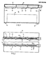
- the building room 10 shown in FIG. 1 can preferably be a textile machine room, but possibly also a room of another purpose, for example also an office or the like or another machine room or the like.
- this room 10 is a textile machine room in which textile machines 11 are located, for example ring spinning machines.
- supply air elements 13 On the underside of the ceiling 12 of this room 10, two mutually parallel rows of supply air elements 13, which adjoin one another without gaps, are arranged in the exemplary embodiment and form a supply air outlet system.
- the supply air elements 13 may be the same, but may also vary in their dimensions, preferably also in their lengths.
- Each row 14 of such supply air elements 13 extends approximately from one side wall 15 to the opposite side wall 16 of the room 10.
- the two rows 14 are spaced apart from one another in such a way that from the supply air elements 13 in one row 14 in the direction of the other row 14 blown out side streams 34, 35 (FIG.
- the individual supply air element 13 has a horizontal, straight, elongated duct section 17 of rectangular cross section, which is connected to adjacent duct sections 17 or a supply air supply duct 18 by means of flanges arranged on its two longitudinal ends.
- the most downstream channel pieces are closed at the downstream ends by closure plates.
- the channel pieces 17 of a row 14 form a continuous air channel is connected to the feed channel 18 supplying him with air.
- the supply air can preferably have a lower temperature, that is, lower temperatures than room temperature. However, if necessary, the supply air and uncooled air or can be e Ubertemp have temperature on the air, if the room to be heated 10th
- the exhaust air outlets 19 of the room are located on the floor.
- exhaust air outlets can also be arranged on the textile machines, for example in the form of thread suction tubes.
- This supply air outlet system having the two rows 14 prevents the occurrence of fiber fly in the supply air streams to a disruptive extent by completely or substantially preventing the rise of fiber flight arising on the machines 11 up to the ceiling, so that the feed air flows are practically not loaded with fiber fly and the fiber fly is thus essentially rapidly discharged from the room through the exhaust air and is not blown back to the machines with the supply air flows.
- this supply air outlet system can be expediently designed so that in the installation area of the machines only very small vertical upward air flows of a maximum of 0.3 to 0.4 m / s and vertical downward speeds of max. 0.3 - 0.6 m / s occur. If, on the other hand, the supply air carried fiber flight to the machines 11 to a considerable extent, it could cause faults, such as thread breaks or a reduction in the thread quality or Cause quality of other textile goods.
- the supply air outlet system can always be designed in such a way that the requirements for permissible air movements in the installation area of the machines that occur in textile machine halls can be met, especially in the case of processing sensitive goods, even with large air exchange rates as are required in textile machine halls.
- the duct section 17 of the individual supply air element 13 has a constant, rectangular cross section over its length and in its flat bottom there is a rectangular, elongated supply air outlet 20 which extends almost over the length of this duct section 17 and is therefore slit-shaped.
- This supply air outlet 2o is provided with a conventional rectifier 21 extending over its length and width, which consists of a plurality of mutually parallel profile elbows 21, which are designed as shown and with their upper horizontal legs 22 from the vertical legs in the downstream direction point.
- Each such angle piece 21 extends horizontally and perpendicular to the longitudinal direction of the duct piece 17 across the width of the supply air outlet 20.
- the rectifier 21 deflects supply air approximately vertically downward from the supply air flow flowing through this channel piece, which thus flows approximately vertically downwards through this supply air outlet 20, flow velocities of this vertical supply air flow downstream of the supply air outlet 20 of approximately 2-4 m / s preferably being provided can.
- the length of the supply air outlet 20 is much greater than its width. The length can advantageously be several meters. Its width can be, for example, 15 to 30 cm or even more or less.
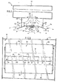
- This guide element 23 has a slot-shaped inlet air passage 26 which extends wholly or substantially over its length and thus wholly or substantially over the length of the inlet air outlet 20 located vertically above it, and which has baffles 24, 25 directed obliquely downwards on its two longitudinal sides Deflection members that strive at intervals from each other in the longitudinal direction of the supply air passage 26 alternately obliquely downwards and downwards to the left at angles of, for example, 15 to 35 °, here of approximately 24 °, as shown.
- the flap-shaped flat baffles 24 pointing downward to the right are arranged on the left long side and the baffle plates 25 pointing downward to the left on the right long side of the horizontal flat slot 27 of the supply air passage 26.
- the baffles 24, 25 By arranging the baffles 24, 25 in the longitudinal direction of the guide element 23, as shown, separated from one another by large gaps 28, these gaps 28 serve to blow down approximately vertical supply air blowing jets 29 downwards.
- the baffles 24 bring about supply air blowing jets 30 directed obliquely to the right in relation to FIG. 3, and the baffles 25 cause supply air blowing jets 31 flowing out obliquely to the left below Guide element 23 blown one behind the other.
- baffles 24, 25 can preferably be such that the blowing jets 30, 31 directed by them are not subject to the Coanda effect, so that these jets 30, 31 flow into the room according to the directional direction through the associated baffles 24, 25.
- the width of the rectangular slot 27 is substantially smaller than the width of the supply air outlet 20 located vertically above it, the longitudinal centers of the supply air outlet 20 and the slot 27 lying in the same vertical longitudinal center plane of symmetry of the duct piece 17.
- the plane of symmetry is also a plane of symmetry for the guide element 23 with the exception of its baffles 24.
- the individual supply air element 13 thus has a vertical longitudinal plane of symmetry which applies to all of its parts with the exception of the baffles.
- the distances between the two longitudinal outer edges 36 of the guide element 23 from the supply air passage 26 are substantially larger than the width of its slot 27.
- the guide element 23 has a horizontal, plate-shaped flat area 32, interrupted by the supply air passage 26, to which two closed, plate-shaped rectangular areas 33 adjoin, which are angled obliquely downwards - as shown - in this exemplary embodiment at angles of approximately 20 ° to the horizontal.
- the width of this guide element 23 is substantially larger than the width of the supply air outlet 20 arranged above it.
- the transverse center plane of the supply air element 13 can also be a plane of symmetry for it, with the exception of the rectifier 21.
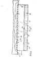
- 3 - 5 are drawn to scale after a supply air element examined in the experiment. This had the following dimensions. Length: preferably over a meter; the cross section of the channel piece 17 changes for pressure compensation; Width of the supply air outlet 20 approx. 20 cm; Width of the guide element 23 approx. 65 cm, width of the slot 27 approx. 10 cm and the horizontal plate sections adjoining it had widths of 9 cm each; the length of the baffles 24, 25 measured in the longitudinal direction of the guide element 23 was in each case approximately 28 cm, their widths approximately 10 cm; the length of the individual gap 28 measured in the longitudinal direction of the guide element 23 was approximately 7 cm; the distance of the guide element 23 from the supply air outlet 20 was approximately 18 cm.
- the supply air introduced into the individual row 14 of supply air elements 13 flows from the supply air outlets 20 toward the guide elements 23 at an approximately constant vertical downward speed of, for example, approximately 3 m / s.
- Each guide element 23 splits the incoming air flowing into them into two side streams 34, 35 and a central flow flowing into the incoming air passage 26, which is split into the blowing jets 29, 30, 31 by it.
- the two flat side streams 34, 35 which form very wide blowing jets, flow out along the inclined plate regions 33 of the guide element 23 over its longitudinal outer edges 36 at flow velocities of, for example, approximately 1.5-3 m / s.
- These suffer side streams 34, 35 are approximately symmetrical to each other and run transversely to the longitudinal direction of the? U air element 13.
- the blowing jets 30, 31 suck supply air by induction from the blast jets 29 and thereby slow down, so that their flow speed decreases relatively quickly and these jets 30, 31 are therefore very effectively sucked in by the side streams 34, 35 also by induction.
- the entire supply air is fanned out by the supply air elements 13.
- a very stable total room air flow is also achieved, which is therefore not adversely affected by warm air lift flows generated by the machines 11.
- the supply air passage 26 of the guide element 23 can also be divided into a plurality of individual openings, which result in approximately the same flow pattern.
- baffles 24, 25 shown other baffles can also be provided, which result in a similar splitting of the central flow or, if necessary, also another splitting into blowing jets.
- Other designs of the supply air outlet are also possible.
- the Blowing out a vertical jet and two slits on its two sides serve to blow out diverging jets, directed obliquely downwards towards the outside.
- the entire flow paths of the supply air downstream of the supply air outlet 20 of the individual supply air element 13 are grid-free in this preferred exemplary embodiment, that is to say they do not contain any air passage grilles, perforated plates or the like and / or room air to a considerable extent contain contamination by dust, fragments such as fibers or the like, etc.
- the supply air outlet system can, however, also be used in "clean rooms” and can then, if necessary, have wide-meshed air passage grilles for optical veneering, which do not or only slightly obstruct the air flows, and which are therefore essentially only provided for the optical effect.
- a supply air from the top downward duct can be provided, in the bottom of which there is a supply air outlet 20 with or without a rectifier.
- the new supply air outlet system also enables safe, precise dimensioning based on systematic measurements, i.e. easy adaptation to air volume, room geometry, local concentrated thermal loads and the like.
- At least one of the two side streams can also be subdivided into a plurality of blowing jets, preferably blown out parallel to one another, for example by vertical webs which carry the guide element on the longitudinal edges 36.
- the two side flows 34, 35 and the blowing jets 29, 30, 31 are blown out approximately perpendicular to the longitudinal direction of the guide element 23.
- the side flows or regions of the side flows 34, 35, as well as blowing jets blown out of the supply air passage 26, are inclined, preferably only slightly obliquely Can be blown out in the longitudinal direction of the guide element 23, which can be achieved by suitable steering or guide elements, for example by inclining at least one baffle plate 24 or 25.
- Supply air systems according to the invention are particularly suitable for rooms with room heights of approximately 2.30 m to 8 m and blow-out speeds which result in throw lengths of approximately 2 to 8 m for the side streams 34, 35.
- the air inlets 13 shown in the drawing are formed so that the supply air blown out of them results in an approximately symmetrical overall flow pattern in u Kunststoffiatas to the vertical longitudinal center plane of the Z. 13
- one or more previously known supply air outlet devices can, of course, also be provided in the room 10, for example on the ceiling, the side walls or at other suitable locations, in order to thereby ventilate and, if necessary, to temper the room areas caused by the supply air elements 13 air supply systems are deliberately not recorded and in which there is no risk of fiber flying.
Landscapes
- Engineering & Computer Science (AREA)
- Chemical & Material Sciences (AREA)
- Combustion & Propulsion (AREA)
- Mechanical Engineering (AREA)
- General Engineering & Computer Science (AREA)
- Duct Arrangements (AREA)
- Air-Flow Control Members (AREA)
- Ventilation (AREA)
- Compressor (AREA)
- Air-Conditioning For Vehicles (AREA)
- Self-Closing Valves And Venting Or Aerating Valves (AREA)
Priority Applications (1)
| Application Number | Priority Date | Filing Date | Title |
|---|---|---|---|
| AT86112960T ATE52610T1 (de) | 1985-09-23 | 1986-09-19 | Zuluftauslasssystem zur raumbelueftung. |
Applications Claiming Priority (2)
| Application Number | Priority Date | Filing Date | Title |
|---|---|---|---|
| DE3533833 | 1985-09-23 | ||
| DE3533833 | 1985-09-23 |
Publications (3)
| Publication Number | Publication Date |
|---|---|
| EP0216328A2 true EP0216328A2 (fr) | 1987-04-01 |
| EP0216328A3 EP0216328A3 (en) | 1987-11-19 |
| EP0216328B1 EP0216328B1 (fr) | 1990-05-09 |
Family
ID=6281669
Family Applications (1)
| Application Number | Title | Priority Date | Filing Date |
|---|---|---|---|
| EP86112960A Expired - Lifetime EP0216328B1 (fr) | 1985-09-23 | 1986-09-19 | Système de bouche de soufflage d'air pour la ventilation d'une pièce |
Country Status (3)
| Country | Link |
|---|---|
| EP (1) | EP0216328B1 (fr) |
| AT (1) | ATE52610T1 (fr) |
| DE (1) | DE3671099D1 (fr) |
Cited By (4)
| Publication number | Priority date | Publication date | Assignee | Title |
|---|---|---|---|---|
| CN107044683A (zh) * | 2017-03-29 | 2017-08-15 | 珠海格力电器股份有限公司 | 空调装置 |
| CN112503637A (zh) * | 2020-12-14 | 2021-03-16 | 中铁第四勘察设计院集团有限公司 | 一种适用于柱/壁的贴附射流末端送风装置及通风系统 |
| CN113566346A (zh) * | 2021-07-28 | 2021-10-29 | 同济大学 | 一种可调节的贴附射流送排风装置 |
| CN118579247A (zh) * | 2024-06-27 | 2024-09-03 | 上海外高桥造船有限公司 | 厨房送风散流器 |
Families Citing this family (1)
| Publication number | Priority date | Publication date | Assignee | Title |
|---|---|---|---|---|
| CN106642356B (zh) * | 2017-02-06 | 2022-07-19 | 广州华凌制冷设备有限公司 | 一种双出风口的壁挂式空调器 |
Family Cites Families (7)
| Publication number | Priority date | Publication date | Assignee | Title |
|---|---|---|---|---|
| US2407284A (en) * | 1942-06-20 | 1946-09-10 | Barber Colman Co | Air distribution outlet |
| US2432289A (en) * | 1943-09-08 | 1947-12-09 | William B Connor | Ventilating system |
| US2560802A (en) * | 1947-08-01 | 1951-07-17 | Air Factors | Laminar counterflow grille |
| GB686005A (en) * | 1949-12-01 | 1953-01-14 | Iain Maxwell Stewart | Air distributor device |
| FR1478372A (fr) * | 1965-12-06 | 1967-04-28 | Air Devices | Diffuseur mural |
| AT295804B (de) * | 1968-07-01 | 1972-01-25 | L T G Lufttechnische Ges Mit B | Luftaustrittseinrichtung für Klima- oder Lüftungsanlagen |
| DE2218794A1 (de) * | 1972-04-18 | 1973-10-31 | G Kiefer Gmbh Maschf | Verfahren und vorrichtung zum erzeugen eines keilfoermigen luftstrahls grosser breite |
-
1986
- 1986-09-19 AT AT86112960T patent/ATE52610T1/de not_active IP Right Cessation
- 1986-09-19 DE DE8686112960T patent/DE3671099D1/de not_active Expired - Lifetime
- 1986-09-19 EP EP86112960A patent/EP0216328B1/fr not_active Expired - Lifetime
Cited By (5)
| Publication number | Priority date | Publication date | Assignee | Title |
|---|---|---|---|---|
| CN107044683A (zh) * | 2017-03-29 | 2017-08-15 | 珠海格力电器股份有限公司 | 空调装置 |
| CN107044683B (zh) * | 2017-03-29 | 2023-06-30 | 珠海格力电器股份有限公司 | 空调装置 |
| CN112503637A (zh) * | 2020-12-14 | 2021-03-16 | 中铁第四勘察设计院集团有限公司 | 一种适用于柱/壁的贴附射流末端送风装置及通风系统 |
| CN113566346A (zh) * | 2021-07-28 | 2021-10-29 | 同济大学 | 一种可调节的贴附射流送排风装置 |
| CN118579247A (zh) * | 2024-06-27 | 2024-09-03 | 上海外高桥造船有限公司 | 厨房送风散流器 |
Also Published As
| Publication number | Publication date |
|---|---|
| EP0216328A3 (en) | 1987-11-19 |
| EP0216328B1 (fr) | 1990-05-09 |
| ATE52610T1 (de) | 1990-05-15 |
| DE3671099D1 (de) | 1990-06-13 |
Similar Documents
| Publication | Publication Date | Title |
|---|---|---|
| EP0192169B1 (fr) | Dispositif de guidage sans contact de bandes de matériau, en particulier de métal, au moyen d'un gaz | |
| EP0649821A1 (fr) | Dispositif pour l'échauffement ou le refroidissement de feuilles ou de rubans de verre | |
| DE69815867T2 (de) | Schwebetrocknereinheit | |
| EP0040693B1 (fr) | Procédé et installation pour la fabrication de nattes de fibres | |
| EP3327366B1 (fr) | Sortie d'air permettant le reglage de la temperature d'une chambre | |
| EP0216328B1 (fr) | Système de bouche de soufflage d'air pour la ventilation d'une pièce | |
| DE1154252B (de) | Abschirmung von Raumoeffnungen durch einen Luftschleier | |
| DE19804184A1 (de) | Vorrichtung zur schwebenden Führung von Bändern | |
| DE2328186A1 (de) | Einrichtung zum kuehlen und/oder erwaermen von raeumen | |
| DE2033195C3 (de) | Luftaustrittseinrichtung für Klimaanlagen | |
| DE3631967A1 (de) | Zuluftauslasssystem und verfahren zur raumbelueftung | |
| DE2138539A1 (de) | Verfahren und einrichtung zum einblasen von luft in einen raum | |
| DE3872532T2 (de) | Verfahren und luftverteilungsmittel zum zufuehren von luft in einen raumbereich. | |
| EP0663571A2 (fr) | Dispositif de refroidissement par convection | |
| EP3587943B1 (fr) | Dispositif d'aération et de mise en température d'une pièce dans un bâtiment | |
| DE4305471C1 (de) | Deckenluftauslaß, insbesondere Luftauslaßschiene | |
| DE2536840C2 (fr) | ||
| DE9309677U1 (de) | Luftaustritt für Belüftungsanlagen | |
| AT207088B (de) | Abschirmung von Raumöffnungen durch einen Luftschleier | |
| DE3242918C2 (fr) | ||
| EP0924474B1 (fr) | Sortie d'air pour une installation de ventilation | |
| EP4224077B1 (fr) | Passage d'air | |
| DE102012107542A1 (de) | Vorrichtung zur Aufteilung eines Luftstroms sowie damit ausgestattete Trocknungsanlage | |
| DE4107634A1 (de) | Geblaeseanlage zur windstreuung von spaenen | |
| DE1153872B (de) | Luftauslass fuer Luftkanaele |
Legal Events
| Date | Code | Title | Description |
|---|---|---|---|
| PUAI | Public reference made under article 153(3) epc to a published international application that has entered the european phase |
Free format text: ORIGINAL CODE: 0009012 |
|
| AK | Designated contracting states |
Kind code of ref document: A2 Designated state(s): AT CH DE FR GB IT LI SE |
|
| PUAL | Search report despatched |
Free format text: ORIGINAL CODE: 0009013 |
|
| AK | Designated contracting states |
Kind code of ref document: A3 Designated state(s): AT CH DE FR GB IT LI SE |
|
| 17P | Request for examination filed |
Effective date: 19880226 |
|
| 17Q | First examination report despatched |
Effective date: 19880722 |
|
| GRAA | (expected) grant |
Free format text: ORIGINAL CODE: 0009210 |
|
| AK | Designated contracting states |
Kind code of ref document: B1 Designated state(s): AT CH DE FR GB IT LI SE |
|
| REF | Corresponds to: |
Ref document number: 52610 Country of ref document: AT Date of ref document: 19900515 Kind code of ref document: T |
|
| REF | Corresponds to: |
Ref document number: 3671099 Country of ref document: DE Date of ref document: 19900613 |
|
| GBT | Gb: translation of ep patent filed (gb section 77(6)(a)/1977) | ||
| ITF | It: translation for a ep patent filed | ||
| PGFP | Annual fee paid to national office [announced via postgrant information from national office to epo] |
Ref country code: SE Payment date: 19900801 Year of fee payment: 5 |
|
| PGFP | Annual fee paid to national office [announced via postgrant information from national office to epo] |
Ref country code: FR Payment date: 19900810 Year of fee payment: 5 |
|
| PGFP | Annual fee paid to national office [announced via postgrant information from national office to epo] |
Ref country code: DE Payment date: 19900829 Year of fee payment: 5 |
|
| PGFP | Annual fee paid to national office [announced via postgrant information from national office to epo] |
Ref country code: GB Payment date: 19900831 Year of fee payment: 5 |
|
| ET | Fr: translation filed | ||
| PGFP | Annual fee paid to national office [announced via postgrant information from national office to epo] |
Ref country code: AT Payment date: 19900925 Year of fee payment: 5 |
|
| PGFP | Annual fee paid to national office [announced via postgrant information from national office to epo] |
Ref country code: CH Payment date: 19900928 Year of fee payment: 5 |
|
| ITTA | It: last paid annual fee | ||
| PLBE | No opposition filed within time limit |
Free format text: ORIGINAL CODE: 0009261 |
|
| STAA | Information on the status of an ep patent application or granted ep patent |
Free format text: STATUS: NO OPPOSITION FILED WITHIN TIME LIMIT |
|
| 26N | No opposition filed | ||
| PG25 | Lapsed in a contracting state [announced via postgrant information from national office to epo] |
Ref country code: GB Effective date: 19910919 Ref country code: AT Effective date: 19910919 |
|
| PG25 | Lapsed in a contracting state [announced via postgrant information from national office to epo] |
Ref country code: SE Effective date: 19910920 |
|
| PG25 | Lapsed in a contracting state [announced via postgrant information from national office to epo] |
Ref country code: LI Effective date: 19910930 Ref country code: CH Effective date: 19910930 |
|
| GBPC | Gb: european patent ceased through non-payment of renewal fee | ||
| PG25 | Lapsed in a contracting state [announced via postgrant information from national office to epo] |
Ref country code: FR Effective date: 19920529 |
|
| REG | Reference to a national code |
Ref country code: CH Ref legal event code: PL |
|
| PG25 | Lapsed in a contracting state [announced via postgrant information from national office to epo] |
Ref country code: DE Effective date: 19920602 |
|
| REG | Reference to a national code |
Ref country code: FR Ref legal event code: ST |
|
| EUG | Se: european patent has lapsed |
Ref document number: 86112960.9 Effective date: 19920408 |
|
| PG25 | Lapsed in a contracting state [announced via postgrant information from national office to epo] |
Ref country code: IT Free format text: LAPSE BECAUSE OF NON-PAYMENT OF DUE FEES;WARNING: LAPSES OF ITALIAN PATENTS WITH EFFECTIVE DATE BEFORE 2007 MAY HAVE OCCURRED AT ANY TIME BEFORE 2007. THE CORRECT EFFECTIVE DATE MAY BE DIFFERENT FROM THE ONE RECORDED. Effective date: 20050919 |