EP4224077B1 - Passage d'air - Google Patents
Passage d'air Download PDFInfo
- Publication number
- EP4224077B1 EP4224077B1 EP23154652.4A EP23154652A EP4224077B1 EP 4224077 B1 EP4224077 B1 EP 4224077B1 EP 23154652 A EP23154652 A EP 23154652A EP 4224077 B1 EP4224077 B1 EP 4224077B1
- Authority
- EP
- European Patent Office
- Prior art keywords
- air
- air outlet
- air guiding
- outlet surface
- air guide
- Prior art date
- Legal status (The legal status is an assumption and is not a legal conclusion. Google has not performed a legal analysis and makes no representation as to the accuracy of the status listed.)
- Active
Links
Images


Classifications
-
- F—MECHANICAL ENGINEERING; LIGHTING; HEATING; WEAPONS; BLASTING
- F24—HEATING; RANGES; VENTILATING
- F24F—AIR-CONDITIONING; AIR-HUMIDIFICATION; VENTILATION; USE OF AIR CURRENTS FOR SCREENING
- F24F13/00—Details common to, or for air-conditioning, air-humidification, ventilation or use of air currents for screening
- F24F13/02—Ducting arrangements
- F24F13/06—Outlets for directing or distributing air into rooms or spaces, e.g. ceiling air diffuser
-
- F—MECHANICAL ENGINEERING; LIGHTING; HEATING; WEAPONS; BLASTING
- F24—HEATING; RANGES; VENTILATING
- F24F—AIR-CONDITIONING; AIR-HUMIDIFICATION; VENTILATION; USE OF AIR CURRENTS FOR SCREENING
- F24F7/00—Ventilation
- F24F7/04—Ventilation with ducting systems, e.g. by double walls; with natural circulation
Definitions
- the present invention relates to an air outlet, namely a ceiling or wall outlet, according to claim 1
- the air vent comprises an interior space enclosed by a housing.
- An air connection nozzle and an air outlet surface formed by perforations are arranged on the housing, the perforations being located in a cladding panel.
- several air guide elements are arranged in front of the air outlet surface as viewed in the direction of flow.
- the respective air guide elements are inclined relative to the air outlet surface.
- the cladding panel can be part of the air vent or belong to a ceiling or wall construction, in particular a suspended ceiling or a curtain wall. In this case, which can be described as the most typical application, the air vent itself is arranged in a space between the cladding panel and a structural ceiling or wall.
- supply air is introduced into the interior space enclosed by the housing via the air connection nozzle.
- the supply air enters the room to be ventilated from the interior space via the air outlet surface.
- the air outlet surface is formed by perforations, with the perforations located in the cladding panel.
- the cladding panel can, for example, be a ceiling panel, such as a grid ceiling, or wall cladding.
- the housing of the air diffuser can also be designed without any further wall, with the perforations then being located, for example, in a panel of a grid ceiling or wall cladding.
- the air diffuser does not have any perforations before it is mounted in a panel or on a wall cladding, but initially has a free outlet cross-section for the air.
- the air diffuser only has the perforations after the housing has been placed on the cladding panel, i.e. a corresponding perforated sheet (of a grid ceiling or wall cladding).
- the air guiding elements are arranged in front of the air outlet surface, viewed in a flow direction. This means that the air guiding elements extend into the interior space enclosed by the housing.
- the flow direction is understood to be the direction in which the air, starting from the Air connection nozzle flows through the interior into the room to be ventilated, whereby the direction can change.
- air outlets are already known from the prior art and are used to introduce fresh air into a room.
- the air outlets known from the prior art usually have a ceiling panel arranged at the air outlet surface or are mounted on such a panel from above.
- Various air guide elements can be used to create an outflow from the air outlet surface parallel to the ceiling.
- the German patent application DE 10 2014 109 927 A1 Describes an air vent with at least three air guide elements, each of which is arranged adjacent to one another.
- the air guide elements are arranged in a circle around an axis and thus encircle a center point.
- Each air guide element overlaps the adjacent air guide element, forming an air guide channel between the adjacent air guide elements.
- the circularly arranged air guide elements create a jet deflection, i.e., a redirection of the supply air flow.
- a disadvantage of the devices known so far is the large overall width of the air outlets, which results from the need for a predetermined inflow zone.
- a floor panel is known that is designed like a casing and comprises a lower panel and an upper panel.
- the upper panel which may have a ceiling covering, has a plurality of air passages arranged in parallel rows, each with an elongated hole.
- the lower panel also has air passages covered by air guide hoods. In this way, the air leaving the upper panel upwards is imparted a different horizontal flow component depending on the row of air guide hoods, although the outflow still remains quite steeply upwards.
- the DE 22 25 455 B2 An air outlet with a duct-like housing and a slot-like air outlet surface.
- a guide element is arranged inside the housing, which can be used to influence the outflow of the supply air.
- the slot-like air outlet surface has recesses, so that the longitudinal edges of the air outlet surface are tooth-like.
- the guide element also has tooth-like edges, allowing for various settings for different airflow patterns.
- the object of the present invention is to further develop the air vents known from the prior art in such a way that the design is further optimized, whereby the air vents can be made slimmer and their manufacture is simplified. Furthermore, the aim is to achieve an air flow as parallel as possible to the cladding panel.
- the air passage according to the invention is characterized in that the air guiding elements are arranged one behind the other in the form of a row, wherein at least one air guiding element is inclined in a first direction relative to the air outlet surface and at least a second air guiding element is inclined in a direction opposite to the first direction. set second direction is inclined relative to the air outlet surface, whereby - viewed in a direction perpendicular to the air outlet surface - the air flowing through the air outlet is discharged in directions 180 degrees +/- 5 degrees opposite. In this way, the air leaving the air outlet from the first and second air guide elements is blown out into the room in opposite directions, with the two directions being rotated by 180 degrees +/- 5 degrees.
- the air guiding elements are arranged mirror-symmetrically to one another with respect to a vertically aligned central plane of the housing running parallel to a longitudinal direction of the air outlet.
- the air outlet according to the invention has at least two air guide elements, wherein the number of air guide elements can be adapted to a desired length of the air outlet.
- the air outlet according to the invention has four or more air guide elements.
- the air outlet it is conceivable for the air outlet to have, for example, four, six, eight, ten, or any other number of air guide elements. It is also conceivable for it to have an odd number of air guide elements.
- the respective air guide element is inclined relative to the air outlet surface in the direction of the interior of the air outlet and not into the space to be ventilated.
- a vertex of an acute angle of inclination, which the at least one air guide element forms with the air outlet surface, is preferably arranged in one region, i.e., near an elongated side wall of the housing.
- a vertex of an acute angle of inclination of the at least one second air guide element is preferably arranged correspondingly in one region, i.e., near an opposite, elongated side wall of the housing. This means that - viewed in the cross-section of the air outlet - a distance between the respective air guide element and the air outlet surface is smaller at a side wall than in a central region of the air outlet.
- the advantage of the air outlet according to the invention is that an air flow can escape from the air outlet over large areas of the air outlet surface in the direction of two opposite, preferably elongated side walls, preferably at least substantially parallel to the ceiling.
- the total width of the The air outlet can thus be reduced compared to the devices known from the prior art.
- two adjacent air outlets, each of which causes the supply air to flow out in opposite directions can be dispensed with, since the air outlet according to the invention already achieves an outflow of the supply air in two directions. Consequently, the air outlet according to the invention can achieve an outflow of the supply air in two directions, even though the air outlet is narrow in contrast to the air outlets known from the prior art.
- the air vent according to the invention can preferably have a width between 5 cm and 50 cm, more preferably between 10 cm and 30 cm.
- the height of the air vent according to the invention depends on the desired air volume and can preferably be between 10 cm and 50 cm.
- the length of the air vent according to the invention can be customized to individual requirements.
- a length of the respective air guide element measured transversely to a longitudinal axis of the air outlet is preferably at least approximately 50%, more preferably at least 70%, more preferably at least 80%, of the width of the air outlet.
- the respective air guide elements preferably have a width running parallel to the longitudinal axis of the air outlet of between 30% and 200% of the width of the air outlet.
- At least two air guiding elements arranged one behind the other are inclined in the same direction relative to the air outlet surface and at least two air guiding elements following in the row are inclined in the second direction relative to the air outlet surface.
- adjacent air guide elements may be inclined alternately in the first and second directions, or in the same direction over a certain distance along a longitudinal axis of the air outlet. It would also be conceivable for adjacent air guide elements to have different widths, so that the same outflow direction can be achieved over larger or smaller distances, depending on the circumstances. It is clear that the orientation of the air guide elements can be individually selected and planned.
- the invention provides that a plurality of preferably all air guide elements, inclined in the first direction and/or in the second direction, are each formed jointly by a strip-shaped, sawtooth-shaped component, preferably made of a sheet metal or plate, which preferably interlock in a comb-like manner.
- the respective sawtooth-shaped component preferably forms a type of tooth comb, wherein the respective air guide elements, which are inclined in the same direction, together form a tooth comb.
- Two components can preferably be separated from a sheet metal or plate by splitting the sheet metal or plate in a sawtooth shape, for example in the middle.
- a first part of the split sheet metal or plate preferably has a plurality of air guide elements spaced apart from one another and inclined in the same direction to the air outlet surface.
- a second part of the split sheet metal or plate preferably also forms a plurality of air guide elements spaced apart from one another, inclined in the same direction to the air outlet surface, but in the opposite direction to the air guide elements of the first part.
- the air guiding elements of the first part engage in the gaps, i.e., in areas of the second part where no air guiding elements are arranged.
- the air guiding elements of the first part are inclined in the first direction relative to the air outlet surface, and the air guiding elements of the second part are inclined in a second direction opposite to the first direction relative to the air outlet surface.
- the respective separated components can have a square, rectangular, rhombus-shaped, trapezoidal, or sinusoidal separating line.
- the separating line forms a cutting edge, e.g., of a punching tool, at which the components are separated from one another.
- At least one, preferably all, air guiding element or air guiding elements inclined in the first direction are movable relative to at least one, preferably all, air guiding element or air guiding elements inclined in the second direction, preferably in one direction perpendicular to the direction of the row of air guide elements and/or parallel to the air outlet surface. Due to the mobility of the air guide element or elements in a direction perpendicular to the direction of the row of air guide elements, the distance between two air guide elements with opposite inclinations can be changed in a direction perpendicular to the longitudinal axis of an air outlet.
- the air guide elements can therefore be nested more or less inside each other. This allows the flow behavior to be adapted depending on the application. For example, the air outlet surface through which the air flows can be enlarged or reduced. Likewise, a shift in a direction parallel to the air outlet surface can be advantageous, as this also allows the flow behavior to be adapted depending on the application.
- an angle of inclination of at least one air guide element, preferably all air guide elements, relative to the air outlet surface is formed by a plane spanned by the respective air guide element and the air outlet surface.
- the acute angle of inclination preferably points toward a side wall, preferably the elongated side wall, of the air outlet.
- the angle of inclination of at least one air guide element is adjustable relative to the air outlet surface.
- the position of the air guide elements can be adapted to the respective application.
- An advantageous further development of the invention provides for the housing to be detachable from the air outlet surface formed by a perforated ceiling panel.
- a detachable ceiling panel offers the advantage that the air guide elements can be subsequently modified, replaced, or repaired while the ceiling air outlet is installed.
- the ceiling panel also provides a visual barrier.
- An advantageous embodiment of the invention provides that two air guide elements aligned in the same direction are connected to each other by means of a web.
- a web between two air guide elements aligned in the same direction simplifies handling during assembly of the air outlet.
- the air guide elements, inclined in one direction, with their webs, thus resemble a comb with a long A web and teeth extending from it.
- Manufacturing is also particularly easy, especially when cutting a sawtooth-shaped component from a sheet or panel, if a strip is arranged between the two air guide elements. This eliminates the need to separate the air guide elements.
- the air outlet area can be reduced in relation to the perforated ceiling panel, at least in the edge areas. This improves the flow behavior.
- At least one air guide element preferably all air guide elements, has or have a bending axis arranged perpendicular to a longitudinal axis of the air outlet, wherein the respective air guide element can be bent or folded along this bending axis in the direction of the air outlet surface.
- the bendability or folding of the respective air guide element allows the outflow of the supply air from the air outlet to be modified.
- a particular air guide element it would be conceivable for a particular air guide element to have a flat, curved, beveled, or flat cross-section.
- the appropriate air guide element can be selected depending on the desired airflow pattern.
- a further embodiment of the invention provides that adjacent air guide elements abut one another—viewed in the direction of the row of air guide elements.
- the air flow can thus be precisely divided and discharged in the two intended directions.
- a wall is arranged at least between two adjacent air guide elements, preferably oriented in different directions.
- a wall is located between all adjacent air guide elements. This can improve the flow behavior of the supply air from the air outlet. Vortex flows in the immediately adjacent areas of two air guide elements oriented in different directions can be avoided with the help of the walls and the resulting spatial separation of the air guide elements.
- a further alternative development of the air passage according to the invention provides that at least one air guiding element has a slot on at least one side which is arranged adjacent to another air guiding element, wherein the slot preferably allows a displacement of the air guide element in a direction parallel to the direction of the row of air guide elements, so that preferably two adjacent air guide elements can be pushed into one another at least partially.
- a displacement of the air guide elements in the direction of the longitudinal axis of the air passage, so that two adjacent air guide elements can be pushed into one another, is particularly feasible if at least one of two adjacent air guide elements has a slot.
- the respective slot is preferably arranged on one or both sides of the respective air guide element.
- a flow cross-section formed between an air guide element and the air outlet surface can be closed by means of a partition element, which is preferably oriented perpendicular to the air outlet surface and/or is movable in a direction perpendicular to the air outlet surface, such that a gusset space located between the relevant air guide element and the air outlet surface is separated from the supply air guided through the connection piece into the interior of the housing.
- a partition element which is preferably arranged directly on the air outlet surface, the rear part of the air outlet surface and the corresponding air guide element, viewed in the direction of flow, namely the gusset space, is closed off. The supply air is thus blown into the room in a vertical direction.
- the partition element opens and thus frees the flow cross-section through the interstices, resulting in an increasingly horizontal outflow.
- Cold supply air is then blown horizontally along the ceiling into the room and "trickles" slowly, i.e., at a low falling speed, into the room. This creates a pleasant, draft-free indoor climate.
- the at least one air guide element is an injection-molded element. Injection-molded elements can be manufactured very quickly and in large quantities. Furthermore, production costs can be reduced in this way.
- the cladding panel and the air guide elements form different components.
- the air outlet can be easily retrofitted into existing buildings.
- the air outlet is mounted on a regularly perforated ceiling cladding panel and arranged in a ceiling cavity.
- the air outlet can be arranged behind a wall cladding panel.
- the air guide elements extend directly to the cladding panel with their ends facing the cladding panel and/or contact the cladding panel with their ends facing the cladding panel from a side facing away from the room to be ventilated.
- the gap between the cladding panel and the ends of the air guide elements facing the cladding panel is reduced to almost zero. This optimizes the outflow of the supply air parallel to the wall or ceiling, since the Coanda effect can be optimally established due to the virtually “frictionless” and smooth transition between the air guide element and the cladding panel.
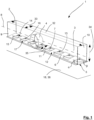
- the Figure 1 shows a first embodiment of an air outlet 1 according to the invention.
- a housing 2 encloses an interior space 3.
- An air connection piece 4 is arranged on the housing 2 , through which supply air is introduced horizontally into the interior space 3 of the air outlet 1.
- the supply air is redirected in a vertical direction to an air outlet surface 5 formed by perforations, the perforations not being shown in the figure.
- the air outlet surface 5 is arranged horizontally or, in an installed state of the air outlet 1 , parallel to a ceiling plane not shown here. In principle, however, the air outlet surface can also be in a wall and thus aligned vertically.
- the air outlet surface 5 is formed by a large-area cladding panel 36 in the form of a perforated ceiling panel 18 , which is detachably connected to the housing 2 and is shown only partially schematically here.
- This perforated ceiling panel 18 typically projects laterally considerably beyond the base area of the air outlet in all directions and which has the perforations. Accordingly, the air outlet 1 is placed on the ceiling plate 18 and uses its perforations to form the air outlet surface.
- the base area 17 of the housing 2 located at the air outlet surface 5 is thus significantly smaller than the total area of the perforated ceiling panel 18.
- several flat air guide elements 6, 7 are arranged in front of the air outlet surface 5.
- the air guide elements 6, 7 are each inclined relative to the air outlet surface 5 , with the respective air guide elements 6, 7 pointing into the interior space 3 .
- a plurality of air guide elements 6, 7 are arranged one behind the other along a longitudinal axis 8 of the air outlet 1.
- the air guide elements 6 are inclined in a first direction relative to the air outlet surface 5.
- An acute angle of inclination ⁇ between the air outlet surface 5 and the air guide element 6 or a plane spanned by the air guide element 6 is between 5 and 10 degrees, with the angle of inclination ⁇ pointing in the direction of a respective side wall 9, 10 of the air outlet 1.
- the adjacent air guide elements 7 are inclined in a second direction opposite to the first direction relative to the air outlet surface 5.
- An angle of inclination ⁇ between a plane spanned by the air guide element 7 and the air outlet surface 5 is between 5 and 10 degrees.
- any two adjacent air guide elements 6, 7 are thus alternately inclined in two different directions.
- the angles of inclination ⁇ and ⁇ can be different or equal.
- the adjacent air guide elements 6, 7 abut one another, viewed in one direction of the row of air guide elements or along the longitudinal axis 8 of the air outlet 9 .
- angles of inclination ⁇ and ⁇ of the corresponding air guiding elements 6, 7 are adjustable so that the air flow can be individually adapted to the respective environment and the operating conditions as well as the specific temperature control task.
- the respective air guide elements 6, 7 are in the Figure 1 arranged in such a way that the supply air is deflected in a substantially horizontal direction upon exiting the air outlet. This means that the supply air initially exits the air outlet surface 5 at an angle corresponding to the inclination of the air guide elements 6, 7 and then clings to the underside of a room ceiling, so that it flows horizontally along the room ceiling (Coanda effect). It can be seen that a wedge-shaped gap between the cladding panel 36 and the air guide elements 6, 7 on the side of the air guide elements 6, 7 facing away from the free end of the air guide elements 6, 7 always decreases to zero.
- the air guiding elements 6 which are each aligned in the same direction, are connected to each other by means of a web 11 , so that the air guide elements 6 , which are inclined in the same direction, together form a type of comb.
- all of the air guide elements 6 inclined in the first direction together form a strip-shaped, sawtooth-shaped component 12, which was cut from a single sheet of metal.
- the air guide elements 7 which are inclined in opposite directions, are also connected to one another by a web 13 and also form a strip-shaped, sawtooth-shaped component 14.
- both components 12, 14 are cut from a single sheet of metal.
- the webs 11, 13 close the air outlet surface 5 in edge areas 15, 16 so that outflow can be improved.
- the air outlet 1 has a length 32 measured parallel to the longitudinal axis 8 , a width 33 running horizontally and perpendicular to the longitudinal axis 8 , and a height 34 running vertically and perpendicular to the longitudinal axis 8.
- a length 35 of the air guide elements 6, 7 is approximately 90% of the width 33 of the air outlet 1. It is understood that the length 35 of the air guide elements 6, 7 can also have other values, such as 70%, 80%, 95% of the width 33 of the air outlet 1 or others.
- the air guiding elements not to be connected to each other via webs.
- the respective webs could, for example, also be arranged separately on the air outlet surface if necessary.
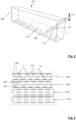
- the Figure 2 shows an alternative embodiment of an air passage 101 according to the invention.
- the air passage 101 according to the Figure 2 essentially corresponds to air outlet 1 according to Figure 1
- at least one row of air guide elements 106 inclined in the same direction has a slot 19 on one side 20.
- This slot 19 allows the air guide elements 106 to be displaced in a direction along the longitudinal axis 108 of the air outlet 101.
- At least one, preferably all, air guide elements are mounted for movement in a direction perpendicular to the longitudinal axis of the air passage or perpendicular to the direction of the row of air guide elements. It would also be conceivable for at least one air guide element, preferably all of the air guide elements, to be movable parallel to the air outlet surface.
- the Figure 3 shows four air outlets 101 arranged side by side according to Figure 2 from a bottom side. For better illustration, no perforated ceiling panels are shown.
- the air guide elements 106, 107 each inclined in the same direction, are connected to one another by means of webs 11, 13.
- two middle air outlets 101b, 101c two adjacent air guide elements 106, 107 , inclined in different directions, are shifted into one another, as is the case with the air outlet 101 according to Figure 2 is shown.
- the air guide elements 106, 107 which are inclined in different directions, are not pushed into one another.
- an embodiment of an air vent not shown here similar to the air vent according to Figure 1 , does not have continuous, flat air guide elements. Instead, the air guide elements each have a bending axis arranged perpendicular to a longitudinal axis of the air outlet. Along this bending axis, the guide elements can be bent toward the air outlet surface, creating a prism-like air guide plate.
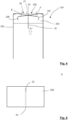
- the Figure 4 shows a cross section of a further alternative embodiment of an air passage 201, wherein the air passage 201 differs from the air passage 1 according to the Figure 1 differs in that the air guiding elements 206, 207 have a slot 22 arranged centrally, parallel to the longitudinal axis of the air passage 201 (not shown here). This means that at least one edge region 23 of the air guiding element 206, 207 is continuous.
- One of these air guiding elements 206 is shown in the Figure 5 , in which the slot 22 can be seen.
- the slot 22 is also located in a central region 24 in which the two air guide elements 206, 207, which are inclined in different directions, intersect.
- a partition element 25 is arranged in the slot 22.
- the partition element 25 is oriented perpendicular to the air outlet surface 205 and can be moved in a direction perpendicular to the air outlet surface 205. With the aid of the partition element 25 , a flow cross-section 26 formed between an air guide element 206, 207 and the air outlet surface 205 can be closed, so that a gusset space 27 located between the respective air guide element 206, 207 and the air outlet surface 205 cannot be flowed through by the supply air guided through the air connection piece into the interior 203 of the housing 202 .
- the partition element 25 can be moved from an open position, in which the partition element 25 releases the flow cross-section 26 , into a closed position by means of a thermal actuator (not shown here). In the closed position, the flow cross-section 26 is at least partially blocked.
- the closed position is Figure 4 shown.
- the partition element 25 is in its open position, so that the supply air leaves the housing 202 in a horizontal direction. If a room is sufficiently cold, the partition element 25 closes the flow cross-section 26, so that warm supply air is blown vertically into the room. Intermediate positions are of course also possible.
- the cladding panel 36 in the form of a ceiling panel 18 is in the Figure 4 not shown, but the air outlet surface 205 is illustrated. It is understood that the ceiling panel 18 runs in the plane of the air outlet surface 205 .
- the Figure 6 shows a further alternative embodiment of an air outlet 301.
- the air outlet 301 has a housing 302 and an air connection nozzle (not shown here) located on the housing 302.
- the housing 302 encloses an interior space 303.
- a horizontal air outlet surface 305 has perforations (not shown here).
- several air guide elements 306, 307 are arranged according to Figure 7
- the air guide elements 306 form an angle of inclination ⁇ of between 5 and 10 degrees with the air outlet surface 305.
- the air guide elements 307 form an angle of inclination ⁇ of between 5 and 10 degrees (not shown here) with the air outlet surface 305.
- the air guide elements 306, 307 are inserted into the housing 302 , whereby, depending on the application, the air guide elements 306, 307 can be inserted in different directions.
- Figure 6 shows that two adjacent air guide elements 306, 307 are inclined in opposite directions. This allows the supply air to flow into the room in two different directions.
- the air guide elements it would also be conceivable for the air guide elements to all point in the same direction, or for only the middle air guide elements to be oriented in an opposite direction. All possible orientations are conceivable using this embodiment.
- the Figure 7 shows one of the in the air passage 301 according to Figure 6 inserted air guide elements 306.
- the air guide element 306 is surrounded by a frame 28 , so that installation in the air passage 301 is simplified.
- the frame 28 forms a wall 29 between two adjacent air guide elements 306, 307 , so that the two air guide elements 306, 307 are fluidically separated from each other.
- the air guide element 306 is made in one piece with the frame 28 from an injection-molded element.
- the Figure 8 shows a type of cover 30 by means of which the air guide element 306 can be closed with its frame. Likewise, the cover 30 can be used in such a way that the flow direction can be changed.
Landscapes
- Engineering & Computer Science (AREA)
- Chemical & Material Sciences (AREA)
- Combustion & Propulsion (AREA)
- Mechanical Engineering (AREA)
- General Engineering & Computer Science (AREA)
- Air-Flow Control Members (AREA)
- Duct Arrangements (AREA)
Claims (15)
- Passage d'air, à savoir sortie (1, 101, 201, 301) en plafond ou murale, comprenant- un boîtier (2, 202, 302) entourant un espace intérieur (3, 203, 303), pourvu∘ d'une tubulure (4, 304) de prise d'air et∘ d'une surface (5, 205, 305) de sortie d'air, constituée de perforations, les perforations se trouvant dans une plaque d'habillage et- plusieurs éléments (6, 106, 206, 306, 7, 107, 207, 307) déflecteurs d'air placés dans l'espace intérieur (3, 203, 303), qui considérés dans une direction de circulation, sont placés à l'avant de la surface (5, 205, 305) de sortie d'air et dont chacun est incliné par rapport à la surface (5, 205, 305) de sortie d'air,les éléments (6, 106, 206, 306, 7, 107, 207, 307) déflecteurs d'air étant placés sous la forme d'une rangée, les uns derrière les autres, au moins un élément (6, 106, 206, 306, 7, 107, 207, 307) déflecteur d'air étant incliné dans une première direction par rapport à la surface (5, 205, 305) de sortie d'air et au moins un deuxième élément (6, 106, 206, 306, 7, 107, 207, 307) déflecteur d'air étant incliné dans une deuxième direction placée à l'opposée de la première direction, par rapport à la surface (5, 205, 305) de sortie d'air, suite à quoi (dans une première direction de visée à la perpendiculaire de la surface (5, 205, 305) de sortie d'air), il s'effectue un écoulement de l'air traversant le passage d'air (1, 101, 201, 301) dans des directions opposées de la valeur de 180 degrés +/- 5 degrés, caractérisé en ce que, par des extrémités faisant face à la plaque d'habillage, les éléments (6, 106, 206, 306, 7, 107, 207, 307) déflecteurs d'air s'étendent directement jusqu'à la plaque d'habillage et / ou par des extrémités faisant face à la plaque d'habillage, entrent en contact avec la plaque d'habillage à partir d'un côté opposé à la pièce qu'il s'agit de ventiler, tous les éléments (6, 106, 206) déflecteurs d'air inclinés dans la première direction et tous les éléments (7, 107, 207) déflecteurs d'air inclinés dans la deuxième direction étant constitués chaque fois conjointement d'un composant (12, 14) en forme de bande en dents de scie, qui s'engrène à la manière d'un peigne, des éléments (6, 106, 206) déflecteurs d'air inclinés dans la première direction s'engrenant dans des brèches entre des éléments (7, 107, 207) déflecteurs d'air inclinés dans la deuxième direction.
- Passage d'air (1, 101, 201, 301) selon la revendication 1, caractérisé en ce que parmi les éléments (6, 106, 206, 306, 7, 107, 207, 307) déflecteurs d'air placés dans une rangée, alternativement, les uns derrière les autres, chaque fois un élément (6, 106, 206, 306) déflecteur d'air est incliné dans la première direction et un élément (7, 107, 207, 307) déflecteur d'air est incliné dans la deuxième direction par rapport à la surface (5, 205, 305) de sortie d'air.
- Passage d'air (1, 101, 201) selon l'une quelconque des revendications précédentes, caractérisé en ce que le composant (12, 14) en forme de bande en dents de scie est conçu en tôle ou en une plaque.
- Passage d'air selon l'une quelconque des revendications précédentes, caractérisé en ce qu'au moins un élément déflecteur d'air incliné dans la première direction est mobile par rapport à au moins un élément déflecteur d'air incliné dans la deuxième direction, de préférence dans une direction perpendiculaire à la direction de la rangée des éléments déflecteurs d'air et / ou à la parallèle de la surface de sortie d'air.
- Passage d'air (1, 101, 201, 301) selon l'une quelconque des revendications précédentes, caractérisé en ce qu'un angle d'inclinaison (α, β) d'au moins un élément (6, 106, 206, 306) déflecteur d'air, de préférence de tous les éléments (6, 106, 206, 306, 7, 107, 207, 307) déflecteurs d'air par rapport à la surface (5, 205, 305) de sortie d'air se situe entre 3 degrés et 15 degrés, de préférence entre 5 degrés et 10 degrés.
- Passage d'air (1, 101, 201) selon l'une quelconque des revendications précédentes, caractérisé en ce qu'un angle d'inclinaison (α, β) d'au moins un élément (6, 106, 206, 306) déflecteur d'air, de préférence de tous les éléments (6, 106, 206, 306, 7, 107, 207, 307) déflecteurs d'air, par rapport à la surface (5, 205, 305) de sortie d'air est ajustable.
- Passage d'air (1, 101, 201, 301) selon l'une quelconque des revendications précédentes, caractérisé en ce que le boîtier (2, 202, 302) est amovible de la surface (5, 205, 305) de sortie d'air constituée par une plaque de plafond (18) perforée.
- Passage d'air (1, 101, 201) selon l'une quelconque des revendications précédentes, caractérisé en ce que deux éléments (6, 106, 206) déflecteurs d'air orientés dans la même direction sont assemblés l'un avec l'autre au moyen d'une barrette (11).
- Passage d'air selon l'une quelconque des revendications précédentes, caractérisé en ce qu'au moins un élément déflecteur d'air comporte un axe d'inflexion placé à la perpendiculaire d'un axe longitudinal du passage d'air, l'élément déflecteur d'air pouvant être infléchi ou chanfreiné le long dudit axe d'inflexion dans la direction de la surface de sortie d'air.
- Passage d'air (1, 101, 201) selon l'une quelconque des revendications précédentes, caractérisé en ce que des éléments (6, 106, 206, 7, 107, 207) déflecteurs d'air voisins (considérés dans la direction de la rangée des éléments (6, 106, 206, 7, 107, 207) déflecteurs d'air) sont aboutés.
- Passage d'air (301) selon l'une quelconque des revendications 1 à 9, caractérisé en ce qu'au moins entre deux éléments (306, 307) déflecteurs d'air voisins, orientés dans une direction différente est placée une paroi, de préférence entre chaque élément déflecteur d'air voisin est placée une paroi.
- Passage d'air (101) selon l'une quelconque des revendications 1 à 10, caractérisé en ce qu'au moins un élément (106) déflecteur d'air sur au moins un côté (20), qui est placé au voisinage d'un autre élément (107) déflecteur d'air, comporte une fente (19), la fente (19) permettant de préférence un déplacement de l'élément (106) déflecteur d'air dans la direction de l'axe longitudinal (108) du passage d'air (101), de sorte que de préférence deux éléments (106, 107) déflecteurs d'air voisins, orientés dans des directions différentes soient emboîtables au moins partiellement l'un dans l'autre.
- Passage d'air (201) selon l'une quelconque des revendications 1 à 11, caractérisé en ce qu'une section transversale (26) de circulation constituée entre un élément (206) déflecteur d'air et la surface (205) de sortie d'air peut se fermer au moyen d'un élément (25) de cloisonnement, qui est orienté de préférence à la perpendiculaire de la surface (205) de sortie d'air et / ou qui est mobile dans une direction à la perpendiculaire de la surface (205) de sortie d'air, de telle sorte qu'un espace formant gousset (27) se trouvant entre l'élément (206) déflecteur d'air concerné et la surface (205) de sortie d'air ne puisse pas être traversé par l'air entrant dirigé à travers la tubulure de raccordement dans l'espace intérieur du boîtier.
- Passage d'air selon la revendication 12, caractérisé en ce que l'élément (25) de cloisonnement est transférable au moyen d'un servomoteur de régulation, de préférence d'un servomoteur de régulation basé sur la dilatation thermique d'une cire, d'une position d'ouverture, dans laquelle l'élément (25) de cloisonnement libère la section transversale (26) de circulation, dans une position de fermeture, dans laquelle l'élément (25) de cloisonnement bloque au moins partiellement la section transversale de circulation.
- Passage d'air selon l'une quelconque des revendications précédentes, caractérisé en ce que l'au moins un élément (306, 307) déflecteur d'air est un élément moulé par injection.
Applications Claiming Priority (1)
| Application Number | Priority Date | Filing Date | Title |
|---|---|---|---|
| DE102022102497.0A DE102022102497A1 (de) | 2022-02-03 | 2022-02-03 | Luftdurchlass |
Publications (3)
| Publication Number | Publication Date |
|---|---|
| EP4224077A1 EP4224077A1 (fr) | 2023-08-09 |
| EP4224077C0 EP4224077C0 (fr) | 2025-04-02 |
| EP4224077B1 true EP4224077B1 (fr) | 2025-04-02 |
Family
ID=85173000
Family Applications (1)
| Application Number | Title | Priority Date | Filing Date |
|---|---|---|---|
| EP23154652.4A Active EP4224077B1 (fr) | 2022-02-03 | 2023-02-02 | Passage d'air |
Country Status (2)
| Country | Link |
|---|---|
| EP (1) | EP4224077B1 (fr) |
| DE (1) | DE102022102497A1 (fr) |
Family Cites Families (6)
| Publication number | Priority date | Publication date | Assignee | Title |
|---|---|---|---|---|
| DE2225455B2 (de) | 1972-05-23 | 1976-07-01 | Nordluft Gerätebau GmbH, 2057 Wentorf | Mit luft beschickbarer, in raumdekken oder -waenden angeordneter, schlitzfoermig ausgebildeter linearer luftauslass |
| DE7712701U1 (de) | 1977-04-22 | 1977-08-18 | Mero-Werke Kg Dr.-Ing. Max Mengeringhausen, 8700 Wuerzburg | Fussbodenplatte fuer doppelten fussboden mit luftdurchtrittsoeffnungen |
| GB8316716D0 (en) * | 1983-06-20 | 1983-07-20 | Waterloo Grille Co Ltd | Diffuser |
| DE202006007846U1 (de) | 2005-05-20 | 2006-08-03 | M+W Zander Gebäudetechnik GmbH | Luftauslass |
| DE102010001319A1 (de) | 2010-01-28 | 2011-08-18 | YIT Germany GmbH, 80992 | Luftdurchlass mit einem Gehäuse sowie ein Deckensegel mit Luftdurchlass |
| DE102014109927A1 (de) | 2014-07-15 | 2016-01-21 | Ltg Aktiengesellschaft | Luftleitanordnung für einen Deckenstrahlauslass und Verfahren |
-
2022
- 2022-02-03 DE DE102022102497.0A patent/DE102022102497A1/de active Pending
-
2023
- 2023-02-02 EP EP23154652.4A patent/EP4224077B1/fr active Active
Also Published As
| Publication number | Publication date |
|---|---|
| EP4224077C0 (fr) | 2025-04-02 |
| EP4224077A1 (fr) | 2023-08-09 |
| DE102022102497A1 (de) | 2023-08-03 |
Similar Documents
| Publication | Publication Date | Title |
|---|---|---|
| EP3063026A1 (fr) | Diffuseur d'air | |
| DE102009007037A1 (de) | Ausströmdüse einer Belüftungsvorrichtung oder Klimaanlage für Fahrzeuge | |
| DE2556538B2 (de) | Anordnung zum Belüften und/oder Temperieren eines Raumes | |
| DE2609030C3 (de) | Vorrichtung zum Führen von aus einer luftdurchlässigen perforierten Fläche austretenden Luftströmen | |
| EP0267486B1 (fr) | Dispositif pour diriger un courant d'air | |
| DE2933083C2 (de) | Luftauslaß für Klimaanlagen | |
| EP2288855B1 (fr) | Sortie d'air | |
| EP2141429B1 (fr) | Tour de refroidissement hybride | |
| EP2860467B1 (fr) | Sortie d'air | |
| EP2587179B1 (fr) | Bouche d'aération | |
| DE3111360C2 (de) | Lüftungsvorrichtung für Räume mit zwei getrennten Strömungswegen zur Be- und Entlüftung | |
| EP4224077A1 (fr) | Passage d'air | |
| DE19626884C2 (de) | Luftauslaß | |
| DE102007039306B4 (de) | Luftauslass | |
| EP3236173B1 (fr) | Procédé de climatisation d'une pièce | |
| EP0657014B1 (fr) | Sortie d'air pour installations de ventilation | |
| DE2536840C2 (fr) | ||
| DE2525977C2 (de) | Lüftungsgitter für die Belüftung von Innenräumen | |
| DE102008031219B3 (de) | Hybridkühlturm | |
| DE19912567A1 (de) | Luftleiteinrichtung für einen Luftdurchlaß | |
| EP4276378B1 (fr) | Passage d'air | |
| DE2828338C2 (de) | Rechteckiger Deckenauslaß | |
| DE19937573C1 (de) | Luftauslaß | |
| EP3803225B1 (fr) | Sortie d?air de refoulement | |
| EP3293463A1 (fr) | Diffuseur linéaire pour installation de cloisons d'aire |
Legal Events
| Date | Code | Title | Description |
|---|---|---|---|
| PUAI | Public reference made under article 153(3) epc to a published international application that has entered the european phase |
Free format text: ORIGINAL CODE: 0009012 |
|
| STAA | Information on the status of an ep patent application or granted ep patent |
Free format text: STATUS: THE APPLICATION HAS BEEN PUBLISHED |
|
| AK | Designated contracting states |
Kind code of ref document: A1 Designated state(s): AL AT BE BG CH CY CZ DE DK EE ES FI FR GB GR HR HU IE IS IT LI LT LU LV MC ME MK MT NL NO PL PT RO RS SE SI SK SM TR |
|
| STAA | Information on the status of an ep patent application or granted ep patent |
Free format text: STATUS: REQUEST FOR EXAMINATION WAS MADE |
|
| 17P | Request for examination filed |
Effective date: 20231121 |
|
| RBV | Designated contracting states (corrected) |
Designated state(s): AL AT BE BG CH CY CZ DE DK EE ES FI FR GB GR HR HU IE IS IT LI LT LU LV MC ME MK MT NL NO PL PT RO RS SE SI SK SM TR |
|
| GRAP | Despatch of communication of intention to grant a patent |
Free format text: ORIGINAL CODE: EPIDOSNIGR1 |
|
| STAA | Information on the status of an ep patent application or granted ep patent |
Free format text: STATUS: GRANT OF PATENT IS INTENDED |
|
| RIC1 | Information provided on ipc code assigned before grant |
Ipc: F24F 13/06 20060101ALI20241209BHEP Ipc: F24F 7/04 20060101AFI20241209BHEP |
|
| INTG | Intention to grant announced |
Effective date: 20250102 |
|
| GRAS | Grant fee paid |
Free format text: ORIGINAL CODE: EPIDOSNIGR3 |
|
| GRAA | (expected) grant |
Free format text: ORIGINAL CODE: 0009210 |
|
| STAA | Information on the status of an ep patent application or granted ep patent |
Free format text: STATUS: THE PATENT HAS BEEN GRANTED |
|
| AK | Designated contracting states |
Kind code of ref document: B1 Designated state(s): AL AT BE BG CH CY CZ DE DK EE ES FI FR GB GR HR HU IE IS IT LI LT LU LV MC ME MK MT NL NO PL PT RO RS SE SI SK SM TR |
|
| REG | Reference to a national code |
Ref country code: GB Ref legal event code: FG4D Free format text: NOT ENGLISH |
|
| REG | Reference to a national code |
Ref country code: CH Ref legal event code: EP |
|
| REG | Reference to a national code |
Ref country code: IE Ref legal event code: FG4D Free format text: LANGUAGE OF EP DOCUMENT: GERMAN |
|
| REG | Reference to a national code |
Ref country code: DE Ref legal event code: R096 Ref document number: 502023000741 Country of ref document: DE |
|
| U01 | Request for unitary effect filed |
Effective date: 20250414 |
|
| U07 | Unitary effect registered |
Designated state(s): AT BE BG DE DK EE FI FR IT LT LU LV MT NL PT RO SE SI Effective date: 20250422 |
|
| PG25 | Lapsed in a contracting state [announced via postgrant information from national office to epo] |
Ref country code: ES Free format text: LAPSE BECAUSE OF FAILURE TO SUBMIT A TRANSLATION OF THE DESCRIPTION OR TO PAY THE FEE WITHIN THE PRESCRIBED TIME-LIMIT Effective date: 20250402 |
|
| PG25 | Lapsed in a contracting state [announced via postgrant information from national office to epo] |
Ref country code: GR Free format text: LAPSE BECAUSE OF FAILURE TO SUBMIT A TRANSLATION OF THE DESCRIPTION OR TO PAY THE FEE WITHIN THE PRESCRIBED TIME-LIMIT Effective date: 20250703 Ref country code: NO Free format text: LAPSE BECAUSE OF FAILURE TO SUBMIT A TRANSLATION OF THE DESCRIPTION OR TO PAY THE FEE WITHIN THE PRESCRIBED TIME-LIMIT Effective date: 20250702 |
|
| PG25 | Lapsed in a contracting state [announced via postgrant information from national office to epo] |
Ref country code: PL Free format text: LAPSE BECAUSE OF FAILURE TO SUBMIT A TRANSLATION OF THE DESCRIPTION OR TO PAY THE FEE WITHIN THE PRESCRIBED TIME-LIMIT Effective date: 20250402 |
|
| PG25 | Lapsed in a contracting state [announced via postgrant information from national office to epo] |
Ref country code: HR Free format text: LAPSE BECAUSE OF FAILURE TO SUBMIT A TRANSLATION OF THE DESCRIPTION OR TO PAY THE FEE WITHIN THE PRESCRIBED TIME-LIMIT Effective date: 20250402 |
|
| PG25 | Lapsed in a contracting state [announced via postgrant information from national office to epo] |
Ref country code: RS Free format text: LAPSE BECAUSE OF FAILURE TO SUBMIT A TRANSLATION OF THE DESCRIPTION OR TO PAY THE FEE WITHIN THE PRESCRIBED TIME-LIMIT Effective date: 20250702 |
|
| PG25 | Lapsed in a contracting state [announced via postgrant information from national office to epo] |
Ref country code: IS Free format text: LAPSE BECAUSE OF FAILURE TO SUBMIT A TRANSLATION OF THE DESCRIPTION OR TO PAY THE FEE WITHIN THE PRESCRIBED TIME-LIMIT Effective date: 20250802 |
|
| PG25 | Lapsed in a contracting state [announced via postgrant information from national office to epo] |
Ref country code: SM Free format text: LAPSE BECAUSE OF FAILURE TO SUBMIT A TRANSLATION OF THE DESCRIPTION OR TO PAY THE FEE WITHIN THE PRESCRIBED TIME-LIMIT Effective date: 20250402 |
|
| PG25 | Lapsed in a contracting state [announced via postgrant information from national office to epo] |
Ref country code: CZ Free format text: LAPSE BECAUSE OF FAILURE TO SUBMIT A TRANSLATION OF THE DESCRIPTION OR TO PAY THE FEE WITHIN THE PRESCRIBED TIME-LIMIT Effective date: 20250402 |
|
| PG25 | Lapsed in a contracting state [announced via postgrant information from national office to epo] |
Ref country code: SK Free format text: LAPSE BECAUSE OF FAILURE TO SUBMIT A TRANSLATION OF THE DESCRIPTION OR TO PAY THE FEE WITHIN THE PRESCRIBED TIME-LIMIT Effective date: 20250402 |
|
| U20 | Renewal fee for the european patent with unitary effect paid |
Year of fee payment: 4 Effective date: 20251230 |
|
| PLBE | No opposition filed within time limit |
Free format text: ORIGINAL CODE: 0009261 |
|
| STAA | Information on the status of an ep patent application or granted ep patent |
Free format text: STATUS: NO OPPOSITION FILED WITHIN TIME LIMIT |
|
| REG | Reference to a national code |
Ref country code: CH Ref legal event code: L10 Free format text: ST27 STATUS EVENT CODE: U-0-0-L10-L00 (AS PROVIDED BY THE NATIONAL OFFICE) Effective date: 20260211 |
|
| REG | Reference to a national code |
Ref country code: CH Ref legal event code: U11 Free format text: ST27 STATUS EVENT CODE: U-0-0-U10-U11 (AS PROVIDED BY THE NATIONAL OFFICE) Effective date: 20260301 |
|
| 26N | No opposition filed |
Effective date: 20260105 |
|
| PGFP | Annual fee paid to national office [announced via postgrant information from national office to epo] |
Ref country code: CH Payment date: 20260301 Year of fee payment: 4 |