EP0216356A2 - Anlagen-Diagnosesystem - Google Patents
Anlagen-Diagnosesystem Download PDFInfo
- Publication number
- EP0216356A2 EP0216356A2 EP86113085A EP86113085A EP0216356A2 EP 0216356 A2 EP0216356 A2 EP 0216356A2 EP 86113085 A EP86113085 A EP 86113085A EP 86113085 A EP86113085 A EP 86113085A EP 0216356 A2 EP0216356 A2 EP 0216356A2
- Authority
- EP
- European Patent Office
- Prior art keywords
- plant
- value
- diagnosed
- time constant
- item number
- Prior art date
- Legal status (The legal status is an assumption and is not a legal conclusion. Google has not performed a legal analysis and makes no representation as to the accuracy of the status listed.)
- Granted
Links
- 230000005856 abnormality Effects 0.000 claims abstract description 26
- 238000004364 calculation method Methods 0.000 claims abstract description 15
- 238000005314 correlation function Methods 0.000 claims abstract description 14
- 230000001373 regressive effect Effects 0.000 claims abstract description 10
- 239000011159 matrix material Substances 0.000 claims abstract description 4
- 238000012797 qualification Methods 0.000 description 29
- 238000010248 power generation Methods 0.000 description 15
- 230000002159 abnormal effect Effects 0.000 description 12
- 238000003745 diagnosis Methods 0.000 description 7
- 238000000034 method Methods 0.000 description 6
- 238000005070 sampling Methods 0.000 description 6
- XLYOFNOQVPJJNP-UHFFFAOYSA-N water Substances O XLYOFNOQVPJJNP-UHFFFAOYSA-N 0.000 description 6
- 238000005311 autocorrelation function Methods 0.000 description 5
- 230000001276 controlling effect Effects 0.000 description 3
- 239000000446 fuel Substances 0.000 description 3
- 238000010276 construction Methods 0.000 description 2
- 230000002596 correlated effect Effects 0.000 description 2
- 238000011161 development Methods 0.000 description 2
- 230000018109 developmental process Effects 0.000 description 2
- 238000010586 diagram Methods 0.000 description 2
- 239000006185 dispersion Substances 0.000 description 2
- 230000001105 regulatory effect Effects 0.000 description 2
- 238000011160 research Methods 0.000 description 2
- 239000007921 spray Substances 0.000 description 2
- 238000012360 testing method Methods 0.000 description 2
- 238000013459 approach Methods 0.000 description 1
- 230000000875 corresponding effect Effects 0.000 description 1
- 238000001514 detection method Methods 0.000 description 1
- 238000012631 diagnostic technique Methods 0.000 description 1
- 238000013178 mathematical model Methods 0.000 description 1
Images


Classifications
-
- G—PHYSICS
- G05—CONTROLLING; REGULATING
- G05B—CONTROL OR REGULATING SYSTEMS IN GENERAL; FUNCTIONAL ELEMENTS OF SUCH SYSTEMS; MONITORING OR TESTING ARRANGEMENTS FOR SUCH SYSTEMS OR ELEMENTS
- G05B23/00—Testing or monitoring of control systems or parts thereof
- G05B23/02—Electric testing or monitoring
- G05B23/0205—Electric testing or monitoring by means of a monitoring system capable of detecting and responding to faults
- G05B23/0218—Electric testing or monitoring by means of a monitoring system capable of detecting and responding to faults characterised by the fault detection method dealing with either existing or incipient faults
- G05B23/0243—Electric testing or monitoring by means of a monitoring system capable of detecting and responding to faults characterised by the fault detection method dealing with either existing or incipient faults model based detection method, e.g. first-principles knowledge model
- G05B23/0254—Electric testing or monitoring by means of a monitoring system capable of detecting and responding to faults characterised by the fault detection method dealing with either existing or incipient faults model based detection method, e.g. first-principles knowledge model based on a quantitative model, e.g. mathematical relationships between inputs and outputs; functions: observer, Kalman filter, residual calculation, Neural Networks
Definitions
- the present invention relates to a plant diagnostic system which diagnoses plants e.g., power generation plant etc.
- a plant to be diagnosed is expressed as the AR (Auto Regressive) model as shown in the following equation (1), and a residual ⁇ (s) between an estimated value X(s) calculated based on this model and an actual plant value X(s) is calculated using the following equation (2). Then, whiteness of the residual £ thus obtained is qualified, thereby to recognize whether the plant is in abnormal condition or not.
- X(s) is an estimated value of a plant value at a sampling time s
- A is an AR coefficient matrix
- X(s) is a plant value at the sampling time s and is expressed as and M is degree of the AR model.
- ⁇ (s) is a residual at the sampling time s and is expressed as
- whiteness qualification index AL ij defined as the following equation (4) is obtained. Then, by making use of the characteristic that AL ij depends upon the normal distribution N(0, 1) (having the average of 0 and the dispersion of 1), threshold level is determined in accordance with the erroneous diagnostic level.
- typical abnormality or failure in the plants can be identified, but since information of time constant related to dynamic characteristic of the plant is not included in the above equation (3) for calculating the correlation function ⁇ ij , identification of abnormality or failure in consideration of time constant of the plant to be diagnosed such that influence of abnormality at a certain portion would be spreaded to another portion with a certain time delay could not be conducted.
- the present invention is characterized by the following implementation.
- a time constant determination means is added to the plant diagnostic section previously proposed.
- an AR coefficient matrix A is input.
- time time constant
- correlation function w .. is calculated in consideration of the time constant thus determined, thus making it possible to conduct identification of abnormality or failure source which is in conformity with the characteristic of the plant to be diagnosed.
- Fig. 1 shows the entire construction of a plant diagnostic system in an embodiment of the present invention.
- the plant diagnostic system in this embodiment comprises a power generation plant 11, and an analog control unit (which will be called “APC” hereinafter) 12 which receives variables indicative of plant state fed back from the power generation plant 11 to apply ordinary PID control to the power generation plant 11.
- APC analog control unit
- the entirety of the state where the APC 12 is controlling the power generation plant 11 is called an "object 13 to be controlled” herein and a control model 14 is obtained by expressing the object 13 to be controlled using a numerical model such as an auto regressive model (which will be referred to as an "AR model” hereinafter).
- AR model auto regressive model
- the plant diagnostic system further comprises a digital control unit (which will be called a "DDC" hereinafter) 15 for applying an optimum control to the power generation plant 11 using such a control model 14.
- the DDC 15 receives feedback signals from the APC 12 to correct the output of the APC 12 for placing the power generation plant 11 in an optimum state on the basis of the control model 14 which expresses, using the AR model, the entire state where the APC 12 is controlling the power generation plant 11.
- the above-mentioned components i.e., the entirety of the control system including the power generation plant 11, the APC 12, the control model 14 and the DDC 15 will be called an "object 19 to be diagnosed".
- a plant diagnostic model 20 is obtained. Namely, the plant diagnostic model 20 is expressed as the AR model shown in the equation (1) by changing e.g. an addition command value at random using the M-series signal (maximum length linear shift register sequence) etc. in the state where both the APC 12 and the DDC 15 are controlling the power generation plant 11, thereby to identify the object 19 to be diagnosed.
- the plant diagnostic system includes a plant diagnostic section 21 which diagnoses abnormality of the object 19 to be diagnosed using this plant diagnostic model 20.
- the plant diagnostic section 21 receives the sum total of manipulation signals output from both the APC 12 and the DDC 15 to the power generation plant 11 and the feedback signals from the power generation plant 11 to qualify whiteness of the time series of difference obtained from each deviation signal between these values and an estimated value from the plant diagnostic model 20, thereby to detect presence or absence of occurrence of failure, or a portion in an abnormal condition due to the influence of the failure to inform an operator of this fact.
- the plant diagnostic system in this embodiment of the invention differs from the previously proposed one in that the former system is provided in the plant diagnostic section 21 with means for determining time constant, thus to qualify whiteness of the time series of difference in consideration of the time constant determined.
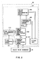
- Fig. 2 shows the detail of the plant diagnostic section 21 which includes a time series of difference calculation means 211, a time series of difference whiteness qualification means 212, a time constant determination means 213, an abnormality judgement means 215, a failure source determination means 216, and an alarm unit 217.
- plant signals such as plant manipulation signals and state signals which are this time applied from the object 19 to be diagnosed to the plant diagnostic section 21 are input from the time series of difference calculation means 211 to the plant diagnostic model 20, at which the next estimated value is calculated and this value is fed back to the time series of difference calculation means 211.
- the time series of difference calculation means 211 calculates the time series of difference ⁇ i (i represents an item number of the plant diagnostic model 20) i.e., a time series of difference between an estimated value and an actual value in respect of each plant value on the basis of the estimated value from the plant diagnostic model 20 and a value read from the object 19 to be diagnosed. After the deviation is calculated, the time series of difference calculation means 211 calculates an average per each item to calculate a residual by subtracting the average from respective deviations to output the time series of difference e. to the time series of difference whiteness qualification means 212.
- the time constant determination means 213 inputs AR model coefficient matrices A(l), A(2), ..., A(M) of the AR model expressed by the equation (1) from the plant diagnostic model 20 to calculate an impulse response I i (T) given by the change of a plant value (the item number i) with respect to the change of a plant value (the item number j) in accordance with the following equations (6.1), (6.2), (6.3) and (6.4).
- the time constant determination means 213 inputs AR model coefficient matrices A(l), A(2), ..., A(M) of the AR model expressed by the equation (14 from the plant diagnostic model 20 to calculate an impulse response a ij ( ⁇ ) given by the change of a certain plant value (item number i) with respect to the change of a certain plant value (item number j) to obtain sampling time which has the strongest influence on such a change.
- a value of the item number j in the (s) when only a value of the item number i is set to 1 and values of other item numbers are set to 0 in the (s-1) of the equation (6.2) is an impulse response given by the change of the plant value (item number i) before one sample with respect to the change of a certain value (the item number j).
- the impulse response a ll (2) given by the item number 1 before two samples with respect to the item number 1 is expressed as follows.
- time constant ⁇ ij of the plant value (item number j) with respect to the plant value (item number i) is calculated on the basis of the following definition. Namely, ⁇ .. is defined as a value of T which maximizes the absolute value of a ij (1), a ij (2), ..., a ij ( ⁇ ), a ij (M).
- the time constant ⁇ ij thus obtained indicates a sampling time duration which has the greatest influence of such a change on the plant value of the item number j.
- the time constant ⁇ ij thus obtained is output from the time series of difference whiteness qualification means 212.
- the time series of difference whiteness qualification means 212 receives the time series of difference ⁇ i output from the time series of difference calculation means 211 and the time constant ⁇ ij output from the time constant determination means 213 to calculate an index for qualifying whiteness of the time series of difference. For this, correlation function expressed by the following equation (8) is first calculated.
- the time series of difference ⁇ i since uncertainty of the plant diagnostic model is regarded as a negligible value, if the object 19 to be diagnosed is normal, the deviation ⁇ i occurs only when physical disturbance input is applied to the power generation plant 11. Accordingly, the time series of difference ⁇ i ordinarily becomes random values and therefore has whiteness. However, if any abnormality occurs in the object 19 to be diagnosed, the time series of difference ⁇ i has regularity.
- the above-mentioned whiteness qualification index AL ij is used as the index for qualifying regularity of the time series of difference ⁇ i .
- This index AL.. indicates to what degree the time series of difference ⁇ i is correlated with the time series of difference ⁇ j , which becomes zero when there is no correlation therebetween.
- AL ij indicates auto-correlation function, which serves as whiteness qualification index of the time series of difference ⁇ i itself.
- the abnormality judgement means 215 inputs the whiteness qualification index AL ij from the time series of difference whiteness qualification means 212 to judge the plant subject to diagnosis to be abnormal when the whiteness qualification index AL ij is above a certain value ARL which is determined based on ratio of the erroneous judgement as described later.
- the failure source determination means 216 inputs the whiteness qualification index AL.. from the time series of difference whiteness qualification means 212 and numbers corresponding to plant state variable and manipulated variable at an abnormal portion to determine the failure source. Particularly, the whiteness qualification index AL.. called auto-correlation function is used as index for determination of the failure source.
- the alarm unit 217 informs an operator of abnormality or information from the abnormality judgement means 215 and the failure source determination means 216.
- a burner provided in a fire furnace of a boiler BOI fuel FR is delivered through a pump FIP along with air AIR.
- water collected by a condenser CON is fed to the fire furnace of boiler BOI by means of a boiler feed water pump BFP.
- the water thus fed is changed into steam and then is delivered to a super heater SH.
- the steam is regulated so as to have predetermined temperature and pressure and the steam thus regulated is delivered to a high pressure turbine HP.
- the steam gives rotational force to the high pressure turbine HP to revolve a generator G, so that the steam having reduced temperature and pressure is obtained.
- the steam thus obtained is fed back to a reheater RH at which the process for increasing temperature and pressure is applied to the steam.
- the steam from the reheater RH is delivered to the low pressure turbine LP.
- the steam gives rotational force to the low pressure turbine LP to revolve the generator G, so that the steam having reduced temperature and pressure is obtained.
- the steam thus obtained is condensed into water by the condenser CON.
- the water thus obtained is circulated and delivered again to the boiler by the boiler feed water pump BFP.
- the above-mentioned three manipulated variables are water-fuel ratio (item number 1) of fuel FR, reheater gas damper GD (item number 2) and super heater spray SP (item number 3), and the above-mentioned four state variables are addition demand value MWD (item number 4), SH outlet temperature MST (item number 5), RH outlet temperature RHT (item number 6) and main steam pressure MSP (item number 7).
- the time series of difference calculation means 211 When the above-mentioned plant variables are input to the plant diagnostic section 21, the time series of difference calculation means 211 outputs these plant variables to the plant diagnostic model 20 and takes therein estimated values of plant variables obtained based on calculation in the plant diagnostic model 20 in accordance with the previous outputs. Thus, the time series of difference calculation means 211 compares these estimated values with plant values which are input this time from the object 19 to be diagnosed to calculate time series of difference ⁇ i of each plant variable to output the time series of difference Ei thus computed to the time series of difference whiteness qualification means 212.
- time constant determination means 213 inputs AR coefficient matrices A(l), A(2), ..., A(M) from the plant diagnostic model 20 to calculate time constant ⁇ ij in accordance with the above-mentioned equations (6.5) and (7) to output the time constant ⁇ ij thus calculated to the whiteness qualification means 212.
- the time series of difference whiteness qualification means 212 takes therein these time series of difference c. and time constant T .. to calculate whiteness i qualification index AL ij for judging relationship between items and abnormality or normarity to output the whiteness qualification index AL ij thus calculated to the abnormality judgement means 215 and to the failure source determination means 216.
- whiteness qualification index AL63 from the state variable with respect to the manipulated variable etc. in connection with the abnormality which actually would not occur in the actual plant, for instance, "the abnormality of SH outlet temperature of the item number 5 has influence on SH spray of the item number 3"
- the whiteness qualification index AL ij at this time depends upon the normal distribution (0, 1) (having average of 0 and dispersion of 1).
- the abnormality judgement means 215 inputs AL ij indicative of the auto-correlation function of the above-mentioned whiteness qualification index AL .. to judge the item number i which satisfies the following relationship to be abnormal:
- the failure source determination means 216 inputs AL.. (i ⁇ j) indicative of cross-correlation function of the above-mentioned whiteness qualification index AL ij and the item number i judged to be abnormal by the abnormality judgement means 215 to judge the abnormality of the state variable (the item number j) to be based on the failure of the manipulated variable (the item number i) in connection with the manipulated variable (the item number i) and the state variable (the item number j) of which both item numbers i and j are abnormal.
- a is a value such that
- 1.96 and each value of a does not indicate the same value, and indicates that calculation is not made on the basis of the relationship between the manipulated variable and the state variable.
- the abnormality judgement means 215 the item numbers 2 and 6 are judged to be abnormal. Then, in the failure source determination means 216, the abnormality of the item number 6 is judged to be based on the failure of the item number 2.
- the present invention may be implemented as follows.
- the diagnosis of the entirety of the plant including its control status can be carried out.
- the characteristic of the entire plant is first obtained from the plant diagnostic model in terms of time constant, and then the diagnosis is actually conducted. Accordingly, this makes it possible to identify abnormality or failure source in conformity with the characteristic of the object to be diagnosed.
- the plant since it is unnecessary to test the plant for obtaining the time constant, the plant can be effectively used as compared to other methods.
Landscapes
- Physics & Mathematics (AREA)
- Engineering & Computer Science (AREA)
- Artificial Intelligence (AREA)
- Evolutionary Computation (AREA)
- Mathematical Physics (AREA)
- General Physics & Mathematics (AREA)
- Automation & Control Theory (AREA)
- Testing And Monitoring For Control Systems (AREA)
Applications Claiming Priority (2)
| Application Number | Priority Date | Filing Date | Title |
|---|---|---|---|
| JP60208767A JPH0625930B2 (ja) | 1985-09-24 | 1985-09-24 | プラント診断装置 |
| JP208767/85 | 1985-09-24 |
Publications (3)
| Publication Number | Publication Date |
|---|---|
| EP0216356A2 true EP0216356A2 (de) | 1987-04-01 |
| EP0216356A3 EP0216356A3 (en) | 1989-05-10 |
| EP0216356B1 EP0216356B1 (de) | 1994-04-20 |
Family
ID=16561750
Family Applications (1)
| Application Number | Title | Priority Date | Filing Date |
|---|---|---|---|
| EP86113085A Expired - Lifetime EP0216356B1 (de) | 1985-09-24 | 1986-09-23 | Anlagen-Diagnosesystem |
Country Status (5)
| Country | Link |
|---|---|
| US (1) | US4755925A (de) |
| EP (1) | EP0216356B1 (de) |
| JP (1) | JPH0625930B2 (de) |
| CA (1) | CA1259700A (de) |
| DE (1) | DE3689800T2 (de) |
Cited By (5)
| Publication number | Priority date | Publication date | Assignee | Title |
|---|---|---|---|---|
| EP0553571A1 (de) * | 1992-01-17 | 1993-08-04 | Westinghouse Electric Corporation | Methode zum Erzeugen und Ausführen von komplexen Verfahren |
| FR2692688A1 (fr) * | 1992-06-19 | 1993-12-24 | Cegelec | Procédé de régulation d'un processus continu comportant une phase d'optimisation d'un modèle et une phase de régulation. |
| SG107131A1 (en) * | 2000-06-22 | 2004-11-29 | Hitachi Ltd | A power plant operation control system and a power plant maintaining and managing method |
| DE4447288B4 (de) * | 1993-12-30 | 2007-10-11 | Caterpillar Inc., Peoria | Maschinenfehlerdiagnosesystem und -verfahren |
| RU2327197C1 (ru) * | 2007-01-09 | 2008-06-20 | Государственное образовательное учреждение высшего профессионального образования Кузбасская государственная педагогическая академия (КузГПА) | Способ фрагментального управления и идентификации канала регулирования состояния объекта в действующей системе |
Families Citing this family (31)
| Publication number | Priority date | Publication date | Assignee | Title |
|---|---|---|---|---|
| DE3741713A1 (de) * | 1987-12-09 | 1989-06-22 | Bbc Brown Boveri & Cie | Verfahren zum schutz der gate-unit fuer einen gto-thyristor |
| JPH06101079B2 (ja) * | 1988-11-09 | 1994-12-12 | 三菱電機株式会社 | プラント異常診断装置 |
| US5315502A (en) * | 1989-06-09 | 1994-05-24 | Mitsubishi Denki Kabushiki Kaisha | Plant operation support apparatus and method using expert systems |
| IE902596A1 (en) * | 1989-07-17 | 1991-02-27 | Williams Technology | Monitoring and control of oil/gas fields |
| US5214577A (en) * | 1990-10-24 | 1993-05-25 | Osaka Gas Co., Ltd. | Automatic test generation for model-based real-time fault diagnostic systems |
| US5465321A (en) * | 1993-04-07 | 1995-11-07 | The United States Of America As Represented By The Administrator Of The National Aeronautics And Space Administration | Hidden markov models for fault detection in dynamic systems |
| US5642296A (en) * | 1993-07-29 | 1997-06-24 | Texas Instruments Incorporated | Method of diagnosing malfunctions in semiconductor manufacturing equipment |
| JP2829241B2 (ja) * | 1994-07-26 | 1998-11-25 | 三菱電機株式会社 | プラント支援装置 |
| DE19517104A1 (de) * | 1995-05-10 | 1996-11-14 | Istec Gmbh | Verfahren zur Zustandsüberwachung dynamischer Rauschprozesse |
| AU2562997A (en) * | 1996-04-29 | 1997-11-19 | Pulp And Paper Research Institute Of Canada | Automatic control loop monitoring and diagnostics |
| US5798950A (en) * | 1996-10-31 | 1998-08-25 | International Business Machines Corporation | Method and apparatus for estimating durations of activities in forming a current system, based on past durations of activities in forming past systems |
| DE19732046A1 (de) * | 1997-07-25 | 1999-01-28 | Abb Patent Gmbh | Prozeßdiagnosesystem und Verfahren zur Diagnose von Vorgängen und Zuständen eines technischen Prozesses |
| SE515570C2 (sv) | 1999-10-05 | 2001-09-03 | Abb Ab | Ett datorbaserat förfarande och system för reglering av en industriell process |
| GB2379752A (en) * | 2001-06-05 | 2003-03-19 | Abb Ab | Root cause analysis under conditions of uncertainty |
| JP3844217B2 (ja) * | 2002-04-03 | 2006-11-08 | ソニー株式会社 | 信号処理システム、信号出力装置、信号入力装置及び通信制御方法 |
| US20050165748A1 (en) * | 2004-01-15 | 2005-07-28 | Seagate Technology Llc | Method and apparatus for querying a computerized database |
| RU2276396C2 (ru) * | 2004-03-22 | 2006-05-10 | Кузбасская государственная педагогическая академия (КузГПА) | Способ идентификации объектов с изменением заданий |
| RU2271561C2 (ru) * | 2004-06-01 | 2006-03-10 | Государственное образовательное учреждение высшего профессионального образования Кузбасская государственная педагогическая академия (КузГПА) | Способ идентификации каналов регулирования объектов с нанесением пробных сигналов на прогнозируемые рабочие управления |
| US7415328B2 (en) * | 2004-10-04 | 2008-08-19 | United Technologies Corporation | Hybrid model based fault detection and isolation system |
| US20090089031A1 (en) * | 2007-09-28 | 2009-04-02 | Rockwell Automation Technologies, Inc. | Integrated simulation of controllers and devices |
| US7801710B2 (en) * | 2007-09-28 | 2010-09-21 | Rockwell Automation Technologies, Inc. | Simulation controls for model variability and randomness |
| US8548777B2 (en) * | 2007-09-28 | 2013-10-01 | Rockwell Automation Technologies, Inc. | Automated recommendations from simulation |
| US20090089234A1 (en) * | 2007-09-28 | 2009-04-02 | Rockwell Automation Technologies, Inc. | Automated code generation for simulators |
| US20090089029A1 (en) * | 2007-09-28 | 2009-04-02 | Rockwell Automation Technologies, Inc. | Enhanced execution speed to improve simulation performance |
| US8069021B2 (en) * | 2007-09-28 | 2011-11-29 | Rockwell Automation Technologies, Inc. | Distributed simulation and synchronization |
| US7836355B2 (en) * | 2007-12-03 | 2010-11-16 | International Business Machines Corporation | Automatic maintenance of a computing system in a steady state using correlation |
| US8352723B2 (en) * | 2009-10-06 | 2013-01-08 | International Business Machines Corporation | Automatic maintenance of a computing system in a steady state using correlation |
| RU2459225C1 (ru) * | 2011-06-16 | 2012-08-20 | Государственное образовательное учреждение высшего профессионального образования "Оренбургский государственный университет" | Способ выработки управляющего воздействия для промышленного объекта управления с двухэтапным рабочим процессом |
| KR102340395B1 (ko) * | 2020-01-02 | 2021-12-15 | 두산중공업 주식회사 | 플랜트의 고장을 진단하기 위한 장치 및 이를 위한 방법 |
| JP7499671B2 (ja) | 2020-10-07 | 2024-06-14 | 三菱重工業株式会社 | 性能評価方法、運転制御方法、性能評価装置、及びプログラム |
| DE102021212115A1 (de) | 2021-10-27 | 2023-04-27 | Robert Bosch Gesellschaft mit beschränkter Haftung | Verfahren und Vorrichtung zur Diagnose einer Funktion von Gassystemaktuatoren mithilfe von maschinellen Lernverfahren |
Family Cites Families (6)
| Publication number | Priority date | Publication date | Assignee | Title |
|---|---|---|---|---|
| US4349869A (en) * | 1979-10-01 | 1982-09-14 | Shell Oil Company | Dynamic matrix control method |
| JPS5685507A (en) * | 1979-12-17 | 1981-07-11 | Hitachi Ltd | Monitoring method of performance of steam turbine plant |
| JPS59229622A (ja) * | 1983-06-10 | 1984-12-24 | Toshiba Corp | プラント診断装置 |
| DE3390539C2 (de) * | 1983-10-14 | 1990-03-08 | Ford Werke Ag | Verfahren zum Betreiben eines adaptiv gesteuerten technischen Prozesses |
| JPS60171507A (ja) * | 1984-02-16 | 1985-09-05 | Nippon Atom Ind Group Co Ltd | プラントの異常診断方法 |
| US4517468A (en) * | 1984-04-30 | 1985-05-14 | Westinghouse Electric Corp. | Diagnostic system and method |
-
1985
- 1985-09-24 JP JP60208767A patent/JPH0625930B2/ja not_active Expired - Lifetime
-
1986
- 1986-09-23 CA CA000518811A patent/CA1259700A/en not_active Expired
- 1986-09-23 EP EP86113085A patent/EP0216356B1/de not_active Expired - Lifetime
- 1986-09-23 DE DE3689800T patent/DE3689800T2/de not_active Expired - Fee Related
- 1986-09-23 US US06/910,687 patent/US4755925A/en not_active Expired - Fee Related
Cited By (9)
| Publication number | Priority date | Publication date | Assignee | Title |
|---|---|---|---|---|
| EP0553571A1 (de) * | 1992-01-17 | 1993-08-04 | Westinghouse Electric Corporation | Methode zum Erzeugen und Ausführen von komplexen Verfahren |
| US5553304A (en) * | 1992-01-17 | 1996-09-03 | Westinghouse Electric Corporation | Method for generating and executing complex operating procedures |
| CN1048100C (zh) * | 1992-01-17 | 2000-01-05 | 西屋电气公司 | 产生并执行复杂运行过程的方法 |
| FR2692688A1 (fr) * | 1992-06-19 | 1993-12-24 | Cegelec | Procédé de régulation d'un processus continu comportant une phase d'optimisation d'un modèle et une phase de régulation. |
| BE1006423A3 (fr) * | 1992-06-19 | 1994-08-23 | Cegelec | Procede de regulation d'un processus continu comportant une phase d'optimisation et une phase de regulation. |
| ES2076088A2 (es) * | 1992-06-19 | 1995-10-16 | Cegelec Sa | Procedimiento para la regulacion de un proceso continuo que comprende una fase de optimado y una fase de regulacion. |
| DE4447288B4 (de) * | 1993-12-30 | 2007-10-11 | Caterpillar Inc., Peoria | Maschinenfehlerdiagnosesystem und -verfahren |
| SG107131A1 (en) * | 2000-06-22 | 2004-11-29 | Hitachi Ltd | A power plant operation control system and a power plant maintaining and managing method |
| RU2327197C1 (ru) * | 2007-01-09 | 2008-06-20 | Государственное образовательное учреждение высшего профессионального образования Кузбасская государственная педагогическая академия (КузГПА) | Способ фрагментального управления и идентификации канала регулирования состояния объекта в действующей системе |
Also Published As
| Publication number | Publication date |
|---|---|
| EP0216356A3 (en) | 1989-05-10 |
| CA1259700A (en) | 1989-09-19 |
| EP0216356B1 (de) | 1994-04-20 |
| DE3689800D1 (de) | 1994-05-26 |
| DE3689800T2 (de) | 1994-10-13 |
| JPS6270914A (ja) | 1987-04-01 |
| JPH0625930B2 (ja) | 1994-04-06 |
| US4755925A (en) | 1988-07-05 |
Similar Documents
| Publication | Publication Date | Title |
|---|---|---|
| EP0216356A2 (de) | Anlagen-Diagnosesystem | |
| US4630189A (en) | System for determining abnormal plant operation based on whiteness indexes | |
| US4298955A (en) | Method of and apparatus for the detection and analysis of hazards | |
| EP1676179B1 (de) | Erkennung von fehlern von systemkomponenten in einem kontinuierlichen prozess | |
| EP0315307B1 (de) | Leistungsdatenverarbeitungssystem | |
| EP0170516B1 (de) | Diagnostikgerät | |
| US5210704A (en) | System for prognosis and diagnostics of failure and wearout monitoring and for prediction of life expectancy of helicopter gearboxes and other rotating equipment | |
| RU2667691C1 (ru) | Способ диагностирования неисправности и система диагностирования неисправности | |
| EP0925491B1 (de) | Ereignisfeststellung mit kurzen und langen Mittelwerten | |
| US5414798A (en) | Knowledge information generating system | |
| Thomson et al. | Statistical process control based fault detection of CHP units | |
| DePold et al. | The application of expert systems and neural networks to gas turbine prognostics and diagnostics | |
| KR0136785B1 (ko) | 다수의 동일한 공정파라미터를 모니터링하는 시스템 및 그 방법 | |
| Dewallef et al. | On-line aircraft engine diagnostic using a soft-constrained Kalman filter | |
| Gorbiychuk et al. | Evaluation of dynamic properties of gas pumping units according to the results of experimental researches | |
| RU2056506C1 (ru) | Способ определения технического состояния системы автоматического регулирования турбоагрегата | |
| US6463347B1 (en) | System for detecting occurrence of an event when the slope of change based upon difference of short and long term averages exceeds a predetermined limit | |
| EP0359395B1 (de) | Dateneingabe in einem Expertensystem | |
| Black et al. | Inferential Neural Networks for Nuclear Power Plant Sensor Channel Drift Monitoring | |
| RU2781738C2 (ru) | Способ функционального диагностирования жидкостного ракетного двигателя при огневом испытании | |
| Campbell | Instrument failure detection using functional redundancy applied to a nuclear pressurizer.[PWR] | |
| Hines et al. | An evaluation of instrument calibration monitoring using artificial neural networks | |
| Uhrig et al. | Integration of artificial intelligence systems for nuclear power plant surveillance and diagnostics | |
| JPS59154320A (ja) | センサ群の異常診断方法 | |
| Pooley et al. | Embedded expert system for space shuttle main engine maintenance |
Legal Events
| Date | Code | Title | Description |
|---|---|---|---|
| PUAI | Public reference made under article 153(3) epc to a published international application that has entered the european phase |
Free format text: ORIGINAL CODE: 0009012 |
|
| 17P | Request for examination filed |
Effective date: 19861021 |
|
| AK | Designated contracting states |
Kind code of ref document: A2 Designated state(s): DE FR GB |
|
| PUAL | Search report despatched |
Free format text: ORIGINAL CODE: 0009013 |
|
| AK | Designated contracting states |
Kind code of ref document: A3 Designated state(s): DE FR GB |
|
| 17Q | First examination report despatched |
Effective date: 19911015 |
|
| GRAA | (expected) grant |
Free format text: ORIGINAL CODE: 0009210 |
|
| AK | Designated contracting states |
Kind code of ref document: B1 Designated state(s): DE FR GB |
|
| REF | Corresponds to: |
Ref document number: 3689800 Country of ref document: DE Date of ref document: 19940526 |
|
| ET | Fr: translation filed | ||
| PLBE | No opposition filed within time limit |
Free format text: ORIGINAL CODE: 0009261 |
|
| STAA | Information on the status of an ep patent application or granted ep patent |
Free format text: STATUS: NO OPPOSITION FILED WITHIN TIME LIMIT |
|
| 26N | No opposition filed | ||
| PGFP | Annual fee paid to national office [announced via postgrant information from national office to epo] |
Ref country code: FR Payment date: 19990909 Year of fee payment: 14 |
|
| PGFP | Annual fee paid to national office [announced via postgrant information from national office to epo] |
Ref country code: GB Payment date: 19990922 Year of fee payment: 14 |
|
| PGFP | Annual fee paid to national office [announced via postgrant information from national office to epo] |
Ref country code: DE Payment date: 19990927 Year of fee payment: 14 |
|
| PG25 | Lapsed in a contracting state [announced via postgrant information from national office to epo] |
Ref country code: GB Free format text: LAPSE BECAUSE OF NON-PAYMENT OF DUE FEES Effective date: 20000923 |
|
| GBPC | Gb: european patent ceased through non-payment of renewal fee |
Effective date: 20000923 |
|
| PG25 | Lapsed in a contracting state [announced via postgrant information from national office to epo] |
Ref country code: FR Free format text: LAPSE BECAUSE OF NON-PAYMENT OF DUE FEES Effective date: 20010531 |
|
| PG25 | Lapsed in a contracting state [announced via postgrant information from national office to epo] |
Ref country code: DE Free format text: LAPSE BECAUSE OF NON-PAYMENT OF DUE FEES Effective date: 20010601 |
|
| REG | Reference to a national code |
Ref country code: FR Ref legal event code: ST |