EP0216493A1 - Récupération de platine à l'aide de grilles résistant à la perforation - Google Patents
Récupération de platine à l'aide de grilles résistant à la perforation Download PDFInfo
- Publication number
- EP0216493A1 EP0216493A1 EP19860306362 EP86306362A EP0216493A1 EP 0216493 A1 EP0216493 A1 EP 0216493A1 EP 19860306362 EP19860306362 EP 19860306362 EP 86306362 A EP86306362 A EP 86306362A EP 0216493 A1 EP0216493 A1 EP 0216493A1
- Authority
- EP
- European Patent Office
- Prior art keywords
- gauze
- recovery
- catalyst
- platinum
- nitrogen
- Prior art date
- Legal status (The legal status is an assumption and is not a legal conclusion. Google has not performed a legal analysis and makes no representation as to the accuracy of the status listed.)
- Withdrawn
Links
- 238000011084 recovery Methods 0.000 title claims abstract description 300
- BASFCYQUMIYNBI-UHFFFAOYSA-N platinum Chemical compound [Pt] BASFCYQUMIYNBI-UHFFFAOYSA-N 0.000 title claims abstract description 284
- 229910052697 platinum Inorganic materials 0.000 title claims abstract description 132
- KDLHZDBZIXYQEI-UHFFFAOYSA-N Palladium Chemical compound [Pd] KDLHZDBZIXYQEI-UHFFFAOYSA-N 0.000 claims abstract description 169
- 239000003054 catalyst Substances 0.000 claims abstract description 162
- 229910052763 palladium Inorganic materials 0.000 claims abstract description 95
- 239000010931 gold Substances 0.000 claims abstract description 59
- 229910052737 gold Inorganic materials 0.000 claims abstract description 54
- PCHJSUWPFVWCPO-UHFFFAOYSA-N gold Chemical compound [Au] PCHJSUWPFVWCPO-UHFFFAOYSA-N 0.000 claims abstract description 39
- 238000012546 transfer Methods 0.000 claims abstract description 26
- GRYLNZFGIOXLOG-UHFFFAOYSA-N Nitric acid Chemical compound O[N+]([O-])=O GRYLNZFGIOXLOG-UHFFFAOYSA-N 0.000 claims abstract description 20
- 229910017604 nitric acid Inorganic materials 0.000 claims abstract description 20
- QGZKDVFQNNGYKY-UHFFFAOYSA-N Ammonia Chemical compound N QGZKDVFQNNGYKY-UHFFFAOYSA-N 0.000 claims description 204
- IJGRMHOSHXDMSA-UHFFFAOYSA-N Atomic nitrogen Chemical compound N#N IJGRMHOSHXDMSA-UHFFFAOYSA-N 0.000 claims description 162
- 229910021529 ammonia Inorganic materials 0.000 claims description 93
- 229910052757 nitrogen Inorganic materials 0.000 claims description 81
- 238000000034 method Methods 0.000 claims description 67
- 238000011068 loading method Methods 0.000 claims description 64
- MWUXSHHQAYIFBG-UHFFFAOYSA-N nitrogen oxide Inorganic materials O=[N] MWUXSHHQAYIFBG-UHFFFAOYSA-N 0.000 claims description 51
- 239000011800 void material Substances 0.000 claims description 42
- PXHVJJICTQNCMI-UHFFFAOYSA-N Nickel Chemical compound [Ni] PXHVJJICTQNCMI-UHFFFAOYSA-N 0.000 claims description 39
- 230000008569 process Effects 0.000 claims description 33
- 229910052759 nickel Inorganic materials 0.000 claims description 25
- 239000007789 gas Substances 0.000 claims description 20
- 229910000069 nitrogen hydride Inorganic materials 0.000 claims description 18
- 230000006872 improvement Effects 0.000 claims description 11
- 238000011144 upstream manufacturing Methods 0.000 claims description 10
- 238000009792 diffusion process Methods 0.000 claims description 7
- 230000003647 oxidation Effects 0.000 description 34
- 238000007254 oxidation reaction Methods 0.000 description 34
- 238000006243 chemical reaction Methods 0.000 description 25
- 229910045601 alloy Inorganic materials 0.000 description 24
- 239000000956 alloy Substances 0.000 description 24
- 239000010948 rhodium Substances 0.000 description 17
- 229910052703 rhodium Inorganic materials 0.000 description 15
- 238000003556 assay Methods 0.000 description 13
- 230000008961 swelling Effects 0.000 description 12
- 230000006870 function Effects 0.000 description 11
- 238000013461 design Methods 0.000 description 10
- MHOVAHRLVXNVSD-UHFFFAOYSA-N rhodium atom Chemical compound [Rh] MHOVAHRLVXNVSD-UHFFFAOYSA-N 0.000 description 10
- 238000002844 melting Methods 0.000 description 9
- 230000008018 melting Effects 0.000 description 9
- 239000000047 product Substances 0.000 description 7
- 229910001252 Pd alloy Inorganic materials 0.000 description 6
- 230000000694 effects Effects 0.000 description 6
- 229910052751 metal Inorganic materials 0.000 description 6
- 239000002184 metal Substances 0.000 description 6
- 230000000052 comparative effect Effects 0.000 description 5
- 238000010438 heat treatment Methods 0.000 description 5
- 238000012360 testing method Methods 0.000 description 5
- 238000005275 alloying Methods 0.000 description 4
- QVGXLLKOCUKJST-UHFFFAOYSA-N atomic oxygen Chemical compound [O] QVGXLLKOCUKJST-UHFFFAOYSA-N 0.000 description 4
- 230000015572 biosynthetic process Effects 0.000 description 4
- 238000004519 manufacturing process Methods 0.000 description 4
- 239000000203 mixture Substances 0.000 description 4
- 229910052760 oxygen Inorganic materials 0.000 description 4
- 239000001301 oxygen Substances 0.000 description 4
- CWYNVVGOOAEACU-UHFFFAOYSA-N Fe2+ Chemical compound [Fe+2] CWYNVVGOOAEACU-UHFFFAOYSA-N 0.000 description 3
- 208000021017 Weight Gain Diseases 0.000 description 3
- 238000007689 inspection Methods 0.000 description 3
- MUMZUERVLWJKNR-UHFFFAOYSA-N oxoplatinum Chemical compound [Pt]=O MUMZUERVLWJKNR-UHFFFAOYSA-N 0.000 description 3
- 229910003446 platinum oxide Inorganic materials 0.000 description 3
- 239000010970 precious metal Substances 0.000 description 3
- 229910052707 ruthenium Inorganic materials 0.000 description 3
- 238000004088 simulation Methods 0.000 description 3
- 230000004584 weight gain Effects 0.000 description 3
- 235000019786 weight gain Nutrition 0.000 description 3
- 230000004580 weight loss Effects 0.000 description 3
- 229910001020 Au alloy Inorganic materials 0.000 description 2
- VYZAMTAEIAYCRO-UHFFFAOYSA-N Chromium Chemical compound [Cr] VYZAMTAEIAYCRO-UHFFFAOYSA-N 0.000 description 2
- UFHFLCQGNIYNRP-UHFFFAOYSA-N Hydrogen Chemical compound [H][H] UFHFLCQGNIYNRP-UHFFFAOYSA-N 0.000 description 2
- 229910000990 Ni alloy Inorganic materials 0.000 description 2
- -1 Platinum Metals Chemical class 0.000 description 2
- 229910001260 Pt alloy Inorganic materials 0.000 description 2
- KJTLSVCANCCWHF-UHFFFAOYSA-N Ruthenium Chemical compound [Ru] KJTLSVCANCCWHF-UHFFFAOYSA-N 0.000 description 2
- 238000004364 calculation method Methods 0.000 description 2
- 230000008859 change Effects 0.000 description 2
- 229910052804 chromium Inorganic materials 0.000 description 2
- 239000011651 chromium Substances 0.000 description 2
- 230000003247 decreasing effect Effects 0.000 description 2
- 238000005516 engineering process Methods 0.000 description 2
- 238000002474 experimental method Methods 0.000 description 2
- 239000008246 gaseous mixture Substances 0.000 description 2
- 239000001257 hydrogen Substances 0.000 description 2
- 229910052739 hydrogen Inorganic materials 0.000 description 2
- 229910000953 kanthal Inorganic materials 0.000 description 2
- WPBNNNQJVZRUHP-UHFFFAOYSA-L manganese(2+);methyl n-[[2-(methoxycarbonylcarbamothioylamino)phenyl]carbamothioyl]carbamate;n-[2-(sulfidocarbothioylamino)ethyl]carbamodithioate Chemical compound [Mn+2].[S-]C(=S)NCCNC([S-])=S.COC(=O)NC(=S)NC1=CC=CC=C1NC(=S)NC(=O)OC WPBNNNQJVZRUHP-UHFFFAOYSA-L 0.000 description 2
- 239000000463 material Substances 0.000 description 2
- 238000005259 measurement Methods 0.000 description 2
- 150000002739 metals Chemical class 0.000 description 2
- 230000003094 perturbing effect Effects 0.000 description 2
- 230000000704 physical effect Effects 0.000 description 2
- 230000001052 transient effect Effects 0.000 description 2
- PCTMTFRHKVHKIS-BMFZQQSSSA-N (1s,3r,4e,6e,8e,10e,12e,14e,16e,18s,19r,20r,21s,25r,27r,30r,31r,33s,35r,37s,38r)-3-[(2r,3s,4s,5s,6r)-4-amino-3,5-dihydroxy-6-methyloxan-2-yl]oxy-19,25,27,30,31,33,35,37-octahydroxy-18,20,21-trimethyl-23-oxo-22,39-dioxabicyclo[33.3.1]nonatriaconta-4,6,8,10 Chemical compound C1C=C2C[C@@H](OS(O)(=O)=O)CC[C@]2(C)[C@@H]2[C@@H]1[C@@H]1CC[C@H]([C@H](C)CCCC(C)C)[C@@]1(C)CC2.O[C@H]1[C@@H](N)[C@H](O)[C@@H](C)O[C@H]1O[C@H]1/C=C/C=C/C=C/C=C/C=C/C=C/C=C/[C@H](C)[C@@H](O)[C@@H](C)[C@H](C)OC(=O)C[C@H](O)C[C@H](O)CC[C@@H](O)[C@H](O)C[C@H](O)C[C@](O)(C[C@H](O)[C@H]2C(O)=O)O[C@H]2C1 PCTMTFRHKVHKIS-BMFZQQSSSA-N 0.000 description 1
- 238000012935 Averaging Methods 0.000 description 1
- ZOXJGFHDIHLPTG-UHFFFAOYSA-N Boron Chemical compound [B] ZOXJGFHDIHLPTG-UHFFFAOYSA-N 0.000 description 1
- OKTJSMMVPCPJKN-UHFFFAOYSA-N Carbon Chemical compound [C] OKTJSMMVPCPJKN-UHFFFAOYSA-N 0.000 description 1
- RYGMFSIKBFXOCR-UHFFFAOYSA-N Copper Chemical compound [Cu] RYGMFSIKBFXOCR-UHFFFAOYSA-N 0.000 description 1
- 229910000629 Rh alloy Inorganic materials 0.000 description 1
- RTAQQCXQSZGOHL-UHFFFAOYSA-N Titanium Chemical compound [Ti] RTAQQCXQSZGOHL-UHFFFAOYSA-N 0.000 description 1
- QCWXUUIWCKQGHC-UHFFFAOYSA-N Zirconium Chemical compound [Zr] QCWXUUIWCKQGHC-UHFFFAOYSA-N 0.000 description 1
- 238000007792 addition Methods 0.000 description 1
- 230000004075 alteration Effects 0.000 description 1
- 230000003466 anti-cipated effect Effects 0.000 description 1
- 238000013459 approach Methods 0.000 description 1
- 238000000429 assembly Methods 0.000 description 1
- 230000000712 assembly Effects 0.000 description 1
- 230000009286 beneficial effect Effects 0.000 description 1
- 230000008901 benefit Effects 0.000 description 1
- 229910052796 boron Inorganic materials 0.000 description 1
- 229910052799 carbon Inorganic materials 0.000 description 1
- 239000007795 chemical reaction product Substances 0.000 description 1
- 238000002485 combustion reaction Methods 0.000 description 1
- 238000001816 cooling Methods 0.000 description 1
- 229910052802 copper Inorganic materials 0.000 description 1
- 239000010949 copper Substances 0.000 description 1
- 230000001351 cycling effect Effects 0.000 description 1
- 238000000354 decomposition reaction Methods 0.000 description 1
- 230000007423 decrease Effects 0.000 description 1
- 238000010586 diagram Methods 0.000 description 1
- 238000005530 etching Methods 0.000 description 1
- 239000000446 fuel Substances 0.000 description 1
- 239000003353 gold alloy Substances 0.000 description 1
- 230000000977 initiatory effect Effects 0.000 description 1
- 238000009434 installation Methods 0.000 description 1
- 230000003993 interaction Effects 0.000 description 1
- 230000007246 mechanism Effects 0.000 description 1
- 238000002156 mixing Methods 0.000 description 1
- 238000012986 modification Methods 0.000 description 1
- 230000004048 modification Effects 0.000 description 1
- 229910052758 niobium Inorganic materials 0.000 description 1
- 239000010955 niobium Substances 0.000 description 1
- GUCVJGMIXFAOAE-UHFFFAOYSA-N niobium atom Chemical compound [Nb] GUCVJGMIXFAOAE-UHFFFAOYSA-N 0.000 description 1
- 238000012856 packing Methods 0.000 description 1
- 150000002941 palladium compounds Chemical class 0.000 description 1
- 239000002245 particle Substances 0.000 description 1
- PXXKQOPKNFECSZ-UHFFFAOYSA-N platinum rhodium Chemical compound [Rh].[Pt] PXXKQOPKNFECSZ-UHFFFAOYSA-N 0.000 description 1
- 230000001737 promoting effect Effects 0.000 description 1
- 230000001105 regulatory effect Effects 0.000 description 1
- 230000000717 retained effect Effects 0.000 description 1
- 238000012552 review Methods 0.000 description 1
- 229910052709 silver Inorganic materials 0.000 description 1
- 239000004332 silver Substances 0.000 description 1
- 239000007787 solid Substances 0.000 description 1
- 229910052715 tantalum Inorganic materials 0.000 description 1
- GUVRBAGPIYLISA-UHFFFAOYSA-N tantalum atom Chemical compound [Ta] GUVRBAGPIYLISA-UHFFFAOYSA-N 0.000 description 1
- 238000005382 thermal cycling Methods 0.000 description 1
- 229910052719 titanium Inorganic materials 0.000 description 1
- 239000010936 titanium Substances 0.000 description 1
- 230000035899 viability Effects 0.000 description 1
- 229910052726 zirconium Inorganic materials 0.000 description 1
Images


Classifications
-
- C—CHEMISTRY; METALLURGY
- C22—METALLURGY; FERROUS OR NON-FERROUS ALLOYS; TREATMENT OF ALLOYS OR NON-FERROUS METALS
- C22B—PRODUCTION AND REFINING OF METALS; PRETREATMENT OF RAW MATERIALS
- C22B7/00—Working up raw materials other than ores, e.g. scrap, to produce non-ferrous metals and compounds thereof; Methods of a general interest or applied to the winning of more than two metals
- C22B7/009—General processes for recovering metals or metallic compounds from spent catalysts
-
- C—CHEMISTRY; METALLURGY
- C22—METALLURGY; FERROUS OR NON-FERROUS ALLOYS; TREATMENT OF ALLOYS OR NON-FERROUS METALS
- C22B—PRODUCTION AND REFINING OF METALS; PRETREATMENT OF RAW MATERIALS
- C22B11/00—Obtaining noble metals
- C22B11/02—Obtaining noble metals by dry processes
-
- Y—GENERAL TAGGING OF NEW TECHNOLOGICAL DEVELOPMENTS; GENERAL TAGGING OF CROSS-SECTIONAL TECHNOLOGIES SPANNING OVER SEVERAL SECTIONS OF THE IPC; TECHNICAL SUBJECTS COVERED BY FORMER USPC CROSS-REFERENCE ART COLLECTIONS [XRACs] AND DIGESTS
- Y02—TECHNOLOGIES OR APPLICATIONS FOR MITIGATION OR ADAPTATION AGAINST CLIMATE CHANGE
- Y02P—CLIMATE CHANGE MITIGATION TECHNOLOGIES IN THE PRODUCTION OR PROCESSING OF GOODS
- Y02P10/00—Technologies related to metal processing
- Y02P10/20—Recycling
Definitions
- Nitric acid is produced commercially by passing ammonia and air over an oxidation catalyst which is usually a gauze woven from platinum-rhodium alloy wire.
- an oxidation catalyst which is usually a gauze woven from platinum-rhodium alloy wire.
- the temperature of gas leaving the gauze ranges from about 810°C. to about 960°C., most often above 850°C.
- platinum is slowly lost from the gauze, possibly in the form of the more volatile oxides.
- Rhodium is also lost, but this is not so severe a problem.
- the rate of loss depends upon the type of plant. Typically, for each ton of ammonia converted, a high pressure plant will lose more than one gram of platinum, while lower pressure plants will lose less. Even though the rate of catalyst loss is slow when expressed in terms of weight, the cost is usually quite substantial. In many operations, the cost of platinum lost during production has been said to be the second largest expense of the operation, exceeded only by the cost of ammonia feedstock.
- a variety of alloying elements have been selected, mainly for their ability to improve the mechanical properties of palladium.
- Typical commercial palladium alloys have contained about 80% palladium and 20% gold by weight.
- the recovery alloys are usually employed in the form of multiple sheets of woven gauze but knitted meshes or other foraminous elements can also be used.
- the recovery gauze is usually placed as close as possible to the catalyst gauze, often within a few millimeters, usually no more than 10 mm.
- gauzes designed according to the present invention it is possible to obtain perforation resistant gauzes which also provide good recovery efficiency.
- the method of the present invention is especially desirable for use in high and medium pressure plants, since not only is more platinum lost per ton of ammonia converted, but also the number of tons of ammonia processed per unit area is much greater than in lower pressure plants and the severity of the perforation problem seens to increase with the operating velocity of the plants. Further, prior art single gauze recovery efficiencies for high pressure plants have been distressfully low, as recovering platinum in these plants is extremely difficult. Thus, any improvement is particularly significant for the economics of these plants.
- Recovery gauzes are designed and fabricated by the process comprising the steps of
- recovery efficiencies can be estimated for gauzes until an optimum configuration is determined, which will have an average recovery efficiency exceeding that given in column.2 of Table I.
- the initial product of the mesh and wire diameter exceeds at least about 0.2 for gauzes containing a major proportion of palladium and a minor proportion of nickel.
- the initial product of the mesh and the wire diameter will be in the range of from about 0.2 to about 0.9.
- the initial product of the mesh and wire diameter should be at least 0.3 and preferably in the range of from about 0.3 to about 0.9, more preferably from about 0.35 to about 0.9.
- the mesh N be in the range of from about 10 to about 80, d is in the range of from about 0.003 to about 0.090 inches, and their respective values are such that the initial product of N and d w is greater than at least about 0.2.
- the preferred gauzes consist essentially of at least about 88% Pd and from about 2% to about 12% gold having initial void fractions in excess of about 0.70 for medium velocity plants (above 50 tons of N 2 in NH 3 per sq. m. per day) and in excess of about 0.75 for high pressure plants (above 80 tons of N 2 in NH 3 per sq. m. per day).
- N is the mesh or number of wires per inch
- equation 1 will work adequately with values for "C” of .94 and for 'm" of .7 for the screens, reactors and flow conditions described in this application, if the values of Schmidt number and viscosity given below are used, even though the diffusing species may not necessarily be platinum oxide.
- efficiency vs. wire diameter graphs similar to Figures 1, 2 and 3 can be constructed using formula 1.
- the properties of the gas streams vary only by small amounts over the temperature ranges encountered in practice of from about 810° to about 960°, so that properties at 900°C. can be used with only slight error.
- the concentration of the feed to the catalyst is normally regulated to between 10.0 to 10.5 m /o (mole percent) ammonia and 90.0 to 89.5 m /o air, so the composition of the reaction products from the catalyst gauze remains constant, so that physical properties in that range can be used.
- the Schmidt No. is about .9 - .95 for diffusion of platinum oxide vapors in air and the dynamic viscosity of the gas is about 42 x 10-5 poise.
- the efficiency ⁇ is determined primarily by the mesh "N", and_wire diameter "d w ", for a given nitrogen loading "L", where the nitrogen loading "L” is the number of short tons of nitrogen (in ammonia) passed through each square meter of the catalyst gauze per day.
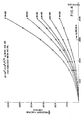
- efficiency can be plotted as a function of wire diameter for a variety of mesh sizes.
- void fraction can be shown parametrically on the same graph, so that efficiency and the void fraction can be determined simultaneously for each given combination of wire diameter and mesh.
- the pressure drop through the gauze can be estimated using known correlations.
- volumetric void fraction ( ⁇ ) be between about 0.76 and about 0.5.
- Volumetric void fractions from about 0.5 down to about 0.3 can provide even better recovery efficiencies, but care must be exercised to properly support the recovery gauze so that it is not damaged or displaced by the force of the stream of gas passing through it.
- volumetric void fractions between about 0.685 and about 0.5 will provide an excellent combination of especially high recovery efficiency with acceptable pressure drop.
- Void fractions of about 0.3 and lower can be used to provide extremely high recovery efficiencies, but many existing plants would require modification of the gauze supports to withstand and properly distribute the resulting force of the stream on the gauze.
- the cost of power cue to pressure drop may also be of some significance. However, in practice, it is normally sufficient to limit consideration to volumetric void fractions above about 0.3 and preferably in the range of from about 0.5 to about 0.76. The most preferred range of void fractions is from about 0.5 to about 0.685.
- the method of fabricating gauzes according to the present invention is easily accomplished by plotting at least a portion of the appropriate efficiency vs. wire diameter graph for the conditions, such as temperature, pressure and nitrogen loading of the plant under consideration. Then the catalyst cycle length line can be plotted on this graph using the following procedure, such that if a mesh and wire diameter combination near the catalyst cycle length line is chosen, the average recovery efficiency of the gauze over the catalyst cycle (Yt ) will be within the range of this invention.
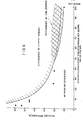
- the catalyst cycle length line is plotted by determining which gauzes will yield efficiencies within the range of this invention by first consulting Figure 6 and drawing a horizontal line corresponding to the minimum efficiency determined from Figure 6 across the appropriate efficiency vs. wire diameter graph, such as Figures 1-3. Then the appropriate recovery gauze cycle lengths "T" for a variety of mesh sizes and wire diameters above this horizontal line are determined using the formula wherein "W” is the weight of each square meter of the recovery gauze sheet and "b" is the amount of platinum lost per ton of ammonia processed. In accordance with the model of the present invention, the rate of platinum recovery is approximately constant at least until the recovery gauze cycle length has been reached, but decreases rapidly thereafter. "W” in general is ⁇ w ⁇ /2.
- ⁇ for a single linen weave gauze can be determined from Figure 4.
- the weight may be calculated in a similar fashion from first principles or if necessary may be determined empirically. If no better data is available from the plant history or the history of a similar plant, "b” may be estimated from Figure 5, presenting loss of platinum per ton of nitrogen processed as a function of nitrogen loading on the catalyst gauze.
- the catalyst cycle length line is drawn connecting the points where the recovery gauze cycle length ",T " coincides with the planned catalyst cycle length of the plant, "Tp". Then a gauze giving an acceptable efficiency and pressure drop is chosen near this line.
- the minimum weight gauze which will both yield an efficiency within the range of this invention and match the planned catalyst cycle length of the plant should be chosen. It is preferred that the gauze sheets used have a weight of less than 2.05 Troy ounces per square foot or more preferably less than 1.9 Troy ounces per square foot.
- the recovery gauze cycle length of the n th gauze is determined by using the formula where " ⁇ i " is the recovery efficiency of the i th recovery gauze sheet and Kn is the weight of the nth gauze.
- gauzes can be added until costs of lost palladium, interest for the cost of the gauze, fabrication and installation over the operating and recovery cycle are not justified by the weight of the platinum recovered. Normally, from about .3 to about .5 grams of palladium will be lost from the recovery gauze for each gram of platinum recovered.
- the first sheet of the pack should be designed as described previously, so that it will have an average recovery efficiency over the catalyst cycle within the range of this invention; i.e., greater than 1 - exp (- 3.45/L .7 ).
- the recovery gauze cycle length for this first gauze sheet will be in the range of from about nine-tenths to eleven-tenths of the planned catalyst gauze cycle length for the plant.
- each succeeding gauze sheet may then be chosen, so that the following relationship is approximately satisfied for each gauze sheet:
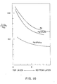
- FIG. 6 is a graph illustrating the average recovery efficiencies obtainable over the catalyst cycle length with the gauzes of the present invention as a function of nitrogen loading, as compared to efficiencies reported in the prior art.
- recovery gauzes almost always contain a major proportion of palladium or gold and minor additions of other alloying elements which improve mechanical properties.
- major proportion of palladium it is meant that the recovery gauze contains at least about 70% palladium by weight.
- the recovery gauzes will contain at least about 80% palladium and more preferably 90%.
- the most preferred recovery gauzes contain at least about 95% palladium by weight.
- the most widely used alloy has been an alloy containing 8 0% palladium and 20% gold. While this alloy has found wide use, alternatives have been sought, since inclusion of gold greatly increases the cost of the gauze.
- Other alloying elements for palladium include other platinum group metals, nickel, manganese, chromium, carbon, boron, and the like.
- Particularly useful palladium alloys include palladium/gold, palladium/platinum, palladium/nickel, palladium/copper, palladium/ruthenium, and palladium/silver.
- gauzes containing a major proportion of gold and a minor proportion of a platinum group metal have been suggested, since it has been reported that gold does not volatilize to the same extent as palladium. The ability of these gold-rich alloys to withdraw platinum seems to be somewhat less than the ability of palladium-rich alloys.
- the mechanical properties of the gold-rich alloys may be improved by adding metals which have a greater affinity for platinum than for oxygen, such as tantalum, niobium, and the like.
- suitable alloying elements include titanium, zirconium, chromium, nickel, manganese, and the like.
- the preferred alloys are palladium/gold and palladium/nickel alloys, particularly alloys containing at least about 80% palladium.
- 95% palladium and 5% nickel is a particularly advantageous alloy for the practice of the present invention, since it is relatively inexpensive, is easily fabricated and upon exposure to the hot platinum-containing effluent, the wires swell and may double in diameter before they are to be removed. In some cases, the diameter of the wires in the gauze may more than double, reaching approximately 2h times their initial diameter. When properly allowed for, this swelling can be particularly advantageous, as the efficiency of the gauze increases as the wires swell. For example, in a plant having a nitrogen loading of 57 tons per square meter per day, a 36 mesh by .0068 in.
- wire diameter gauze with an initial efficiency of about 11% could provide an efficiency of about 14% after the wires swell to .012 in., and over about 18% if the wires reach 2% times their initial diameter,
- a gauze which provided an instantaneous efficiency which was initially outside the range of the present invention can swell to provide an average efficiency in the range of the present invention providing a much higher efficiency than would have been predicted based on its initial configuration.
- a gauze when nickel/palladium gauzes are used, a gauze may be selected such that its recovery efficiency based on its initial configuration is less than 1 - exp (-3.45/L .7 ), but upon swelling, these gauzes provide an average recovery efficiency over the catalyst cycle in excess of that given in Table IA.
- the average recovery efficiencies over the catalyst cycle ( ) correlate best when recovery is predicted based upon the geometric mean of the initial and swelled diameters, but adequate correlation for the 80% Pd:20% Au gauzes can be obtained if recovery is predicted based upon initial diameter, since the effect of swelling seems to be somewhat less pronounced. If it is desired to account for the effect of swelling in a palladium-gold alloy gauze, the geometric mean wire diameter may be estimated by multiplying the initial diameter by 1.1.
- the geometric mean diameter can be estimated satisfactorily by multiplying the initial diameter by a factor in the range of from about 1.4 to 1.6, depending on the location of the gauze in the recovery pack with the higher end of the range being used for the first or second layers in the pack and the lower end for the fifth and sixth layers. See Operating Example 11 for more details.
- Equation 1 can also be used to estimate average efficiencies if geometric mean wire diameters are used and the recovery gauze cycle length is not exceeded.
- Such brief temperature excursions can be caused by even a very brief "spike" in the ammonia inlet concentration.
- I have been able to perforate recovery gauzes in the laboratory reactor by perturbing feed concentrations of around 11% NH 3 in air with a one second spike of about 13% NH 3 when the central portion of the catalyst gauzes was removed from the catalyst-getter pack so that unconverted ammonia impinged upon the getter pack (see Examples 19 and following).
- any other convenient oxicizable fuel may be used for the purpose of heating the gauze uniformly. Impingement of NH 3 upon the getter can also be avoided by using catalyst gauzes with good low temperature ignition characteristics. For example, gauzes with surfaces which are rich in platinum seem to allow lower temperature light off. Typically, these gauzes can be formed by etching rhodium from the surface of a commercial catalyst gauze or using a gauze with a high platinum content for initial layers of the catalyst gauze pack. A few layers of 52 mesh by 0.0040 in. pure platinum gauze in the beginning of the pack will improve the light off characteristics.
- perforation problems can be alleviated by use of gauzes comprising from about 2% to about 12% gold, and at least about 88% palladium if the diameter of the wires in the gauze exceeds about 0.004 in., the initial void fraction of the gauze ranges from about 0.90 to about 0.70 and the mesh exceeds at least about 28 meshes per lineal inch.
- gauzes comprising from about 2% to about 12% gold, and at least about 88% palladium if the diameter of the wires in the gauze exceeds about 0.004 in., the initial void fraction of the gauze ranges from about 0.90 to about 0.70 and the mesh exceeds at least about 28 meshes per lineal inch.
- the void fraction of the gauze should be from about 0.90 to about 0.75, while the wire diameter should be at least about 0.005 in. and the mesh should be at least about 32 meshes per lineal inch. If from about 3 to 6 sheets of recovery gauze are to be used, it is preferred that the void fraction exceed about 0.80. If from six to nine sheets are to be used, it is also preferred that the void fraction exceed about 0.80 but more preferred that it exceeds about 0.85.
- the initial gauzes should preferably range in void fraction from about 0.75 to about 0.80 and the mesh should be from about 40 to about 60 while the wire diameter should be from about 0.004 to about 0.007.
- the later gauzes should range in void fraction from about 0.80 to about 0.88, and the mesh should be from about 32 to about 50 while the wire diameter should be from about 0.005" to abcut 0.009".
- the gold content of the gauze exceed 3% and more preferably be in the range of from about 4% to about 10%.
- Gauzes containing 95% Pd:5% Au are also surprisingly more resistant to melting than gauzes containing either 100% Pd or 95% Pd:5% N i especially if the above limitations on wire diameter, mesh and void fraction are observed.
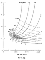
- Figures 11-13 illustrate the variation in pressure drop across a getter sheet with wire diameter at a variety of meshes.
- the illustrated minimum in pressure drop is contrary to what would normally be heuristically expected.
- the preferred low pressure drop recovery gauzes for plants having nitrogen loadings of from about 50 to about 70 tons of ammoniacal nitrogen per square meter per day will have an initial wire diameter at least about 0.004 in., a mesh of at least about 40 and a void fraction of no less than about 0.70 and thus, will be in the region ABCD indicated on Figure 11. More preferred low pressure drop gauzes will have an initial wire diameter of at least about 0.005 in. and thus, will lie in the region EFGH, while the most preferred low pressure drop gauzes will have a wire diameter of at least about 0.006 in.
- preferred low pressure drop recovery gauze will have an initial wire diameter at least about 0.004 in., a mesh of at least about 32 and a void fraction of no less than about 0.75 and thus, will be in the region ABC indicated on Figure 12. More preferred low pressure drop gauzes will have an initial wire diameter of at least about 0.0045 in. and thus, will lie in the region DEFG, while the most preferred low pressure drop' gauzes will have a wire diameter of at least about 0.006 in.
- preferred low pressure drop gauzes will have an initial wire diameter at least about 0.005 in., a mesh of at least about 28 and a void fraction of no less than about 0.80 and thus, will be in the region ABC indicated on Figure 13. More preferred low pressure drop gauzes will have an initial wire diameter of at least about 0.005 in. and thus, will lie in the region DEFG, while the most preferred low pressure drop gauzes will have a wire diameter of at least about 0.006 in.
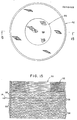
- the recovery gauzes of the present invention may be employed in the form of screens 10 having wires 20 and openings 30.
- the number of mass transfer units (MTU) represented by a single gauze may be determined from the relationship
- a gauze ensemble 20 is placed into reaction chamber 40 ( Figure 10) of a combustion vessel 42.
- This ensemble 20 includes recovery gauze pack 21 and catalyst pack 25 placed adjacent to one another.
- Catalyst pack 25 contains individual sheets 24 of catalyst in the form of nettings or screens stacked one atop the other.
- the catalyst pack is depicted with seven sheets of catalyst, but it is to be understood that the precise number of sheets is not critical and they may be increased or decreased as needed to effect an essentially complete conversion of ammonia to nitrogen oxides.
- One such catalyst consists of 90% platinum/ 5% rhodium/5% palladium, but other platinum-containing catalysts may also be employed with good results.
- Recovery gauze pack 21 contains two sheets of recovery gauze 22 sandwiched between separator screens 23.
- the recovery gauze packs must be of sufficient mechanical strength to withstand the force of the process stream at high reaction temperatures while simultaneously enduring the corrosive effects of the residual ammonia, oxygen and nitrogen oxide products which are formed during the process.
- a recovery gauze is to be designed for a nitric acid plant operating at 900°C., 10% NH 3 and a loading of 15 U. S . tons of nitrogen in ammonia per square meter per day.
- the plant operates on a cycle length of 130 days, at a pressure of 100 p.s.i.g.
- a diagram ( Figure 1) is prepared of the single sheet efficiency of a recovery gauze as a function of mesh size and wire diameter.
- Figure 6 is then consulted, and it is determined that an efficiency in excess of 40 % should be obtainable. It can be seen from Figure 1 that a 50 mesh gauze with wires .0095 in. in diameter would provide a suitable instantaneous efficiency (i).
- a 50 mesh gauze with wires .006 in diameter is prepared from 95% Pd:5% Ni.
- the gauze swells by a factor of about 2.5 to a wire diameter of about .015 in., providing an efficiency (based on the geometric average wire diameter of .0095) in excess of 40%. From Figure 5, it can be estimated that such a plant can be expected to lose about .8 to .9 grams of platinum for each ton of nitrogen converted. Thus, about 12.75 grams of platinum per day are presented to each square meter of gauze which weighs about 916 c/m 2 .
- the first gauze sheet can be expected to remove over 40% of this for a recovery of about 5.1 grams of Pt per day per square meter of gauze, or about 665 g/m 2 over the catalyst cycle.
- the recovery gauze cycle length coincides closely with the planned cycle length of the plant, so this gauze may be used without a heavier, but less efficient gauze upstream of it.
- About .3 to .4 grams of palladium can be expected to be lost for each gram of Pt recovered.
- Three screens are used to achieve an average recovery efficiency of 78%. A successive finer and lighter screen may about be used downstream to recover a portion of the residual platinum, if so desired.
- a gauze is to be designed for a plant similar to that in Design Example 1, except that the loading is 57 tons/m 2- day, and the cycle length is 60 days.
- a plant of this type can be expected to lose between about 1.4 and 1.6 grams of Pt per ton of ammonia converted.
- Figure 6 shows that an efficiency of more than 17% can be obtained. It can be seen from Figure 2 that this can be obtained with a 60 mesh screen having a wire diameter of .006 in. An 80% Pd:20% Au screen having these dimensions is selected. Upon operation, about 85 grams of Pt are presented to each square meter of the screen and about 14.5 grams are collected each day. Six screens are used to provide an overall average recovery efficiency of 67%.
- a gauze is to be designed for a plant having a loading of 100 tons of nitrogen in ammonia per square meter per day, and a cycle length of 60 days. According to Figure 5, a plant of this size can be expected to lose between about 1.7 and 1.9 grams of platinum for each ton of nitrogen converted, while an efficiency in excess of 12% can be obtained. However, if an 80% Pd:20% Au gauze having a mesh of 80 and a wire diameter of .005 in. is used, even though an efficiency of over 15% is obtained, the recovery gauze cycle length is shorter than the catalyst gauze cycle length. Therefore, coarser, heavier gauzes should be inserted upstream of the finer, lighter recovery gauzes after the catalyst gauze. Since an 80 mesh by 0.005 in.
- wire diameter gauze of 80% Pd:20% Au has a recovery gauze cycle length of 60 days with a platinum recovery of 948 g/m 2 , the number of grams of Pt presented to each square meter of the first gauze must be decreased from about 180 grams to about 105.
- 4 coarse gauzes of 50 mesh by .0085 wire diameter should be followed by 4 fine .gauzes of 68 mesh by .006 wire diameter to achieve an overall recovery of 67%.
- a recovery gauze system is to be designed for a nitric acid plant operating at 4.5 atmospheres pressure and a nitrogen loading of 13.2 tons of nitrogen in ammonia per square meter per day over a catalyst gauze cycle length of 150 days.
- the catalyst loss rate is known to be 0.144 g.'of Pt and Rh per ton of nitrogen.
- the production rate of the plant is 330 tons of HNO 3 per day, and the effective area of the reactor is 5.8 square meters.
- the predicted recovery gauze cycle length is only about 130 days, resulting in an average recovery efficiency of the plant cycle length of approximately 46% per gauze or a total of 71% for both gauzes.
- each square meter of the improved gauzes of the present invention recover over 370 additional grams of platinum over each cycle length.
- the feed gas was preheated to a temperature within the range of from about 290-310°C.; during the run the gauze exit temperature was maintained at a relatively constant 930°C.
- the run was conducted over an approximately 146 hour period, and in Operating Examples 7 and 8, the runs were maintained for approximately 292 and 483 hours, respectively; however, it will be appreciated that, in practice, the reaction period may be varied over a wide range.
- the experiments were conducted in operating nitric acid plants.
- a recovery gauze pack consisting of two 80% Pd:19.4% Au:.6% Ru, 80 mesh by .0039 inch wire diameter gauze sheets was placed between three separator screens, as shown in Figure 9, and this ensemble was placed into a reaction chamber below 10 sheets of 90Pt/5Rh/5Pd oxidation catalyst having a weight of 4.6769 g.
- the recovery gauzes had a mesh (N) of 80 and wire diameter (d ) of 0.0031 inches.
- the surface area of each recovery screen (bulk surface area of the wires per unit volume of screen) was 263 in. -1 .
- Feed gas consisting of ammonia and air was forced through the oxidation catalyst and recovery gauze pack as a mixed gas stream under a pressure of 100 p.s.i.g. for a loading of 57 tons of nitrogen per square meter per day.
- the yield of nitrogen oxides (NOx) was about 95%.
- the average recovery efficiency ( ⁇ *) for the Pd/Au recovery gauze pack' was determined from assay data by measuring the Pt gain of each recovery gauze and the Pt loss of the ammonia oxidation catalyst ( i.e., the oxidation gauze pack) as follows:
- the catalyst weighed 4.3951 g., and subsequent assay data showed a Pt loss of 0.4203 g. in the oxidation catalyst.
- the first layer of the recovery gauze pack weighed 0.59E5 g., with a Pt gain of 0.0853 g. Based on this data, the average Pt pick-up efficiency ( ⁇ ') of the first recovery gauze was found to be 20.3%.
- the weight of Pt gained by the first recovery gauze must be taken into account.
- the second layer of the recovery gauze pack weighed 0.5747 g. with a Pt gain of 0.0592 g., and the Pt pick-up efficiency of the second recovery gauze was found to be 17.67%. The average Pt recovery efficiency was found to be 19.00%.
- a recovery gauze pack designed according to the principles of the present invention, consisting of two recovery gauze sheets (95Pd/5Ni) was placed between three separator screens, as depicted in Figure 9, and this ensemble was placed into a reaction chamber of the type shown in Figure 8 below a 90Pt/5Rh/5Pd oxidation catalyst (15 sheets).
- the recovery gauzes were 60 mesh and had wire diameters (d w ) of 0.006 inches.
- the ammonia oxidation catalyst weighed 7.1066 g.
- the separator screens were in the form of a wire mesh gauze constructed from a ferrous alloy.
- the ammonia and air feed was forced through the reaction chamber over a 292 hour period as a mixed gas stream under a pressure of 100 p.s.i.g. for a nitrogen loading of 57 tons/m 2- day.
- the average Pt pick-up efficiency for the Pd/Ni recovery gauzes was determined by measuring the Pt gain of each recovery gauze and the Pt loss for the ammonia oxidation catalyst from assay data.
- the catalyst weighed 6.1783 g., and the subsequent assay data showed a Pt loss of 1.0393 g. in the oxidation catalyst.
- the first layer of the recovery gauze pack weighed 1.0110 g., and recovered 0.2709 g. of platinum, based on the gauze assay data for an average platinum pick-up efficiency ( ) of 26.07%.
- the second layer of the recovery gauze pack weighed 0.9560 g. and recovered of 0.1998 g. of platinum, based on the gauze assay data for a platinum pick-up efficiency of 26.0%.
- the average platinum recovery efficiency was found to be 26.04%, which is an extremely significant improvement over known getters operated under similar reaction conditions.
- Table VI The improvement in Pt recovery efficiency for the 95Pd/5Ni recovery gauzes of Operating Examples 7 and 8 is illustrated by Table VI.
- the data in Table VI demonstrates the advantages of the Pd/Ni recovery gauzes of this invention and the improvement in platinum recovery efficiency for the 95Pd/5Ni recovery gauzes of Examples 7 and 8, when compared against an 80Pd/19.4Au/ 0.6Ru recovery gauze of Examples 3 and 4 having a similar initial MTU.
- a recovery gauze pack consisting of five 80%Pd: 20% Au, 24 mesh by 0.008 inch diameter wire gauze sheets were placed between six separator screens in an arrangement similar to that shown in Figure 9.
- This ensemble was placed immediately downstream of a platinum alloy ammonia oxidation catalyst pack (90Pt/5Rh/5Pd) in a nitric acid plant having a nitrogen loading of 78 tons nitrogen (calculated as ammonia.) per square meter of the effective cross-sectional area of the recovery gauze per day (i.e., 78T(N)/m 2 /d).
- the plant was operated for 77 days, during which the oxidation catalyst lost 205 troy ounces in weight, of which 92% of 188 troy ounces were estimated to be platinum.
- the recovery gauze ensemble was removed, weighed and assayed to determine the amount of platinum recovered. Platinum recovery was found to be 42 troy ounces or approximately 22% of the estimated lost platinum.
- the mass transfer unit (MTU) for a single gauze in the recovery pack was calculated to be 0.05, based on its mesh (24), wire diameter (0.008 inches) and nitrogen loading (78T(N)/m 2 /d).
- the total calculated platinum recovery for the five sheets was 24%, a figure which compares favorably with the observed recovery of 22%.
- a recovery gauze pack was constructed by placing five gauze sheets (manufactured from an alloy of 80Pd/19.4 Au/0.6Ru, having a mesh of 36 and a wire diameter of 0.0071 inches) individually between six separator screens.
- the recovery gauze pack thus constructed was placed into a reactor with a nitrogen loading of 78T(N)/m 2 /d.
- the single gauze mass transfer unit (MTU) was calculated at 0.082, and it was predicted that five sheets of recovery gauze would recover about 34 % of the platinum lost from the oxidation gauze catalyst.
- the recovery gauze pack was installed in the plant immediately downstream of the oxidation gauze pack and the plant was operated for 78 days, during which the oxidation gauze lost 213 troy ounces in weight, of which 92% or 196 troy ounces was estimated to be platinum. At the end of the 78 day cycle, the recovery gauze pack was removed and the quantity of platinum recovered was found to be 35%, based on the recovery gauze pack weight and platinum assay. This figure compares favorably with the predicted recovery of 34%. These data are represented on Figure 7.
- a recovery gauze pack consisting of six 36 mesh and 0.0071 inch diameter wire recovery gauze sheets were individually placed between seven separator screens.
- the recovery gauze sheets were manufactured from an alloy composed of 80 weight percent palladium, 19.4 weight percent gold and 0.6 weight percent ruthenium.
- the recovery gauze was placed immediately downstream of a platinum alloy ammonia oxidation catalyst pack (90Pt/10Rh) in a nitric acid plant having a nitrogen loading of 65 tons (in ammonia) per square meter of reactor cross-sectional area per day, ( i.e., 65T(N)/m 2 /d).
- the plant was operated for 61 days, during which the catalyst pack lost 137 troy ounces in weight, of which 92% or 126 troy ounces were estimated to be platinum.
- the mass transfer unit (MTU) of a single gauze was found to be 0.093, and the predicted total pack recovery for platinum was calculated at 43%. This predicted recovery figure (43%) compared favorably with the actual or observed platinum recovery of 52%. This result is shown on Figure 7.
- a platinum recovery gauze pack consisting of 95% Pd/5% Ni were individually placed between seven separator screens. This pack contained six sheets of platinum recovery gauze, the first three having a mesh of 45 and a wire diameter of 0.0083 inches and the last three having a mesh of 60 and a wire diameter of 0.005 inches. This pack was placed immediately downstream of a 90Pt/5Rh/5Pd alloy ammonia oxidation catalyst gauze pack in a nitric acid plant having a nitrogen throughput of 38 tons (in ammonia) per square meter effective gauze cross-sectional area per day ( i.e., 38T(N)/m 2 /d).
- the furthest upstream of the platinum recovery gauzes was gauze sheet 1, followed by gauze sheets 2, 3, 4, 5 and 6, that is, gauze sheet 6 was located the furthest downstream of all of the gauzes.
- the plant was operated continuously for 71 days during which the ammonia oxidation catalyst pack lost 443 troy ounces in weight, of which 408 troy ounces (92%) were estimated to be platinum.
- the platinum recovery gauze was removed from the plant and disassembled for inspection.
- the recovery gauze wires increased in size over their original diameter, and this increase significantly affected their mass transfer unit values.
- the wire swelling factor (S) for each gauze sheet was determined according to the following equation: and the results of these determinations are set forth in Table VII.
- the total platinum recovery for the gauze pack could be predicted to be 69.8%.
- the total platinum recovery could be predicted to be 83.7%.
- the recovery, properly based on geometric mean of the final and initial diameters of the wires in the recovery gauze, is 76.4%.
- a recovery gauze pack consisting of two gauze sheets (80 Pd/19.6 Au/0.4 Ru) were placed between three separator screens, and this ensemble was placed into a first reaction chamber below a 90 Pt/5 Rh/5 Pd oxidation catalyst (10 sheets).
- the Pd/Au gauzes have a mesh of 36 wires per linear inch (N) and a wire diameter (d ) of 0.0071 inches (N x d : 0.256).
- the oxidation catalyst weighed 4.6963 g., and the recovery gauze pack weighed 5.1737 g. prior to the run.
- each recovery screen that is, the surface area of the wires per unit volume of screen packing, was 117 in 2 /in 3 and 0.555 ft 2 per Troy ounce of recovery gauze.
- the separator screens were in the form of wide mesh gauze constructed from a ferrous alloy.
- a second gauze pack consisting of two recovery screens (80% Pd:20% Au), sandwiched between three separator screens.
- the two chambers were preheated to 300°C. and ammonia and air were channeled therethrough as a mixed gas stream under a pressure of 100 p.s.i.g. at a total flow of 680 SCFH.
- Ammonia constituted 10% of the gaseous mixture representing a throughput of 57 tons nitrogen per square meter per day, that is, 57 t (N 2 )m 2 d.
- the first chamber was maintained at a temperature of 930°C.
- the second chamber was maintained at 890°C.
- the test was run over a 146 hour period, and the yield of nitrogen oxides (NO) was 98.4%.
- the weight recovery efficiency ( ⁇ ') for the Pd/Au gauzes was determined by measuring the weight gain of each recovery gauze pack and the weight loss for the ammonia oxidation catalyst. The difference in weight was then converted to weight recovery efficiency ( ⁇ ') according to the following equation: where n and ⁇ ' are as defined hereinabove, and R is the weight of precious metal recovered by the recovery gauze pack divided by the weight of precious metal in the stream presented to the pack.
- the catalyst weighed 4.3973 g., a loss of 0.2989 g. from its starting weight.
- the recovery gauze pack in the first chamber weighed 5.2350 g., a gain of 0.0623 g. Based on this data, the pick-up efficiency ( ⁇ ') of the recovery gauze pack in the first chamber was found to be 14.6%. In calculating the weight pick-up efficiency of the recovery gauze pack in the second chamber, the weight recovery efficiency of the first chamber must be taken into account.
- palladium/gold recovery gauzes having a mesh size (N) in the range of from about 50-80 and a wire diameter (d ) in the range of from about 0.003 to 0.018 inches, exhibit particularly suitable precious metal recovery properties provided they possess an N x d w of at least about 0.3.
- a preferred embodiment of this invention comprises a recovery gauze ensemble comprised of several such recovery screens sandwiched between several separator screens.
- the following example illustrates the improvement in weight recovery efficiency which can be realized with Pd/Ni recovery gauzes.
- a recovery gauze pack consisting of two recovery gauze sheets (Type Ni-B: 95% Pd/5% Ni) was placed between separator screens and this ensemble was placed into a first reaction chamber below a 90% Pt/5% Rh/5% Pd oxidation catalyst (15 sheets).
- the ammonia oxidation catalyst weighed 7.107 g., and the recovery gauze pack weighed 5.164 g. prior to the run.
- the separator screens were in the form of a wide mesh gauze constructed from a ferrous alloy.
- a second gauze pack also consisting of two recovery screens (Type Ni-A: 95% Pd/5% Ni) sandwiched between three separator screens.
- the recovery gauze pack weighed 4.666 g. prior to the run.
- the two chambers were preheated to 300°C. and ammonia and air were channeled therethrough as a mixed gas stream under a pressure of 100 p.s.i.g. at a total flow of 680 SCFH.
- the first chamber was maintained at a temperature of 930°C. and the second chamber was maintained at 890°C.
- Ammonia constituted 10% of the gaseous mixture, representing a throughput of 57 tons nitrogen per square meter per day, that is, 57 t(N2)/m2d.
- Operating Example 18 illustrates that both nickel- containing alloys and gold-containing alloys are effective in recovering platinum and rhodium lost from ammonia oxidation catalysts, and that the characteristically improved recovery efficiency associated with a high N x d product applies equally to the gold and non-gold-containing alloy recovery gauzes of this invention.
- Example 19 The procedure of Example 19 was repeated except that the ammonia concentration was maintained at a constant 11% and the oxidation pack, which consisted of 15 layers of 90%Pt/10%Rh gauze 52, had a 1 ⁇ 2" diameter hole 50 formed in the centers thereof to simulate two dimensional commercial reactor by-pass conditions and ten layers 56 of 95%Pd/5% Ni getter gauze with a gauze geometry of 60 mesh and 0.0047" wire diameter were placed below the oxidation gauze pack, as shown in Figures 14 and 15.
- the oxidation pack which consisted of 15 layers of 90%Pt/10%Rh gauze 52, had a 1 ⁇ 2" diameter hole 50 formed in the centers thereof to simulate two dimensional commercial reactor by-pass conditions and ten layers 56 of 95%Pd/5% Ni getter gauze with a gauze geometry of 60 mesh and 0.0047" wire diameter were placed below the oxidation gauze pack, as shown in Figures 14 and 15.
- interstitial Kanthal separator screens 58 placed between adjacent getter gauzes 56, were painted with a temperature indicator of Tempilak * (available up to a melting point of 1371°C), in order to detect the maximum temperatures reached in radial and axial * Registered Trade Mark of Big Three Industries, Inc. + Registered Trade Mark of the Kanthal Corporation temperature zones, while thermocouple 54 was embedded between the second and third layers of getter gauze 56 and the ammonia flow was gradually increased up to 13.5%. During the period in which the NH 3 inlet concentration was 13.5%, the gauze exit temperature increased from 910°C to 1210°C, while embedded thermocouple 54 between second and third layers of getter 56 indicated a maximum temperature of 1350°C. After six minutes, the ammonia flow was discontinued and the reactor dismantled. No evidence of gauze melting or perforation was found.
- Tempilak * available up to a melting point of 1371°C
- Examples 19-40 demonstrate the surprisingly increased perforation resistance of the gauzes consisting essentially of 95% Pd and 5% Au.
- Examples 31, 35,. 38, and 40 demonstrate the improved perforation resistance of these gauzes particularly well since the damage to 95% P d:5%Au gauzes was much less than the damage to adjacent gauzes of differing composition but similar geometry.
Landscapes
- Chemical & Material Sciences (AREA)
- Engineering & Computer Science (AREA)
- Organic Chemistry (AREA)
- Materials Engineering (AREA)
- Mechanical Engineering (AREA)
- Metallurgy (AREA)
- Manufacturing & Machinery (AREA)
- Chemical Kinetics & Catalysis (AREA)
- Life Sciences & Earth Sciences (AREA)
- Environmental & Geological Engineering (AREA)
- General Life Sciences & Earth Sciences (AREA)
- Geology (AREA)
- Catalysts (AREA)
- Manufacture And Refinement Of Metals (AREA)
- Respiratory Apparatuses And Protective Means (AREA)
Applications Claiming Priority (2)
| Application Number | Priority Date | Filing Date | Title |
|---|---|---|---|
| US76730785A | 1985-08-19 | 1985-08-19 | |
| US767307 | 1985-08-19 |
Publications (1)
| Publication Number | Publication Date |
|---|---|
| EP0216493A1 true EP0216493A1 (fr) | 1987-04-01 |
Family
ID=25079090
Family Applications (1)
| Application Number | Title | Priority Date | Filing Date |
|---|---|---|---|
| EP19860306362 Withdrawn EP0216493A1 (fr) | 1985-08-19 | 1986-08-18 | Récupération de platine à l'aide de grilles résistant à la perforation |
Country Status (3)
| Country | Link |
|---|---|
| EP (1) | EP0216493A1 (fr) |
| JP (1) | JPS6244536A (fr) |
| ES (1) | ES2000874A6 (fr) |
Cited By (3)
| Publication number | Priority date | Publication date | Assignee | Title |
|---|---|---|---|---|
| EP0519701A1 (fr) * | 1991-06-17 | 1992-12-23 | Johnson Matthey Public Limited Company | Elément ayant une grande surface et une faible perte de pression pour la récupération du platine dans une installation de production d'acide nitrique |
| DE202024101437U1 (de) | 2024-03-22 | 2024-05-08 | Umicore Ag & Co. Kg | Gestrickte Netzpackung für die Ammoniakumsetzung |
| WO2025087895A1 (fr) | 2023-10-23 | 2025-05-01 | Umicore Ag & Co. Kg | Utilisation de mailles en métal noble pour l'oxydation de l'ammoniac |
Families Citing this family (1)
| Publication number | Priority date | Publication date | Assignee | Title |
|---|---|---|---|---|
| BR112019015236B1 (pt) * | 2017-02-20 | 2022-08-30 | Rohm And Haas Company | Material de catalisador de metal, método de fabricação de materiais de catalisador de metal, e, método para melhorar a ignição de reagentes gasosos na superfície de uma tela de catalisador de metal |
Citations (3)
| Publication number | Priority date | Publication date | Assignee | Title |
|---|---|---|---|---|
| US2648393A (en) * | 1949-02-03 | 1953-08-11 | Degussa | Process for the recovery of platinum |
| EP0063450A1 (fr) * | 1981-04-10 | 1982-10-27 | Johnson Matthey Public Limited Company | Récupération des métaux précieux |
| EP0077121A2 (fr) * | 1981-08-12 | 1983-04-20 | Engelhard Corporation | Procédé pour la récupération de platine dans une installation d'acide nitrique |
-
1986
- 1986-08-18 EP EP19860306362 patent/EP0216493A1/fr not_active Withdrawn
- 1986-08-18 ES ES8601166A patent/ES2000874A6/es not_active Expired
- 1986-08-18 JP JP61191810A patent/JPS6244536A/ja active Pending
Patent Citations (3)
| Publication number | Priority date | Publication date | Assignee | Title |
|---|---|---|---|---|
| US2648393A (en) * | 1949-02-03 | 1953-08-11 | Degussa | Process for the recovery of platinum |
| EP0063450A1 (fr) * | 1981-04-10 | 1982-10-27 | Johnson Matthey Public Limited Company | Récupération des métaux précieux |
| EP0077121A2 (fr) * | 1981-08-12 | 1983-04-20 | Engelhard Corporation | Procédé pour la récupération de platine dans une installation d'acide nitrique |
Cited By (4)
| Publication number | Priority date | Publication date | Assignee | Title |
|---|---|---|---|---|
| EP0519701A1 (fr) * | 1991-06-17 | 1992-12-23 | Johnson Matthey Public Limited Company | Elément ayant une grande surface et une faible perte de pression pour la récupération du platine dans une installation de production d'acide nitrique |
| TR25935A (tr) * | 1991-06-17 | 1993-11-01 | Johnson Matthey Inc | ALCAK BASINC DüSMESI,YüKSEK YüZÖLCüMLü PLATINI BIR NITRIK ASITE DAYANIKLI TESISTE ELDE ETME YÖNTEMI |
| WO2025087895A1 (fr) | 2023-10-23 | 2025-05-01 | Umicore Ag & Co. Kg | Utilisation de mailles en métal noble pour l'oxydation de l'ammoniac |
| DE202024101437U1 (de) | 2024-03-22 | 2024-05-08 | Umicore Ag & Co. Kg | Gestrickte Netzpackung für die Ammoniakumsetzung |
Also Published As
| Publication number | Publication date |
|---|---|
| ES2000874A6 (es) | 1988-03-16 |
| JPS6244536A (ja) | 1987-02-26 |
Similar Documents
| Publication | Publication Date | Title |
|---|---|---|
| EP0077121B2 (fr) | Procédé pour la récupération de platine dans une installation d'acide nitrique | |
| US4412859A (en) | Method for recovering platinum in a nitric acid plant | |
| US4497657A (en) | Method for recovering platinum in a nitric acid plant | |
| EP0216493A1 (fr) | Récupération de platine à l'aide de grilles résistant à la perforation | |
| AU2007293761B2 (en) | Method and device for catchment of platinum group metals in a gas stream | |
| Chernyshov et al. | Platinum metals catalytic systems in nitric acid production | |
| US4526614A (en) | Method for recovering platinum in a nitric acid plant | |
| US3873675A (en) | Catalyst and catalyst arrangement for the production of nitric acid | |
| Heck et al. | A new research pilot plant unit for ammonia oxidation processes and some gauze data comparisons for nitric acid process | |
| CA1185955A (fr) | Element foramine pour la separation du platine | |
| Lee et al. | Catalyst deactivation due to transient behavior in nitric acid production | |
| WO2024017928A1 (fr) | Procédé de récupération sélective de pt ou de pd volatil | |
| CA1185954A (fr) | Element foramine et methode pour la separation du platine | |
| EP0519699A1 (fr) | Catalyseur d'oxydation à haute surface spécifique et faible perte de pression, et catalyseur pour la production de l'acide cyanhydrique | |
| GB2037606A (en) | Laminar charge of a catalyst of precious metals for oxidation of ammonia to nitric oxide | |
| EP1838612A1 (fr) | Procede et dispositif pour extraire du monoxyde de carbone d'un flux gazeux contenant de l'hydrogene | |
| US3248344A (en) | Method of activating oxidation catalyst compositions | |
| PL107510B1 (pl) | Katalizator warstwowy z metali szlachetnych do utleniania amoniaku do tlenku azotu | |
| Trumić et al. | Impact of the increased active surface of the platinum catalyst on the total ammonia recovery coefficient | |
| PL107549B1 (pl) | Siatka z metali szlachetnych do odzyskiwania platynowcow a zwlaszcza platyny podczas utleniania amoniaku | |
| Inger et al. | Two-Stage Catalytic Abatement of [N. sub. 2] O Emission in Nitric Acid Plants | |
| Sloan et al. | The New ICI Nitric Acid Plant at Ardeer | |
| du Chatelier | Optimizing catalyst pack design for ammonia oxidation | |
| PL107548B1 (pl) | Siatka z metali szlachetnych do odzyskiwania platynowcow a zwlaszcza platyny w procesie utleniania amoniaku | |
| JPH0834620A (ja) | メタル担体触媒からの貴金属回収方法 |
Legal Events
| Date | Code | Title | Description |
|---|---|---|---|
| PUAI | Public reference made under article 153(3) epc to a published international application that has entered the european phase |
Free format text: ORIGINAL CODE: 0009012 |
|
| AK | Designated contracting states |
Kind code of ref document: A1 Designated state(s): AT BE CH DE FR GB IT LI LU NL SE |
|
| STAA | Information on the status of an ep patent application or granted ep patent |
Free format text: STATUS: THE APPLICATION IS DEEMED TO BE WITHDRAWN |
|
| 18D | Application deemed to be withdrawn |
Effective date: 19871013 |
|
| RIN1 | Information on inventor provided before grant (corrected) |
Inventor name: LEE, HYO C. |