EP0216656A1 - Bandführungsvorrichtung, insbesondere für Walzbandbehandlungseinrichtung - Google Patents
Bandführungsvorrichtung, insbesondere für Walzbandbehandlungseinrichtung Download PDFInfo
- Publication number
- EP0216656A1 EP0216656A1 EP86401782A EP86401782A EP0216656A1 EP 0216656 A1 EP0216656 A1 EP 0216656A1 EP 86401782 A EP86401782 A EP 86401782A EP 86401782 A EP86401782 A EP 86401782A EP 0216656 A1 EP0216656 A1 EP 0216656A1
- Authority
- EP
- European Patent Office
- Prior art keywords
- axis
- frame
- roller
- strip
- fixed frame
- Prior art date
- Legal status (The legal status is an assumption and is not a legal conclusion. Google has not performed a legal analysis and makes no representation as to the accuracy of the status listed.)
- Granted
Links
- 239000000463 material Substances 0.000 title claims abstract description 7
- 239000002184 metal Substances 0.000 title abstract 2
- 238000009434 installation Methods 0.000 title description 4
- 238000011144 upstream manufacturing Methods 0.000 claims abstract description 10
- 230000010355 oscillation Effects 0.000 claims description 15
- 238000000429 assembly Methods 0.000 claims description 5
- 230000000295 complement effect Effects 0.000 claims description 2
- 238000006073 displacement reaction Methods 0.000 description 3
- 230000000694 effects Effects 0.000 description 3
- 230000000712 assembly Effects 0.000 description 2
- 238000010586 diagram Methods 0.000 description 2
- 238000010438 heat treatment Methods 0.000 description 2
- 239000003831 antifriction material Substances 0.000 description 1
- 239000012530 fluid Substances 0.000 description 1
- 238000004519 manufacturing process Methods 0.000 description 1
- 230000035484 reaction time Effects 0.000 description 1
Images



Classifications
-
- B—PERFORMING OPERATIONS; TRANSPORTING
- B65—CONVEYING; PACKING; STORING; HANDLING THIN OR FILAMENTARY MATERIAL
- B65H—HANDLING THIN OR FILAMENTARY MATERIAL, e.g. SHEETS, WEBS, CABLES
- B65H23/00—Registering, tensioning, smoothing or guiding webs
- B65H23/02—Registering, tensioning, smoothing or guiding webs transversely
- B65H23/032—Controlling transverse register of web
- B65H23/038—Controlling transverse register of web by rollers
-
- B—PERFORMING OPERATIONS; TRANSPORTING
- B21—MECHANICAL METAL-WORKING WITHOUT ESSENTIALLY REMOVING MATERIAL; PUNCHING METAL
- B21B—ROLLING OF METAL
- B21B41/00—Guiding, conveying, or accumulating easily-flexible work, e.g. wire, sheet metal bands, in loops or curves; Loop lifters
Definitions
- the present invention relates to guide devices for strip materials, as well as their applications.
- Such a guide device generally comprises a guide roller rotatably mounted about its axis on a movable frame, itself supported by a fixed frame, actuating and holding members being provided for moving and holding the movable frame by compared to the fixed frame.
- the movable frame supporting the guide roller is mounted so as to be able to oscillate about an axis which can be defined as the intersection of a median plane perpendicular to the axis of the roller with a plane containing the upstream strand of the strip. If the strip moves in a vertical plane, the axis of oscillation of the movable frame and consequently of the guide roller, is then found to be vertical, tangent to the roller and contained in the median plane of the latter.
- Such an arrangement has a major drawback which lies in too long a reaction time, since it is necessary to move the movable frame and therefore the guide roller over a large amplitude in order to obtain a correction on the strip and a reminder of the latter in centered position. In addition, the correction has no effect on the upstream strand and the regulation of such a device is difficult in view of this large displacement amplitude.
- the response time of this second device is much shorter, but in return, it has another drawback which consists in an elongation and a deformation of the strip at its edges, this drawback being particularly serious in the case of thin sheets. , that is to say sheets having a thickness less than about 0.4 mm.
- this known device results in limiting the speed of the strips to a value which cannot exceed 25 m / min; still it should be specified that this upper limit is reached only if a manual control is added to the conventional automatic control device.
- the object of this invention is therefore to provide a guide device for elastoplastic web materials, which does not have any of the drawbacks stated above and which, therefore, offers a sufficiently short response time without causing deformation. inadmissible material passing through the device.
- the subject of the invention is a device for guiding a strip of elastoplastic material, comprising a guide roller mounted to rotate about its axis on a movable frame, itself supported by a fixed frame, means of actuation and holding being provided to move and maintain the movable frame relative to the fixed frame, characterized in that the movable frame is mounted on the fixed frame so as to be able to oscillate around an axis contained in a median plane perpendicular to the axis of the roller and forming with one and / or the other strand of the strip an angle of between 5 and 30 °.
- the axis of oscillation is at least approximately tangent to the roller; - The axis of oscillation is tangent to the roller in the vicinity of the upstream strand of the strip; -
- the fixed frame defines an inclined plane on the horizontal and includes support and guide means cooperating with complementary means carried by the movable frame; -
- the support and guide means comprise three sub-assemblies each comprising at least a pair of support surfaces and a couple of cylindrical guide surfaces centered on the axis of oscillation between the two frames; -
- the roller is carried by a frame mounted on an intermediate frame so as to be able to oscillate relative to this intermediate frame around an axis contained in a median plane, perpendicular to the axis of the cylinder, extending perpendicular to the strand the strip and located at a certain distance below the axis of the roller, the intermediate frame itself being mounted on the fixed frame, so as to be able to oscillate around an axis as defined above.
- - Immobilization means
- the guide device shown in the drawings can be placed, for example, in a strip heat treatment oven, or else in an accumulator.
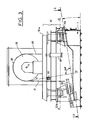
- This device as shown in Fig.1 comprises a fixed frame 1 produced in any suitable manner and which comprises at its upper part a frame 2 delimiting an inclined plane 3 forming with the horizontal an angle ⁇ between 5 and 30 ° and for example around 10 ° in a particular embodiment.
- a movable frame 10 also comprising a frame 11 and provided with two bearing supports 12 between which is rotatably mounted a guide roller 13 carried by a shaft 14.
- This roller is rotatable about its axis XX and can be driven in rotation from a motor 15.
- On the roller 13 passes a strip 20 whose two upstream 21 and downstream 22 strands are here vertical and that it is a question of maintaining in position centered on the roller.
- the movable frame is mounted on the fixed frame so as to be able to oscillate about an axis YY perpendicular to the inclined plane 3 defined by the fixed frame, tangent to the roller 13 on the side of the latter which is attacked by the upstream strand 21 of the strip, and finally contained in the median plane of the roller, perpendicular to the axis XX.
- the means for supporting the movable frame on the fixed frame comprise three bearing assemblies 31, 32, 33 of which two 31.32 are arranged at the upper part of the frame 2 and the other 33 at the part lower of this same frame.
- Each bearing assembly comprises a block 4 secured to the fixed frame and which delimits a support surface 5 and a cylindrical guide surface 6 centered on the axis YY, as well as a foot 40 carried by the movable frame and also delimiting it a bearing surface 41 and a cylindrical guide surface42. These surfaces are made or coated with an appropriate anti-friction material.
- the guide surfaces associated with the lower assembly 33 have a smaller radius than the guide surfaces of the two other bearing assemblies, because they are closer to the axis of oscillation YY.
- the device is supplemented by means for actuating and holding the movable frame relative to the fixed frame.
- actuating means comprise two jacks 50 arranged on two opposite sides of these frames and which are connected to a control device, known per se, and which will not be described in detail here.
- This control device comprises means for supplying the cylinders with hydraulic fluid and a control circuit comprising photocells or other sensors of the position of the strip which, as a function of the position of the latter, ensure the supply jacks so as to move the movable frame in a proper direction to return the strip to its centered position.
- the angular movement between the two extreme positions of the guide roller can be, for example, of the order of 15 ° in a particular application.
- this axis can be slightly offset without significantly modifying the operation of the device.
- the angle which this axis forms with a reference direction which can be the direction of the adjacent strand of the strip to be guided can be chosen in a range between 5 and 30 °, preferably between 7 and 20 °, for the applications considered.
- the invention therefore makes it possible to divide the elongation on the bank by 4.
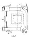
- this device is how, in the embodiment shown in FIGS. 3 to 5, the roller is carried by a frame 10 a mounted with respect to an intermediate frame 10 b in accordance with the teaching of the second prior device described at the top of this thesis, that is to say oscillating around a axis ZZ horizontal and orthogonal to axis XX, and located at a certain distance below this axis XX.
- This intermediate frame 10b is itself mounted on the fixed frame 1 in accordance with the invention.
- Actuating cylinders 51 are provided to move the frame 10 a relative to the frame 10 b , as well as locking devices 52, 53 to selectively secure the frame 10 a to the frame 10 b , or else the frame 10 b to the frame 1.
- the means for guiding the movable frame relative to the fixed frame may be constituted by thrust bearings with balls, needles, a crown or any other suitable means.
Landscapes
- Engineering & Computer Science (AREA)
- Mechanical Engineering (AREA)
- Registering, Tensioning, Guiding Webs, And Rollers Therefor (AREA)
- Winding, Rewinding, Material Storage Devices (AREA)
- Preliminary Treatment Of Fibers (AREA)
- Paper (AREA)
Priority Applications (1)
| Application Number | Priority Date | Filing Date | Title |
|---|---|---|---|
| AT86401782T ATE59317T1 (de) | 1985-09-10 | 1986-08-08 | Bandfuehrungsvorrichtung, insbesondere fuer walzbandbehandlungseinrichtung. |
Applications Claiming Priority (2)
| Application Number | Priority Date | Filing Date | Title |
|---|---|---|---|
| FR8513418A FR2586948B1 (fr) | 1985-09-10 | 1985-09-10 | Dispositif de guidage pour materiau en bande, notamment pour installation de traitement de toles |
| FR8513418 | 1985-09-10 |
Publications (2)
| Publication Number | Publication Date |
|---|---|
| EP0216656A1 true EP0216656A1 (de) | 1987-04-01 |
| EP0216656B1 EP0216656B1 (de) | 1990-12-27 |
Family
ID=9322775
Family Applications (1)
| Application Number | Title | Priority Date | Filing Date |
|---|---|---|---|
| EP86401782A Expired - Lifetime EP0216656B1 (de) | 1985-09-10 | 1986-08-08 | Bandführungsvorrichtung, insbesondere für Walzbandbehandlungseinrichtung |
Country Status (5)
| Country | Link |
|---|---|
| US (1) | US4779782A (de) |
| EP (1) | EP0216656B1 (de) |
| AT (1) | ATE59317T1 (de) |
| DE (1) | DE3676609D1 (de) |
| FR (1) | FR2586948B1 (de) |
Families Citing this family (3)
| Publication number | Priority date | Publication date | Assignee | Title |
|---|---|---|---|---|
| US4963807A (en) * | 1990-02-06 | 1990-10-16 | Zip-Pak Incorporated | Ultrasonic web edge guide circuit |
| DE9306138U1 (de) * | 1993-04-23 | 1994-05-26 | Kronseder, Hermann, 93086 Wörth | Gefäßbehandlungsmaschine |
| JP5040465B2 (ja) * | 2006-08-18 | 2012-10-03 | コニカミノルタホールディングス株式会社 | ベルト搬送装置における蛇行制御手段の調整方法 |
Citations (9)
| Publication number | Priority date | Publication date | Assignee | Title |
|---|---|---|---|---|
| DE843998C (de) * | 1951-03-11 | 1952-07-14 | Vits Elektro G M B H | Drehbarer Abwickelbock fuer Gewebebahnen u. dgl. |
| FR1101433A (fr) * | 1953-12-04 | 1955-10-06 | United States Steel Corp | Magasin-accumulateur |
| US3032248A (en) * | 1959-01-28 | 1962-05-01 | United States Steel Corp | Apparatus for continuously centering a moving strip |
| US3109572A (en) * | 1961-11-14 | 1963-11-05 | Rio Algom Mines Ltd | Apparatus for storing moving strip material |
| FR1577084A (de) * | 1968-08-23 | 1969-08-01 | ||
| DE2025745A1 (de) * | 1969-05-28 | 1970-12-10 | Xerox Corp., Rochester, N.Y. (V.St.A.) | Vorrichtung zur Spurhaltung eines auf einer Rolle bewegten Bandes |
| FR2186940A5 (de) * | 1971-07-28 | 1974-01-11 | Elmeg | |
| DE2428113A1 (de) * | 1974-06-11 | 1976-01-02 | Erhardt & Leimer Kg | Vorrichtung zum kantengeraden aufwickeln von warenbahnen |
| FR2336331A1 (fr) * | 1975-12-22 | 1977-07-22 | Usinor | Dispositif de changement de direction pour materiau en bande |
Family Cites Families (6)
| Publication number | Priority date | Publication date | Assignee | Title |
|---|---|---|---|---|
| US2225276A (en) * | 1938-10-07 | 1940-12-17 | Link Belt Co | Self-aligning idler for belt conveyers |
| US3986650A (en) * | 1974-09-10 | 1976-10-19 | Eastman Kodak Company | Positionally constraining web support |
| JPS5928485B2 (ja) * | 1980-03-22 | 1984-07-13 | のむら産業株式会社 | ベルトの自動蛇行防止装置 |
| JPS5826708A (ja) * | 1981-08-05 | 1983-02-17 | Hiroshi Tsuji | カ−ブベルトコンベヤ |
| US4572417A (en) * | 1984-04-06 | 1986-02-25 | Eastman Kodak Company | Web tracking apparatus |
| US4641770A (en) * | 1985-04-26 | 1987-02-10 | Eastman Kodak Company | Angularly adjustable web-supporting steering roller |
-
1985
- 1985-09-10 FR FR8513418A patent/FR2586948B1/fr not_active Expired
-
1986
- 1986-08-08 DE DE8686401782T patent/DE3676609D1/de not_active Expired - Lifetime
- 1986-08-08 EP EP86401782A patent/EP0216656B1/de not_active Expired - Lifetime
- 1986-08-08 AT AT86401782T patent/ATE59317T1/de not_active IP Right Cessation
- 1986-09-08 US US06/904,972 patent/US4779782A/en not_active Expired - Fee Related
Patent Citations (9)
| Publication number | Priority date | Publication date | Assignee | Title |
|---|---|---|---|---|
| DE843998C (de) * | 1951-03-11 | 1952-07-14 | Vits Elektro G M B H | Drehbarer Abwickelbock fuer Gewebebahnen u. dgl. |
| FR1101433A (fr) * | 1953-12-04 | 1955-10-06 | United States Steel Corp | Magasin-accumulateur |
| US3032248A (en) * | 1959-01-28 | 1962-05-01 | United States Steel Corp | Apparatus for continuously centering a moving strip |
| US3109572A (en) * | 1961-11-14 | 1963-11-05 | Rio Algom Mines Ltd | Apparatus for storing moving strip material |
| FR1577084A (de) * | 1968-08-23 | 1969-08-01 | ||
| DE2025745A1 (de) * | 1969-05-28 | 1970-12-10 | Xerox Corp., Rochester, N.Y. (V.St.A.) | Vorrichtung zur Spurhaltung eines auf einer Rolle bewegten Bandes |
| FR2186940A5 (de) * | 1971-07-28 | 1974-01-11 | Elmeg | |
| DE2428113A1 (de) * | 1974-06-11 | 1976-01-02 | Erhardt & Leimer Kg | Vorrichtung zum kantengeraden aufwickeln von warenbahnen |
| FR2336331A1 (fr) * | 1975-12-22 | 1977-07-22 | Usinor | Dispositif de changement de direction pour materiau en bande |
Also Published As
| Publication number | Publication date |
|---|---|
| FR2586948A1 (fr) | 1987-03-13 |
| FR2586948B1 (fr) | 1989-09-15 |
| EP0216656B1 (de) | 1990-12-27 |
| DE3676609D1 (de) | 1991-02-07 |
| US4779782A (en) | 1988-10-25 |
| ATE59317T1 (de) | 1991-01-15 |
Similar Documents
| Publication | Publication Date | Title |
|---|---|---|
| FR2516409A1 (fr) | Procede de correction d'un materiau lamine | |
| FR2796139A1 (fr) | Procede et dispositif de suppression de la vibration des bandes dans des zones de soufflage de gaz, notamment des zones de refroidissement | |
| FR2802552A1 (fr) | Procede et dispositif de reduction des plis de bande dans une zone de refroidissement rapide de ligne de traitement thermique | |
| LU82855A1 (fr) | Procede,machine et installation pour recuperer les matieres constitutives des batteries d'accumulateurs usees,notamment le plomb | |
| FR2479939A1 (fr) | Engrenages planetaires du type a rouleaux ayant un agencement de prechargement | |
| FR2488819A1 (fr) | Appareil a redresser les tubes d'acier et analogues | |
| EP1163383B1 (de) | Vliesleger | |
| EP0216656B1 (de) | Bandführungsvorrichtung, insbesondere für Walzbandbehandlungseinrichtung | |
| FR2818295A1 (fr) | Dispositif de tirage en continu pour machine a tricoter | |
| FR2574056A1 (fr) | Circuit de chaines a pinces etireuses montees sur galets pour machine a etirer une matiere en bandes | |
| FR2491513A1 (fr) | Dispositif de revetement de feuilles en deplacement | |
| WO2003002435A2 (fr) | Dispositif de transport de pieces pour l'alimentation de machines | |
| FR2781416A1 (fr) | Dispositif de guidage de cahiers dans une plieuse | |
| FR2625460A1 (fr) | Tete de travail pour machine de faconnage d'arbres | |
| FR2714088A1 (fr) | Procédé de contrôle et de réglage de l'égouttage d'une suspension fibreuse sur une table de formation d'une machine à papier et dispositif pour la mise en Óoeuvre du procédé. | |
| FR2668995A1 (fr) | Systeme de renvoi pour chariots transporteurs lies a des rails et ne comportant pas de systeme moteur propre. | |
| FR2575682A1 (fr) | Dispositif pour le dressage de pieces a symetrie de revolution deformables a froid, en particulier des axes, des arbres, des boulons et des pieces analogues | |
| FR2548657A1 (fr) | Procede et dispositif pour la fabrication de verre par flottage | |
| EP3221271B1 (de) | Vorrichtung zur handhabung der kante eines floatglasbandes mit rad mit geneigter achse und installation mit einer derartigen vorrichtung | |
| FR2515696A1 (fr) | Dispositif de condensation du voile de fibres prelevees sur une carde ou analogue | |
| CH646474A5 (en) | Cam box for a weaving machine (loom) | |
| CH353595A (fr) | Mécanisme d'avance réglable | |
| BE679638A (de) | ||
| BE393043A (de) | ||
| FR2880290A1 (fr) | Laminoir comprenant un systeme d'ajustement du serrage et du bombe |
Legal Events
| Date | Code | Title | Description |
|---|---|---|---|
| PUAI | Public reference made under article 153(3) epc to a published international application that has entered the european phase |
Free format text: ORIGINAL CODE: 0009012 |
|
| AK | Designated contracting states |
Kind code of ref document: A1 Designated state(s): AT BE CH DE FR GB IT LI LU NL SE |
|
| 17P | Request for examination filed |
Effective date: 19870619 |
|
| 17Q | First examination report despatched |
Effective date: 19881019 |
|
| RAP1 | Party data changed (applicant data changed or rights of an application transferred) |
Owner name: UGINE ACIERS DE CHATILLON ET GUEUGNON |
|
| ITF | It: translation for a ep patent filed | ||
| GRAA | (expected) grant |
Free format text: ORIGINAL CODE: 0009210 |
|
| AK | Designated contracting states |
Kind code of ref document: B1 Designated state(s): AT BE CH DE FR GB IT LI LU NL SE |
|
| REF | Corresponds to: |
Ref document number: 59317 Country of ref document: AT Date of ref document: 19910115 Kind code of ref document: T |
|
| REF | Corresponds to: |
Ref document number: 3676609 Country of ref document: DE Date of ref document: 19910207 |
|
| GBT | Gb: translation of ep patent filed (gb section 77(6)(a)/1977) | ||
| PLBE | No opposition filed within time limit |
Free format text: ORIGINAL CODE: 0009261 |
|
| STAA | Information on the status of an ep patent application or granted ep patent |
Free format text: STATUS: NO OPPOSITION FILED WITHIN TIME LIMIT |
|
| 26N | No opposition filed | ||
| PGFP | Annual fee paid to national office [announced via postgrant information from national office to epo] |
Ref country code: LU Payment date: 19920715 Year of fee payment: 7 |
|
| PGFP | Annual fee paid to national office [announced via postgrant information from national office to epo] |
Ref country code: DE Payment date: 19920729 Year of fee payment: 7 |
|
| PGFP | Annual fee paid to national office [announced via postgrant information from national office to epo] |
Ref country code: CH Payment date: 19920730 Year of fee payment: 7 |
|
| PGFP | Annual fee paid to national office [announced via postgrant information from national office to epo] |
Ref country code: GB Payment date: 19920731 Year of fee payment: 7 |
|
| PGFP | Annual fee paid to national office [announced via postgrant information from national office to epo] |
Ref country code: AT Payment date: 19920804 Year of fee payment: 7 |
|
| PGFP | Annual fee paid to national office [announced via postgrant information from national office to epo] |
Ref country code: SE Payment date: 19920824 Year of fee payment: 7 |
|
| PGFP | Annual fee paid to national office [announced via postgrant information from national office to epo] |
Ref country code: FR Payment date: 19920828 Year of fee payment: 7 |
|
| ITTA | It: last paid annual fee | ||
| PGFP | Annual fee paid to national office [announced via postgrant information from national office to epo] |
Ref country code: NL Payment date: 19920831 Year of fee payment: 7 |
|
| PGFP | Annual fee paid to national office [announced via postgrant information from national office to epo] |
Ref country code: BE Payment date: 19920909 Year of fee payment: 7 |
|
| EPTA | Lu: last paid annual fee | ||
| PG25 | Lapsed in a contracting state [announced via postgrant information from national office to epo] |
Ref country code: LU Free format text: LAPSE BECAUSE OF NON-PAYMENT OF DUE FEES Effective date: 19930808 Ref country code: GB Effective date: 19930808 Ref country code: AT Effective date: 19930808 |
|
| PG25 | Lapsed in a contracting state [announced via postgrant information from national office to epo] |
Ref country code: SE Effective date: 19930809 |
|
| PG25 | Lapsed in a contracting state [announced via postgrant information from national office to epo] |
Ref country code: LI Effective date: 19930831 Ref country code: CH Effective date: 19930831 Ref country code: BE Effective date: 19930831 |
|
| BERE | Be: lapsed |
Owner name: UGINE ACIERS DE CHATILLON ET GUEUGNON Effective date: 19930831 |
|
| PG25 | Lapsed in a contracting state [announced via postgrant information from national office to epo] |
Ref country code: NL Effective date: 19940301 |
|
| GBPC | Gb: european patent ceased through non-payment of renewal fee |
Effective date: 19930808 |
|
| NLV4 | Nl: lapsed or anulled due to non-payment of the annual fee | ||
| PG25 | Lapsed in a contracting state [announced via postgrant information from national office to epo] |
Ref country code: FR Effective date: 19940429 |
|
| REG | Reference to a national code |
Ref country code: CH Ref legal event code: PL |
|
| PG25 | Lapsed in a contracting state [announced via postgrant information from national office to epo] |
Ref country code: DE Effective date: 19940503 |
|
| REG | Reference to a national code |
Ref country code: FR Ref legal event code: ST |
|
| EUG | Se: european patent has lapsed |
Ref document number: 86401782.7 Effective date: 19940310 |
|
| PG25 | Lapsed in a contracting state [announced via postgrant information from national office to epo] |
Ref country code: IT Free format text: LAPSE BECAUSE OF NON-PAYMENT OF DUE FEES;WARNING: LAPSES OF ITALIAN PATENTS WITH EFFECTIVE DATE BEFORE 2007 MAY HAVE OCCURRED AT ANY TIME BEFORE 2007. THE CORRECT EFFECTIVE DATE MAY BE DIFFERENT FROM THE ONE RECORDED. Effective date: 20050808 |