EP0216733B1 - Modifications d'un moteur auto-synchronisé pour entraînement pas à pas - Google Patents
Modifications d'un moteur auto-synchronisé pour entraînement pas à pas Download PDFInfo
- Publication number
- EP0216733B1 EP0216733B1 EP86830101A EP86830101A EP0216733B1 EP 0216733 B1 EP0216733 B1 EP 0216733B1 EP 86830101 A EP86830101 A EP 86830101A EP 86830101 A EP86830101 A EP 86830101A EP 0216733 B1 EP0216733 B1 EP 0216733B1
- Authority
- EP
- European Patent Office
- Prior art keywords
- motor
- synchronous
- configuration
- statoric
- driven
- Prior art date
- Legal status (The legal status is an assumption and is not a legal conclusion. Google has not performed a legal analysis and makes no representation as to the accuracy of the status listed.)
- Expired - Lifetime
Links
- 230000001360 synchronised effect Effects 0.000 title claims description 21
- 238000012986 modification Methods 0.000 title description 2
- 230000004048 modification Effects 0.000 title description 2
- 230000003247 decreasing effect Effects 0.000 claims description 6
- 230000007423 decrease Effects 0.000 claims description 2
- 230000000903 blocking effect Effects 0.000 claims 1
- 238000010586 diagram Methods 0.000 description 7
- 238000007689 inspection Methods 0.000 description 3
- 230000000694 effects Effects 0.000 description 2
- 238000000034 method Methods 0.000 description 2
- 230000001174 ascending effect Effects 0.000 description 1
- 230000005540 biological transmission Effects 0.000 description 1
- 239000004020 conductor Substances 0.000 description 1
- 238000013500 data storage Methods 0.000 description 1
- 230000005672 electromagnetic field Effects 0.000 description 1
- 238000005516 engineering process Methods 0.000 description 1
- 230000009466 transformation Effects 0.000 description 1
Images


Classifications
-
- H—ELECTRICITY
- H02—GENERATION; CONVERSION OR DISTRIBUTION OF ELECTRIC POWER
- H02P—CONTROL OR REGULATION OF ELECTRIC MOTORS, ELECTRIC GENERATORS OR DYNAMO-ELECTRIC CONVERTERS; CONTROLLING TRANSFORMERS, REACTORS OR CHOKE COILS
- H02P8/00—Arrangements for controlling dynamo-electric motors rotating step by step
- H02P8/42—Arrangements for controlling dynamo-electric motors rotating step by step characterised by non-stepper motors being operated step by step
-
- H—ELECTRICITY
- H02—GENERATION; CONVERSION OR DISTRIBUTION OF ELECTRIC POWER
- H02P—CONTROL OR REGULATION OF ELECTRIC MOTORS, ELECTRIC GENERATORS OR DYNAMO-ELECTRIC CONVERTERS; CONTROLLING TRANSFORMERS, REACTORS OR CHOKE COILS
- H02P6/00—Arrangements for controlling synchronous motors or other dynamo-electric motors using electronic commutation dependent on the rotor position; Electronic commutators therefor
- H02P6/34—Modelling or simulation for control purposes
-
- H—ELECTRICITY
- H02—GENERATION; CONVERSION OR DISTRIBUTION OF ELECTRIC POWER
- H02P—CONTROL OR REGULATION OF ELECTRIC MOTORS, ELECTRIC GENERATORS OR DYNAMO-ELECTRIC CONVERTERS; CONTROLLING TRANSFORMERS, REACTORS OR CHOKE COILS
- H02P8/00—Arrangements for controlling dynamo-electric motors rotating step by step
- H02P8/14—Arrangements for controlling speed or speed and torque
Definitions
- the invention relates to the modifications needed to transform a synchronous motor, as that claimed in the Italian priority document No 3426A/85 available for inspection in the file EP-A-208657, into a motor with two drive modes, i.e. step-by-step and constant running.
- a motor which can turn drive digital data into precise angular rotations (steps) of the motor, while, at the same time, retaining the option of constant deflecting torque drive throughout the 360° rotation angle, corresponding to a full rotation, as in a standard running motor, thus solving one of the main problems of servomotors in the technical applications of automation.
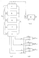
- a logic interface between the micro-data processor and the motor's three-phase inverter.
- the said logic interface nullifies by means of an appropriate control signal from the micro-data processor the stator's field configuration, generated by the rotary commutator and replaces it with one of the stator field configurations stored in the memory of the driving system, selected by the micro-data processor according to the rotor positional data and to the step mode required by the device using it.
- FIG. 3 illustrates the interface logic between the micro-computer and the motor's three phase inverter.
- A indicates the synchronous motor
- B the position sensor
- C the data input interface
- F the EPROM 2716 type programme memory
- F the RAM 2114 type data storage
- G the data transmission interface
- H the system of conductors (BUS) connecting the micro-data processor to the other sections of the micro-computer
- I the command lines through which the micro-data processor controls all the units of the system.
- Fig.3 shows the interface logic design, built with SN74000N integrated circuits, which is inserted in the circuit shown in Fig. 19 of TAB.
- Patent of the priority document No 3426A/85 available for inspection in the file EP-A-208657 by connecting the IC1, IC2 and IC3 outputs of Fig. 19 to the OR inputs 11, 12 and 13 of logic interface (Fig.3), and the AND outputs 17, 18 arid 19 of the same interface logic to the IC5, IC6 and IC7 inputs of Fig. 19.
- the micro-computer system of the step-by-step drive is built around micro-data processor (D) which carries out the programme instructions stored in the EPROM (E).
- the micro-processor on the basis of the rotor position data coming from the sensor position (B), by means of interface (C), seeks in the memory (E) the stator field configuration suitable to the step mode required by the user device.
- the micro-processor sends it, by means of interface (G), to inputs OR 14, 15 and 16 of the interface logic (Fig.3).
- the said logic is the key circuit for the whole step-by-step drive system. It is, in fact, by means of this circuit that the micro-computer replaces the magnetic stator field configuration generated by the rotary commutator (21) constantly present in inputs OR 11, 12 and 13, with a configuration of the stator magnetic field, selected in the memory (E) according to the sensor position (B) available in inputs OR 14, 15 and 16.
- the replacement occurs when the micro-computer disables, by placing at the 0 logic level (0 V.) the command electrode 20 of the said interface logic (FIG.3), the OR gates 2, 4, 6 by means of NOT gate 1, thus nullifying every effect of the rotary commutator (21) on the stator magnetic field configuration.
- the said micro-data processor with the same 0 logic applied to the electrode 20, enables the OR gates 3, 5 and 7, and at the same time transfers to inputs OR 14,15 and 16 to outputs AND 17,18 and 19 the stator magnetic field configuration selected in the memory (E).
- the interface logic Fig. 3 enables the micro-computer to switch the synchronous motor from the first running mode, as running motor, to the second mode, i.e., step-by step motor and vice versa, according to the logic level applied to the command electrode 20 at any given moment or at any given rotor angle.
- the signals generated by the coaxial position sensor (B), referring to the rotor angles of 60°, 120°, 180°, 240°, 300°, and 360° act as step-by-step synchronism impulses, i.e. they act as start and end of the step signals, being 60° the prototype motor's minimum unit step amplitude with a two-pole rotor and a hexa-pole stator.
- the minimum unit step amplitude is halved to 30°, that is, as the number of the motor's poles increases, the minimum unit rotor step amplitude decreases accordingly.
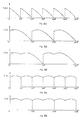
- TAB.2 Figures 4A and 4B, illustrate the prototype motor's rotation at a step of 60° and the decreasing sinusoidal torque.
- Fig.4C illustrates the succession of the six deflecting torque curves of the six 60° steps needed for a complete revolution of the rotor.
- each single torque curve in the said diagram represents only the second ascending part followed by the entire descending part of one of the motor's six sinusoidal torque curves.
- the driving motor system in the case of a triple step 180° large, with the torque of the third part of the same step sinusoidally decreasing, is partially different, as illustrated in Figs. 6A, 6B, 6C and 6D in TAB 2 and TAB.4.
- the first part of amplitude (60°) of the step is achieved by the micro-computer by setting electrode 20 of the interface logic (Fig.3) at logic level 1 (+5 V.) and letting the rotary commutator (21) generate the stator field configuration.
- a step-by-step synchronism impulse signals the micro-computer to reset electrode 20 at 0 logic level (0 V.) and use the stator magnetic field configuration selected in the memory (E), in accordance with position of sensor (B), for the remaining second and third part of amplitude of 120°of the same step.
- the first part of 60° of the triple 180° step is the active part of one of the motor's six sinusoidal torque curves of the motor driven in the first working mode as a running motor.
- Figures 7A 7B and 7C in TAB. 4 illustrate a one step 60° amplitude of the motor rotation at a constant deflecting torque.
- step-by-step synchronism impulse signals the micro-computer to reset the electrode 20 of the said logic at 0 logic level, replacing the stator magnetic field configuration, generated by the rotary commutator (21), with a stator field magnetic configuration selected from memory (E) in accordance with the sensor position (B), required to set to zero the torque, thus locking the motor in the end-of-step position.
- FIG.5 illustrates with a diagram the motor rotation of a step 120° large at a constant torque, achieved through the same method described for the 60° step, with one only difference, i.e., the stator magnetic field configuration which locks the motor at end step (Fig.8D) is activated by a step-by-step synchronism impulse staggered of 120° from the start of the step.
- Figure 8E in TAB.3 shows the motor's torque curve falling sharply to zero at each 120°-step.
- FIG. 5 illustrate how the motor can be stopped in the end of step position, in any given point, e.g. in the two figures, using two different configurations of the statoric magnetic stator field selected in the memory (E) in accordance to the position of sensor (B).
- the torque is zero and the motor, as a consequence, stands still because the two-pole stator field symmetry axis coincides in direction and sense with the symmetry axis of the bipolar rotoric field.
- Fig. 9 illustrate how the motor can be stopped in the end of step position, in any given point, e.g. in the two figures, using two different configurations of the statoric magnetic stator field selected in the memory (E) in accordance to the position of sensor (B).
- the torque is zero and the motor, as a consequence, stands still because the two-pole stator field symmetry axis coincides in direction and sense with the symmetry axis of the bipolar rotoric field.
- statoric hexa-polar field due to the transformation, at the end of the step, of the statoric bipolar field, creates two couples of opposed electro-magnetic fields with equal intensity,which block in a dynamic balance the motor in the point taken as examples, reducing at the same very moment the amplitude of the over swings at the end of the step.
Landscapes
- Engineering & Computer Science (AREA)
- Power Engineering (AREA)
- Control Of Stepping Motors (AREA)
- Shutters For Cameras (AREA)
- Control Of Motors That Do Not Use Commutators (AREA)
- Control Of Electric Motors In General (AREA)
Claims (4)
- Moteur synchrone à courant alternatif, actionné par un inverseur, au moyen d'un capteur de position (B), caractérisé en ce que le moteur synchrone à courant alternatif (A) est actionné, dans son deuxième mode de fonctionnement, comme moteur pas-à-pas au moyen dudit capteur de position (B) au moyen d'un micro-ordinateur (C,D,E,F,G,H,I,) et d'une logique d'interface (Fig. 3), à l'aide de laquelle le micro-ordinateur remplace 1a configuration du champ magnétique à stator généré par un commutateur rotatif (21), avec une configuration du champ, sélectionnée en mémoire (E) en fonction de la position du capteur (B), servant à actionner le moteur synchrone, dans son deuxième mode de fonctionnement, comme moteur à un ou plusieurs pas.
- Moteur synchrone à courant alternatif actionné par un inverseur au moyen d'un capteur de position (B), selon la revendication n° 1, caractérisé en ce que le moteur synchrone à courant alternatif (A) est actionné, dans son deuxième mode de fonctionnement, comme moteur à un ou plusieurs pas, avec couple moteur constant depuis le début jusqu'à la fin du pas, au moyen d'une logique d'interface (Fig. 3), à l'aide de laquelle le micro-ordinateur actionne au début et pendant toute la durée du pas, le moteur synchrone dans son premier mode de fonctionnement, comme moteur de traction, en utilisant la configuration du champ magnétique à stator généré par un commutateur rotatif (21), à la fin du pas, le dit micro-ordinateur remplace au moyen de la même logique d' interface (Fig. 3), ladite configuration du champ magnétique à stator par une configuration du champ sélectionnée en mémoire (E) en fonction de la position du capteur (B), servant à remettre à zéro le couple moteur et ainsi arrêter le moteur à la fin du pas.
- Moteur synchrone à courant alternatif actionné par un inverseur au moyen d'un capteur de position (B), selon les revendications n° 1 et 2, caractérisé en outre en ce que le moteur synchrone à courant alternatif (A) peut être actionné, dans son deuxième mode de fonctionnement, comme moteur à plusieur pas avec couple moteur à valeur constante pendant toute la première partie du pas et décroissant pendant toute la deuxième partie de ce même pas, au moyen d'une logique d'interface (Fig. 3), à l'aide de laquelle le micro-ordinateur actionne au début et pendant toute la première partie du pas le moteur synchrone dans son premier mode de fonctionnement, comme moteur de traction utilisant la configuration du champ magnétique à stator généré par un commutateur rotatif (21), au début de la deuxième partie du pas, le micro-ordinateur remplace, grâce à cette même logique d'interface (Fig. 3), ladite configuration du champ magnétique à stator, par une configuration du champ sélectionnée en mémoire (E) en fonction de la position du capteur (B), servant à actionner le moteur synchrone pendant toute la deuxième partie du même pas avec un couple moteur décroissant de façon sinusoïdale pour se remettre à zéro à la fin du pas.
- Moteur synchrone à courant alternatif actionné par un inverseur, au moyen d'un capteur de position (B), selon les revendications n° 1, 2, et 3, caractérisé en outre en ce que le moteur synchrone à courant alternatif (A), actionné par le micro-ordinateur au moyen de la logique d'interface (Fig. 3), dans son deuxième mode de fonctionnement, comme moteur pas-à-pas, peut être bloqué dans la position de fin de pas, grâce à une configuration du champ magnétique à stator, sélectionnée en mémoire (E), en fonction de la position du capteur (B), caractérisée par un nombre total de pôles magnétiques à stator correspondant au nombre de pôles magnétiques de la configuration d'actionnement pas-à-pas, multiplié par trois (Fig. 10), le champ bipolaire d'actionnement pas-à-pas s'est transformé en un champ hexapolaire de blocage en fin de pas, ladite configuration génère deux couples de forces électro-magnétiques opposées de même intensité, qui bloquent le moteur en équilibre dynamique dans la position de fin de pas.
Priority Applications (1)
| Application Number | Priority Date | Filing Date | Title |
|---|---|---|---|
| AT86830101T ATE81426T1 (de) | 1985-05-03 | 1986-04-30 | Modifikationen eines selbstsynchronisierenden motors fuer schrittschaltantriebe. |
Applications Claiming Priority (2)
| Application Number | Priority Date | Filing Date | Title |
|---|---|---|---|
| IT8503427A IT1214895B (it) | 1985-05-03 | 1985-05-03 | Modificazioni del motore autosincro no per azionarlo passo-passo |
| IT342785 | 1985-05-03 |
Publications (3)
| Publication Number | Publication Date |
|---|---|
| EP0216733A2 EP0216733A2 (fr) | 1987-04-01 |
| EP0216733A3 EP0216733A3 (en) | 1987-09-16 |
| EP0216733B1 true EP0216733B1 (fr) | 1992-10-07 |
Family
ID=11107158
Family Applications (1)
| Application Number | Title | Priority Date | Filing Date |
|---|---|---|---|
| EP86830101A Expired - Lifetime EP0216733B1 (fr) | 1985-05-03 | 1986-04-30 | Modifications d'un moteur auto-synchronisé pour entraînement pas à pas |
Country Status (4)
| Country | Link |
|---|---|
| EP (1) | EP0216733B1 (fr) |
| AT (1) | ATE81426T1 (fr) |
| DE (1) | DE3686929T2 (fr) |
| IT (1) | IT1214895B (fr) |
Families Citing this family (2)
| Publication number | Priority date | Publication date | Assignee | Title |
|---|---|---|---|---|
| FR2633787B1 (fr) * | 1988-06-30 | 1991-05-17 | Crouzet Sa | Circuit de commande en mode pas a pas ou en mode auto-commute d'un moteur |
| DE19747169A1 (de) * | 1997-10-24 | 1999-05-06 | Bosch Gmbh Robert | Regelverfahren zur Drehlagenhaltung eines Elektromotors |
Family Cites Families (1)
| Publication number | Priority date | Publication date | Assignee | Title |
|---|---|---|---|---|
| GB1604121A (en) * | 1977-04-08 | 1981-12-02 | Sony Corp | Dc motors |
-
1985
- 1985-05-03 IT IT8503427A patent/IT1214895B/it active
-
1986
- 1986-04-30 AT AT86830101T patent/ATE81426T1/de not_active IP Right Cessation
- 1986-04-30 EP EP86830101A patent/EP0216733B1/fr not_active Expired - Lifetime
- 1986-04-30 DE DE8686830101T patent/DE3686929T2/de not_active Expired - Fee Related
Also Published As
| Publication number | Publication date |
|---|---|
| EP0216733A3 (en) | 1987-09-16 |
| EP0216733A2 (fr) | 1987-04-01 |
| DE3686929T2 (de) | 1993-04-29 |
| IT1214895B (it) | 1990-01-31 |
| ATE81426T1 (de) | 1992-10-15 |
| DE3686929D1 (de) | 1992-11-12 |
| IT8503427A0 (it) | 1985-05-03 |
Similar Documents
| Publication | Publication Date | Title |
|---|---|---|
| KR100349871B1 (ko) | 회전위치검출기가 붙은 영구자석형 동기전동기의 기동방법 및 전동기 제어장치 | |
| US4641066A (en) | Control apparatus for brushless motor | |
| US4959596A (en) | Switched reluctance motor drive system and laundering apparatus employing same | |
| EP0316077B1 (fr) | Moteur sans balais | |
| US5821708A (en) | Electronically commutated motor control | |
| US4250435A (en) | Clock rate control of electronically commutated motor rotational velocity | |
| US3783357A (en) | Constant speed controlling device for a direct current motor | |
| US4774448A (en) | Reversible variable-speed 2-phase electric motor | |
| EP0735664A2 (fr) | Système de commande de l'angle pour une commande à moteur à réluctance commutée, utilisant une horloge à haute fréquence | |
| US5200675A (en) | Commutation circuit for a brushless d.c. motor | |
| US4454458A (en) | Synchronous drive for brushless DC motor | |
| US6356048B1 (en) | Method and device for controlling electric motors of the brushless direct-current type, particularly for moving the weft winding arm in weft feeders for weaving looms | |
| US4899093A (en) | Circuitry for electronically commutating a direct-current motor | |
| EP0774828A1 (fr) | Commande d'alimentation de phase et méthode de commande de machines à réluctance commutée utilisant de simples capteurs de position angulaire à interpolation d'angle | |
| EP0241867B1 (fr) | Dispositif de régulation de l'accélération et de la décélération se référant aux valeurs de glissement | |
| EP0216733B1 (fr) | Modifications d'un moteur auto-synchronisé pour entraînement pas à pas | |
| CA1184595A (fr) | Entrainement synchro | |
| KR100408056B1 (ko) | 단일 센서 구동용 에스알엠의 운전제어방법 | |
| JP2722750B2 (ja) | ブラシレスモータの駆動装置 | |
| JP2547080B2 (ja) | ブラシレスモータのための正弦波信号発生装置 | |
| JP3114937B2 (ja) | モータ制御装置 | |
| JPH02159993A (ja) | 同期型交流サーボモータ駆動装置の基準電流波形発生回路 | |
| JPS6188784A (ja) | ブラシレスモ−タの制御装置 | |
| JP3243884B2 (ja) | ブラシレスモータ及びその停止方法 | |
| EP0220814B1 (fr) | Dispositif et méthode de stabilisation pour moteur pas à pas |
Legal Events
| Date | Code | Title | Description |
|---|---|---|---|
| PUAI | Public reference made under article 153(3) epc to a published international application that has entered the european phase |
Free format text: ORIGINAL CODE: 0009012 |
|
| AK | Designated contracting states |
Kind code of ref document: A2 Designated state(s): AT BE CH DE FR GB LI LU NL SE |
|
| PUAL | Search report despatched |
Free format text: ORIGINAL CODE: 0009013 |
|
| AK | Designated contracting states |
Kind code of ref document: A3 Designated state(s): AT BE CH DE FR GB LI LU NL SE |
|
| 17P | Request for examination filed |
Effective date: 19880127 |
|
| 17Q | First examination report despatched |
Effective date: 19900308 |
|
| GRAA | (expected) grant |
Free format text: ORIGINAL CODE: 0009210 |
|
| AK | Designated contracting states |
Kind code of ref document: B1 Designated state(s): AT BE CH DE FR GB LI LU NL SE |
|
| REF | Corresponds to: |
Ref document number: 81426 Country of ref document: AT Date of ref document: 19921015 Kind code of ref document: T |
|
| REF | Corresponds to: |
Ref document number: 3686929 Country of ref document: DE Date of ref document: 19921112 |
|
| ET | Fr: translation filed | ||
| PLBE | No opposition filed within time limit |
Free format text: ORIGINAL CODE: 0009261 |
|
| STAA | Information on the status of an ep patent application or granted ep patent |
Free format text: STATUS: NO OPPOSITION FILED WITHIN TIME LIMIT |
|
| 26N | No opposition filed | ||
| EPTA | Lu: last paid annual fee | ||
| EAL | Se: european patent in force in sweden |
Ref document number: 86830101.1 |
|
| PGFP | Annual fee paid to national office [announced via postgrant information from national office to epo] |
Ref country code: GB Payment date: 19990426 Year of fee payment: 14 |
|
| PGFP | Annual fee paid to national office [announced via postgrant information from national office to epo] |
Ref country code: SE Payment date: 19990429 Year of fee payment: 14 Ref country code: NL Payment date: 19990429 Year of fee payment: 14 |
|
| PGFP | Annual fee paid to national office [announced via postgrant information from national office to epo] |
Ref country code: LU Payment date: 19990430 Year of fee payment: 14 Ref country code: FR Payment date: 19990430 Year of fee payment: 14 Ref country code: AT Payment date: 19990430 Year of fee payment: 14 |
|
| PGFP | Annual fee paid to national office [announced via postgrant information from national office to epo] |
Ref country code: BE Payment date: 19990517 Year of fee payment: 14 |
|
| PGFP | Annual fee paid to national office [announced via postgrant information from national office to epo] |
Ref country code: DE Payment date: 19990629 Year of fee payment: 14 |
|
| PGFP | Annual fee paid to national office [announced via postgrant information from national office to epo] |
Ref country code: CH Payment date: 19990707 Year of fee payment: 14 |
|
| PG25 | Lapsed in a contracting state [announced via postgrant information from national office to epo] |
Ref country code: LU Free format text: LAPSE BECAUSE OF NON-PAYMENT OF DUE FEES Effective date: 20000430 Ref country code: LI Free format text: LAPSE BECAUSE OF NON-PAYMENT OF DUE FEES Effective date: 20000430 Ref country code: GB Free format text: LAPSE BECAUSE OF NON-PAYMENT OF DUE FEES Effective date: 20000430 Ref country code: CH Free format text: LAPSE BECAUSE OF NON-PAYMENT OF DUE FEES Effective date: 20000430 Ref country code: BE Free format text: LAPSE BECAUSE OF NON-PAYMENT OF DUE FEES Effective date: 20000430 Ref country code: AT Free format text: LAPSE BECAUSE OF NON-PAYMENT OF DUE FEES Effective date: 20000430 |
|
| PG25 | Lapsed in a contracting state [announced via postgrant information from national office to epo] |
Ref country code: SE Free format text: LAPSE BECAUSE OF NON-PAYMENT OF DUE FEES Effective date: 20000501 |
|
| BERE | Be: lapsed |
Owner name: MERLO CARMELO Effective date: 20000430 |
|
| PG25 | Lapsed in a contracting state [announced via postgrant information from national office to epo] |
Ref country code: NL Free format text: LAPSE BECAUSE OF NON-PAYMENT OF DUE FEES Effective date: 20001101 |
|
| REG | Reference to a national code |
Ref country code: CH Ref legal event code: PL |
|
| GBPC | Gb: european patent ceased through non-payment of renewal fee |
Effective date: 20000430 |
|
| PG25 | Lapsed in a contracting state [announced via postgrant information from national office to epo] |
Ref country code: FR Free format text: LAPSE BECAUSE OF NON-PAYMENT OF DUE FEES Effective date: 20001229 |
|
| NLV4 | Nl: lapsed or anulled due to non-payment of the annual fee |
Effective date: 20001101 |
|
| EUG | Se: european patent has lapsed |
Ref document number: 86830101.1 |
|
| PG25 | Lapsed in a contracting state [announced via postgrant information from national office to epo] |
Ref country code: DE Free format text: LAPSE BECAUSE OF NON-PAYMENT OF DUE FEES Effective date: 20010201 |
|
| REG | Reference to a national code |
Ref country code: FR Ref legal event code: ST |