EP0216752A2 - Véhicule chenillé - Google Patents
Véhicule chenillé Download PDFInfo
- Publication number
- EP0216752A2 EP0216752A2 EP86890260A EP86890260A EP0216752A2 EP 0216752 A2 EP0216752 A2 EP 0216752A2 EP 86890260 A EP86890260 A EP 86890260A EP 86890260 A EP86890260 A EP 86890260A EP 0216752 A2 EP0216752 A2 EP 0216752A2
- Authority
- EP
- European Patent Office
- Prior art keywords
- frame
- elastic
- vehicle according
- caterpillar vehicle
- chassis frame
- Prior art date
- Legal status (The legal status is an assumption and is not a legal conclusion. Google has not performed a legal analysis and makes no representation as to the accuracy of the status listed.)
- Withdrawn
Links
Images

Classifications
-
- B—PERFORMING OPERATIONS; TRANSPORTING
- B62—LAND VEHICLES FOR TRAVELLING OTHERWISE THAN ON RAILS
- B62D—MOTOR VEHICLES; TRAILERS
- B62D55/00—Endless track vehicles
- B62D55/08—Endless track units; Parts thereof
- B62D55/104—Suspension devices for wheels, rollers, bogies or frames
- B62D55/108—Suspension devices for wheels, rollers, bogies or frames with mechanical springs, e.g. torsion bars
-
- B—PERFORMING OPERATIONS; TRANSPORTING
- B62—LAND VEHICLES FOR TRAVELLING OTHERWISE THAN ON RAILS
- B62D—MOTOR VEHICLES; TRAILERS
- B62D55/00—Endless track vehicles
- B62D55/08—Endless track units; Parts thereof
- B62D55/10—Bogies; Frames
Definitions
- the invention relates to a crawler vehicle with a chassis frame on which the wheels or castors are articulated and devices to be carried by the chassis frame, which include the engine, transmission, driver's cab, and possibly a loading area.
- the invention has for its object to eliminate this disadvantage, esp. For snow groomers.
- the devices are combined into a constructional unit by means of a frame and the chassis frame, in particular a torsionally soft construction, is connected to the device frame via several, in particular three, elastic bearings.
- This essentially eliminates the defect mentioned at the outset by separating the chassis frame from the actual device frame and connecting the device frame to the chassis frame via a rubber-elastic three-point bearing.
- This makes it possible to form the chassis frame completely torsionally soft, so that it can follow the unevenness of the terrain which can no longer be absorbed by the springs of the wheels, without substantial torsional forces being introduced into the device frame, which is expediently designed as a rigid construction.
- the device frame is designed as a rigid construction because it carries the engine, transmission, driver's cab and loading area.
- the invention offers the further advantage that the two vehicle elements can be separated with a few screws to be loosened, so that, for example, a winter undercarriage (snow groomer undercarriage) can be replaced with a summer undercarriage (chain undercarriage similar to military armored vehicles).
- the undercarriage frame is designed as a ladder frame, the mutually parallel spars of which are connected by shafts pivotably mounted in the spars, spring rockers or rockers for the carrier wheels of the caterpillars being mounted on the shafts if necessary.
- each shaft is surrounded by a tube in the area between the spars, with one base being anchored to its base by a triangular link consisting of preferably torsion-resistant U-profiles, the Tip area of the wishbone on an elastic, in particular made of rubber, on the other tube, preferably arranged in the center, eg is held by means of a hinge pin.
- This configuration avoids edge pressures in the shaft bearings in the spars.
- the undercarriage frame can be spaced apart from one another in a plane that runs essentially perpendicular to the spars, two rubber bearings, in particular in the form of bearing bushes embedded in rubber, for the engagement of tabs of the equipment frame, and further preferably in the longitudinal center plane of the chassis frame, have a further (third) elastic bearing for the device frame.
- the pin axis runs in a preferred manner parallel to the bars of the lead frame.
- an arrangement is particularly expedient in which the rubber bearings are arranged symmetrically to the longitudinal center plane of the chassis frame.
- a further embodiment of the crawler vehicle according to the invention is characterized in that the further (third) elastic bearing located on the chassis frame is designed for supporting the device frame on a torsionally elastic bracket mounted on a rung of the lead frame.
- the console enables a particularly favorable option for the Creation of the support for the device frame. Hiebei it proves to be advantageous if the console has a substantially horizontal support surface for a flange attached to the device frame, whereby for the connection, if necessary, the support surface and the flange are provided through screws.
- a constructive simplification results if the console has a bearing eye into which the elastic mounting (rubber bushing) engages, on which the tip region of the triangular link of the vehicle frame is anchored.
- the means provided for the wishbone for its elastic mounting serve at the same time also for the elastic mounting of the device frame with regard to a bearing point of the device frame.
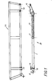
- the vehicle frame 28 is designed as a lead frame which consists of two bars 1 arranged parallel to one another, between which rungs are arranged.
- the rungs can have shafts 5, 9 which are pivotally received in the bars 1 in bearings 6, 10 and are surrounded by tubes 2, 3 in the area between the bars 1.
- the shaft 9 carries a spring rocker 12 to resiliently support a chain wheel 23.
- the shaft 5 carries wheel rockers 7 at its ends.
- a torsion-soft U-profile is provided as the third rung 19, which is screwed to brackets 18 which are fastened to the bars 1.
- the spars 1 can be designed as molded tubes so that they can accommodate insert parts 24, to which a tensioning axis 17 can be fastened for tensioning the caterpillars.
- a triangular link 13 is attached to the tube 2, which is connected via an articulation pin 25 in the area of its tip to an elastic, in particular rubber bearing 14.
- the bearing 14 can be designed as a rubber bushing enclosing the tube 3 and fixed to the tube.
- the struts of the wishbone 13 are also formed by torsionally soft U-profiles. A torsional stress occurring about the longitudinal axis of the chassis frame 28 leads to rotary movements in the joints of the rungs without the stresses that are usual with rigid connections occurring.
- the frame 28 is assembled in such a way that the spars 1 are pushed onto the rungs, namely the shafts 5, 9 provided with the tubes 2, 3, the rocker 12 also being threaded.
- the carrier 19 is connected to the tabs 18.
- the undercarriage frame 28 has two rubber bearings 16 arranged symmetrically to its longitudinal center plane, which have bearing bushes embedded in rubber for receiving bolts which pass through tabs 21 of the device frame 20.
- a third, elastic bearing for the device frame 20 which is formed on a bracket 15 mounted in a torsionally elastic manner on a rung of the lead frame.
- the console 15 is provided with a horizontally oriented support 4 for a flange 22 of the device frame 20.
- the bearing surface 4 and the flange 22 can be connected by screws, the centers of the bores for receiving the screws on the surface 4 being indicated by crosses in FIG. 2.
- the bracket 15 has a bearing eye 27, which is pushed over the elastic, formed by a rubber bushing 14 for the tip region of the wishbone 13.
- the tabs 21 of the device frame 20 are connected to the rubber bearings 16 of the chassis frame 28, which are fastened to the rung 19, by means of bolts 26.
- the flange 22 is with the bracket 15, which forms a bearing with the rubber element 14, screwed.
- An elastic three-point bearing is formed by the rubber elements 14 and 16, on which the device frame 20, which is designed as a framework and is therefore rigid, is mounted.
Landscapes
- Engineering & Computer Science (AREA)
- Chemical & Material Sciences (AREA)
- Combustion & Propulsion (AREA)
- Transportation (AREA)
- Mechanical Engineering (AREA)
- Body Structure For Vehicles (AREA)
- Photoreceptors In Electrophotography (AREA)
- Optical Recording Or Reproduction (AREA)
- Prostheses (AREA)
- Motor Power Transmission Devices (AREA)
- Arrangement Or Mounting Of Control Devices For Change-Speed Gearing (AREA)
Applications Claiming Priority (2)
| Application Number | Priority Date | Filing Date | Title |
|---|---|---|---|
| AT0277485A ATA277485A (de) | 1985-09-23 | 1985-09-23 | Raupenfahrzeug |
| AT2774/85 | 1985-09-23 |
Publications (2)
| Publication Number | Publication Date |
|---|---|
| EP0216752A2 true EP0216752A2 (fr) | 1987-04-01 |
| EP0216752A3 EP0216752A3 (fr) | 1988-06-01 |
Family
ID=3540084
Family Applications (1)
| Application Number | Title | Priority Date | Filing Date |
|---|---|---|---|
| EP86890260A Withdrawn EP0216752A3 (fr) | 1985-09-23 | 1986-09-19 | Véhicule chenillé |
Country Status (6)
| Country | Link |
|---|---|
| US (1) | US4739849A (fr) |
| EP (1) | EP0216752A3 (fr) |
| JP (1) | JPS6285772A (fr) |
| AT (1) | ATA277485A (fr) |
| FI (1) | FI863808L (fr) |
| NO (1) | NO863784L (fr) |
Families Citing this family (1)
| Publication number | Priority date | Publication date | Assignee | Title |
|---|---|---|---|---|
| FI121111B (fi) * | 2007-09-25 | 2010-07-15 | Ponsse Oyj | Sovitelma metsäkoneessa ja metsäkone |
Family Cites Families (7)
| Publication number | Priority date | Publication date | Assignee | Title |
|---|---|---|---|---|
| US2604176A (en) * | 1948-10-25 | 1952-07-22 | Deere & Co | Tractor frame structure |
| FR1169351A (fr) * | 1959-02-18 | 1958-12-26 | Lorraine Anciens Ets Dietrich | Véhicule, en particulier véhicule de police ou militaire |
| DE1278848B (de) * | 1962-10-16 | 1968-09-26 | Soc D Forges Et Ateliers Du Cr | Zumindest zu einem Teil von einem Luftkissen getragenes Landfahrzeug mit Stuetz- oder Antriebsraupen |
| US3446303A (en) * | 1966-06-22 | 1969-05-27 | Outboard Marine Corp | Endless track vehicle |
| US4226293A (en) * | 1979-03-16 | 1980-10-07 | Miller W. Corporation | Track-laying vehicle with improved suspension |
| JPS5751171Y2 (fr) * | 1979-09-05 | 1982-11-08 | ||
| SE425557B (sv) * | 1981-02-17 | 1982-10-11 | Skega Ab | For banddrivna fordon avsett bandaggregat |
-
1985
- 1985-09-23 AT AT0277485A patent/ATA277485A/de unknown
-
1986
- 1986-09-18 JP JP61218285A patent/JPS6285772A/ja active Pending
- 1986-09-19 EP EP86890260A patent/EP0216752A3/fr not_active Withdrawn
- 1986-09-22 FI FI863808A patent/FI863808L/fi not_active IP Right Cessation
- 1986-09-23 US US06/910,891 patent/US4739849A/en not_active Expired - Fee Related
- 1986-09-23 NO NO863784A patent/NO863784L/no unknown
Also Published As
| Publication number | Publication date |
|---|---|
| FI863808A0 (fi) | 1986-09-22 |
| NO863784L (no) | 1987-03-24 |
| FI863808A7 (fi) | 1987-03-24 |
| US4739849A (en) | 1988-04-26 |
| ATA277485A (de) | 1989-12-15 |
| EP0216752A3 (fr) | 1988-06-01 |
| JPS6285772A (ja) | 1987-04-20 |
| NO863784D0 (no) | 1986-09-23 |
| FI863808L (fi) | 1987-03-24 |
Similar Documents
| Publication | Publication Date | Title |
|---|---|---|
| DE938892C (de) | Hinterradaufhaengung fuer Kraftfahrzeuge mit starrer Hinterachsbruecke | |
| DE1168775B (de) | Fahrgestell fuer mehrachsige, insbesondere dreiachsige Fahrzeuge | |
| EP0985336A2 (fr) | Machine agricole autonome de récolte | |
| EP0680869A2 (fr) | Mécanisme de roulement à chenilles pour une moissonneuse | |
| DE2716372C2 (de) | Hydraulikbagger oder dergleichen mit einer Fahrerkabine | |
| DE2349272A1 (de) | Vorderradaufhaengung fuer kraftfahrzeuge | |
| EP3180202B1 (fr) | Dispositif de suspension d'un essieu d'un véhicule | |
| EP1840018A2 (fr) | Chariot à chenilles | |
| DE69426991T2 (de) | Längsarmaufhängung | |
| DE1455887C2 (de) | Radaufhängung für ein Fahrzeug | |
| DE3725920A1 (de) | Fahrgestell | |
| DD207068A3 (de) | Fahrgestell fuer selbstfahrende arbeitsmaschinen | |
| DE2445629A1 (de) | An einem fahrzeug um eine horizontale achse eines gelenks schwenkbar angeordnete fahrerkabine | |
| DE102009016935A1 (de) | Querträger für Kraftfahrzeuge | |
| DE2820476A1 (de) | Automobilkran, rollkran und verfahren zu deren herstellung | |
| DE820696C (de) | Nach Zellenbauweise hergestelltes Kraftfahrzeug | |
| DE2518711A1 (de) | Raupenfahrzeuggestell | |
| DE3707155C2 (fr) | ||
| DE102004011934B4 (de) | Vorderachseinheit für ein Spielfahrzeug | |
| DE2216307A1 (de) | Spurbreitenveraenderbares gleiskettenfahrzeug | |
| CH340141A (de) | Motorfahrzeug mit mindestens drei Rädern | |
| DE3346708C2 (fr) | ||
| DE1005851B (de) | Raupenfahrzeug | |
| DE951131C (de) | Achsaufhaengung fuer Fahrzeuge, insbesondere Kraftfahrzeuge, mit Fuehrung der Achse durch in Laengsrichtung des Fahrzeuges schwingende Lenkervierecke | |
| DE916260C (de) | Vorrichtung zur Regelung der Federspannung von Kraftfahrzeugfederungen |
Legal Events
| Date | Code | Title | Description |
|---|---|---|---|
| PUAI | Public reference made under article 153(3) epc to a published international application that has entered the european phase |
Free format text: ORIGINAL CODE: 0009012 |
|
| AK | Designated contracting states |
Kind code of ref document: A2 Designated state(s): CH DE FR IT LI SE |
|
| PUAL | Search report despatched |
Free format text: ORIGINAL CODE: 0009013 |
|
| AK | Designated contracting states |
Kind code of ref document: A3 Designated state(s): CH DE FR IT LI SE |
|
| STAA | Information on the status of an ep patent application or granted ep patent |
Free format text: STATUS: THE APPLICATION IS DEEMED TO BE WITHDRAWN |
|
| 18D | Application deemed to be withdrawn |
Effective date: 19881003 |
|
| RIN1 | Information on inventor provided before grant (corrected) |
Inventor name: RANNER, DIETRICH, DIPL.-ING. |