EP0217128A1 - Ensemble moto-pompe à palettes sans fuites extérieures d'huile - Google Patents
Ensemble moto-pompe à palettes sans fuites extérieures d'huile Download PDFInfo
- Publication number
- EP0217128A1 EP0217128A1 EP86111795A EP86111795A EP0217128A1 EP 0217128 A1 EP0217128 A1 EP 0217128A1 EP 86111795 A EP86111795 A EP 86111795A EP 86111795 A EP86111795 A EP 86111795A EP 0217128 A1 EP0217128 A1 EP 0217128A1
- Authority
- EP
- European Patent Office
- Prior art keywords
- pump
- motor
- rotor
- stator
- oil
- Prior art date
- Legal status (The legal status is an assumption and is not a legal conclusion. Google has not performed a legal analysis and makes no representation as to the accuracy of the status listed.)
- Granted
Links
- 239000000696 magnetic material Substances 0.000 claims abstract description 4
- 239000002184 metal Substances 0.000 claims 1
- 239000003921 oil Substances 0.000 description 21
- PXGOKWXKJXAPGV-UHFFFAOYSA-N Fluorine Chemical compound FF PXGOKWXKJXAPGV-UHFFFAOYSA-N 0.000 description 2
- 230000008878 coupling Effects 0.000 description 2
- 238000010168 coupling process Methods 0.000 description 2
- 238000005859 coupling reaction Methods 0.000 description 2
- 231100000331 toxic Toxicity 0.000 description 2
- 230000002588 toxic effect Effects 0.000 description 2
- KZBUYRJDOAKODT-UHFFFAOYSA-N Chlorine Chemical compound ClCl KZBUYRJDOAKODT-UHFFFAOYSA-N 0.000 description 1
- 241000447437 Gerreidae Species 0.000 description 1
- 241000555745 Sciuridae Species 0.000 description 1
- 238000009825 accumulation Methods 0.000 description 1
- 150000001805 chlorine compounds Chemical class 0.000 description 1
- 238000001816 cooling Methods 0.000 description 1
- 229910052731 fluorine Inorganic materials 0.000 description 1
- 239000011737 fluorine Substances 0.000 description 1
- 239000010687 lubricating oil Substances 0.000 description 1
- 238000012423 maintenance Methods 0.000 description 1
- 238000000034 method Methods 0.000 description 1
- 230000003068 static effect Effects 0.000 description 1
- 238000004804 winding Methods 0.000 description 1
Images


Classifications
-
- F—MECHANICAL ENGINEERING; LIGHTING; HEATING; WEAPONS; BLASTING
- F04—POSITIVE - DISPLACEMENT MACHINES FOR LIQUIDS; PUMPS FOR LIQUIDS OR ELASTIC FLUIDS
- F04C—ROTARY-PISTON, OR OSCILLATING-PISTON, POSITIVE-DISPLACEMENT MACHINES FOR LIQUIDS; ROTARY-PISTON, OR OSCILLATING-PISTON, POSITIVE-DISPLACEMENT PUMPS
- F04C23/00—Combinations of two or more pumps, each being of rotary-piston or oscillating-piston type, specially adapted for elastic fluids; Pumping installations specially adapted for elastic fluids; Multi-stage pumps specially adapted for elastic fluids
-
- F—MECHANICAL ENGINEERING; LIGHTING; HEATING; WEAPONS; BLASTING
- F04—POSITIVE - DISPLACEMENT MACHINES FOR LIQUIDS; PUMPS FOR LIQUIDS OR ELASTIC FLUIDS
- F04C—ROTARY-PISTON, OR OSCILLATING-PISTON, POSITIVE-DISPLACEMENT MACHINES FOR LIQUIDS; ROTARY-PISTON, OR OSCILLATING-PISTON, POSITIVE-DISPLACEMENT PUMPS
- F04C29/00—Component parts, details or accessories of pumps or pumping installations, not provided for in groups F04C18/00 - F04C28/00
- F04C29/0042—Driving elements, brakes, couplings, transmissions specially adapted for pumps
- F04C29/005—Means for transmitting movement from the prime mover to driven parts of the pump, e.g. clutches, couplings, transmissions
Definitions
- the present invention relates to a vane motor pump group without external oil leaks.
- the vane vacuum pump associated with. an oil tank, is driven by an electric motor.
- Figure.1 shows an axial section of a vane pump and its drive motor, according to the prior art.
- Figure 2 is a sectional view along line I-I of Figure 1.
- the rotor 4 of the pump carries vanes such as 5.
- the gas to be pumped is introduced through a suction orifice 7 and escapes through valves such as 8.
- the rotor is provided with a rotating shaft in flange bearings.
- the bearings 11 and 12 are smooth and they are lubricated by the oil in which the pump is immersed.
- This oil is contained in a cover 13 provided with a level indicator 14 and a drain orifice 15.
- the oil pump and the oil filter usually fitted to the pump have not been represented.
- the pump is rotated by a motor 20 having a shaft 21, and a flange 22 for its attachment to the flange 3 of the pump.
- the shaft 21 of the motor and the shaft 10 of the pump rotor are connected by an elastic coupling sleeve 23, 24 which can serve as a fan for cooling the pump.
- a lip seal 32, on the coupling sleeve side, is intended to prevent large leaks of lubricating oil from the plain bearing.
- the oil then flows outwardly to the pump and is collected in the base 34 of the pump.
- An object of the present invention is to provide a vane motor pump group having no oil leakage outside.
- the subject of the invention is a vane motor pump group comprising a vane pump comprising a rotor, provided with vanes and extended by a shaft and a stator, the rotor-stator assembly being disposed in a tank partially filled with oil, l rotating shaft in bearings lubricated by said oil and provided with seals, said pump being driven in rotation by an electric motor comprising a rotor provided with a shaft and a stator, characterized in that the shafts of the motor rotors and of the pump are secured and that between the stator and the rotor of the motor is disposed a casing of closed non-magnetic material,. on the side opposite the pump, by a bottom and coming from the other side, in sealed support on a flange of the motor, integral with the pump.
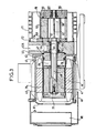
- the motor-pump unit of the invention (see FIG. 3) comprises a frame 40, common to the pump and to the drive motor.
- the bore 40A constitutes the suction pipe of the pump.
- the motor comprises a flange 41 fixed to the frame by bolts 42. A seal is ensured between the flange 41 and the frame by an O-ring 43.
- the motor comprises a stator made up of windings such as 44 arranged in a carcass 45 fixed to the flange by tie rods such than 46.
- the motor also includes a rotor 47 with a squirrel cage, keyed and bolted to a shaft 48.
- the pump comprises a rotor 50, having a shaft 51 and vanes 52, and a stator 53.
- the shaft 51 of the pump rotor 50 and the shaft 48 of the rotor 47 of the motor are produced in the same part.
- the stator of the pump is placed between two flanges 54 and 55.
- O-rings 56 and 57 ensure the seal between the frame 40 and the flange 54.
- O-rings 58 and 59 ensure the seal between the stator and the flanges 54 and 55 respectively.
- the shaft 51 rotates in bearings 61 and 62 respectively of the frame 40 and the flange 55. These bearings are lubricated by the pump oil.
- Lip seals 63 and 64 surround the bearing 61.
- Oil is contained in a finned tank 71 connected to the frame 40 by means of a flat seal 72.
- the shafts 48 of the motor and 51 of the pump rotor are secured, and preferably welded so as to constitute only one shaft.
- a jacket 75 made of non-magnetic material, is arranged in the air gap separating the stator 44 and the rotor 47 of the electric motor.
- This shirt is supported at one end on a step of the flange 41 by an O-ring 76.
- This shirt is closed at the other ends by a flat bottom 77.
- the oil which leaks possibly through the lip seal 63 remains inside the jacket 75 and cannot exit outside.
- the group can be completed by an independent fan 80 fixed to a flange 81, itself fixed to the motor by the tie rods 46.
- the primary pumps of the prior art can be easily converted into motor-pump groups according to the invention because the entire vane pump part with the oil tank remains identical.
Landscapes
- Engineering & Computer Science (AREA)
- Mechanical Engineering (AREA)
- General Engineering & Computer Science (AREA)
- Applications Or Details Of Rotary Compressors (AREA)
- Rotary Pumps (AREA)
- Details And Applications Of Rotary Liquid Pumps (AREA)
- Lubrication Of Internal Combustion Engines (AREA)
- Compressor (AREA)
Abstract
Description
- La présente invention est relative à un groupe moto-pompe à palettes sans fuites extérieures d'huile.
- Dans la technique actuelle, la pompe à vide à palettes, associée à . un réservoir d'huile, est entraînée par un moteur électrique.
- La figure.1 représente une coupe axiale d'une pompe à palettes et de son moteur d'entraînement, selon l'art connu.
- La figure 2 est une vue en coupe selon la ligne I-I de la figure 1.
- Dans les figures 1 et 2, on peut distinguer le stator de la pompe référencé 1 et encadré par des flasques 2 et 3.
- Le rotor 4 de la pompe porte des palettes telles que 5. Le gaz à pomper est introduit par un orifice d'aspiration 7 et s'échappe à travers des soupapes telles que 8.
- Le rotor est muni d'un arbre tournant dans des paliers des flasques. Les paliers 11 et 12 sont lisses et ils sont lubrifiés par l'huile dans laquelle la pompe baigne. Cette huile est contenue dans un capot 13 muni d'un témoin de niveau 14 et d'un orifice de vidange 15. Pour la clarté de l'exposé, la pompe à huile et le filtre à huile équipant habituellement la pompe n'ont pas été représenté.
- - La pompe est entraînée en rotation par un moteur 20 ayant un arbre 21, et un flasque 22 pour sa fixation au flasque 3 de la pompe. L'arbre 21 du moteur et l'arbre 10 du rotor de la pompe sont reliés par un manchon d'accouplement élastique 23, 24 pouvant servir de ventilateur pour le refroidissement de la pompe.
- Un joint à lèvre 31, côté pompe, arrête les fuites d'air entre l'atmosphère et l'aspiration de la pompe.
- Un joint à lèvre 32, côté manchon d'accouplement, est destiné à empêcher les grosses fuites d'huile de graissage du palier lisse.
- Cependant, l'étanchéité dynamique est imparfaite et le joint à lèvre 32 ne peut arrêter les petites fuites d'huile entre l'arbre et la lèvre.
- L'huile coule alors extérieurement à la pompe et est recueillie dans le socle 34 de la pompe.
- Les fuites d'huile sont indésirables pour deux raisons :
- - dans beaucoup d'applications, la pompe aspire des produits toxiques (par exemple des composés du fluor ou du chlore). Ces produits sont mélangés ou dissous dans l'huile et, ainsi, toute fuite d'huile chargée du produit toxique, si minime soit-elle, est à prohiber. La moindre fuite dans une. salle blanche entraine un déclassement immédiat de celle-ci.
- - d'autre part, l'huile synthétique utilisée dans la pompe pour certaines applications est un produit très cher qu'il est donc impératif de ne pas perdre.
- Un but de la présente invention est de réaliser un groupe moto-pompe à palettes n'ayant aucune fuite d'huile à l'extérieur.
- L'invention a pour objet groupe moto-pompe à palettes comprenant une pompe à palettes comprenant un rotor, muni de palettes et prolongé par un arbre et un stator l'ensemble rotor-stator étant disposé dans une cuve remplie partiellement d'huile, l'arbre tournant dans des paliers graissés par ladite huile et munis de joints d'étanchéité, ladite pompe étant entraînée en rotation par un moteur électrique comprenant un rotor muni d'un arbre et un stator, caractérisé en ce que les arbres des rotors du moteur et de la pompe sont solidarisés et qu'entre le stator et le rotor du moteur est disposé une enveloppe en matériau amagnétique fermé, . du côté opposé à la pompe, par un fond et venant de l'autre côté, en appui étanche sur un flasque du moteur, solidaire de la pompe.
- L'invention est explicitée par la description donnée ci-après d'un mode préféré de réalisation de l'invention, en référence au dessin annexé dans lequel :
- - la figure 1 est une vue en coupe axiale d'une pompe selon l'art connu
- - la figure 2 est une vue en coupe selon la ligne I-I de la figure 1
- - la figure 3 est une vue en coupe axiale d'un groupe moto-pompe selon l'invention.
- Le groupe moto-pompe de l'invention (voir figure 3) comprend un bâti 40, commun à la pompe et au moteur d'entraînement. L'alésage 40A constitue le conduit d'aspiration de la pompe.
- Le moteur comprend un flasque 41 fixé au bâti par des boulons 42. Une étanchéité est assurée entre le flasque 41 et le bâti par un joint torique 43.
- Le moteur comprend un stator constitué de bobinages tels que 44 disposés dans une carcasse 45 fixée au flasque par des tirants tels que 46.
- Le moteur comprend également un rotor 47 à cage d'écureuil, claveté et boulonné sur un arbre 48.
- La pompe comprend un rotor 50, ayant un arbre 51 et des palettes 52, et un stator 53. L'arbre 51 du rotor de pompe 50 et l'arbre 48 du rotor 47 du moteur sont réalisés dans la même pièce.
- Le stator de la pompe est disposé entre deux flasques 54 et 55. Des joints toriques 56 et 57 assurent l'étanchéité entre le bâti 40 et le flasque 54.
- De même des joints toriques 58 et 59 assurent l'étanchéité entre le stator et les flasques 54 et 55 respectivement.
- L'arbre 51 tourne dans des paliers 61 et 62 respectivement du bâti 40 et du flasque 55. Ces paliers sont lubrifiés par l'huile de la pompe.
- Des joints à lèvre 63 et 64 encadrent le palier 61.
- De l'huile est contenue dans une cuve à ailettes 71 reliée au bâti 40 par l'intermédiaire d'un joint d'étanchéité plat 72.
- Elle atteint un niveau 70 supérieur à la partie haute du stator 53.
- Selon une caractéristique de l'invention les arbres 48 du moteur et 51 du rotor de pompe sont solidarisés, et, de préférence, soudés de manière à ne constituer qu'un seul arbre.
- Selon une autre caractéristique de l'invention, une chemise 75, en matériau amagnétique, est disposée dans l'entrefer séparant le stator 44 et le rotor 47 du moteur électrique. Cette chemise s'appuie à une extrémité sur un redan du flasque 41 par un joint torique 76.
- Cette chemise est fermée à l'autre extrémités par un fond 77 plat.
- Grâce à cette disposition, l'ensemble tournant du groupe moto-pompe n'a plus aucun contact avec l'atmosphère. Tous les joints étant statiques, l'étanchéité est rigoureuse.
- L'huile qui fuit éventuellement par le joint à lèvre 63 reste à l'intérieur de la chemise 75 et ne peut sortir à l'extérieur.
- Elle occupe progressivement le volume 79 entre le rotor 47 et le flasque 41, mais son accumulation ne peut pas perturber le fonctionnement du moteur. Cette huile pourra être périodiquement ôtée, par exemple, au cours des démontages d'entretien ou du remplacement de l'huile (vidange).
- Le groupe peut être complété par un ventilateur autonome 80 fixé à un flasque 81, lui-même fixé au moteur par les tirants 46.
- Les pompes primaires de l'art antérieur peuvent être aisément converties en groupes moto-pompes selon 'linvention car toute la partie pompe à palettes avec cuve à huile reste identique.
Claims (7)
Priority Applications (1)
| Application Number | Priority Date | Filing Date | Title |
|---|---|---|---|
| AT86111795T ATE49630T1 (de) | 1985-08-27 | 1986-08-26 | Motorpumpeneinheit ohne externe oelleckage. |
Applications Claiming Priority (2)
| Application Number | Priority Date | Filing Date | Title |
|---|---|---|---|
| FR8512774A FR2586763B1 (fr) | 1985-08-27 | 1985-08-27 | Ensemble moto-pompe a palettes sans fuites exterieures d'huile |
| FR8512774 | 1985-08-27 |
Publications (2)
| Publication Number | Publication Date |
|---|---|
| EP0217128A1 true EP0217128A1 (fr) | 1987-04-08 |
| EP0217128B1 EP0217128B1 (fr) | 1990-01-17 |
Family
ID=9322415
Family Applications (1)
| Application Number | Title | Priority Date | Filing Date |
|---|---|---|---|
| EP86111795A Expired - Lifetime EP0217128B1 (fr) | 1985-08-27 | 1986-08-26 | Ensemble moto-pompe à palettes sans fuites extérieures d'huile |
Country Status (6)
| Country | Link |
|---|---|
| US (1) | US4797071A (fr) |
| EP (1) | EP0217128B1 (fr) |
| JP (1) | JPS6267293A (fr) |
| AT (1) | ATE49630T1 (fr) |
| DE (1) | DE3668355D1 (fr) |
| FR (1) | FR2586763B1 (fr) |
Cited By (2)
| Publication number | Priority date | Publication date | Assignee | Title |
|---|---|---|---|---|
| EP0705980A1 (fr) * | 1994-10-04 | 1996-04-10 | Robert Bosch Gmbh | Groupe de pompage hydraulique |
| WO2017192036A1 (fr) * | 2016-05-03 | 2017-11-09 | Actuant Corporation | Unité de pompe avec pompe à pistons et moteur électrique intégrés |
Families Citing this family (11)
| Publication number | Priority date | Publication date | Assignee | Title |
|---|---|---|---|---|
| IT1234766B (it) * | 1989-08-10 | 1992-05-26 | Galileo Vacuum Tec Spa | Sistema di smontaggio rapido per pompe rotative da vuoto |
| DE9007544U1 (de) * | 1990-05-29 | 1992-08-13 | Leybold AG, 6450 Hanau | Drehschiebervakuumpumpe |
| DE69625401T2 (de) * | 1995-03-20 | 2003-10-30 | Ebara Corp., Tokio/Tokyo | Vakuumpumpe |
| US6358020B1 (en) | 1999-08-11 | 2002-03-19 | Visteon Technologies, Inc. | Cartridge-style power steering pump |
| EP1570162A1 (fr) * | 2002-12-10 | 2005-09-07 | Ingersoll-Rand Energy Systems Corporation | Moteur hermetique et suralimenteur de gaz de carburant |
| US20050084392A1 (en) * | 2003-10-20 | 2005-04-21 | United Dominion Industries, Inc. | Pump drive alignment apparatus and method |
| DE102004024554B4 (de) * | 2004-05-18 | 2018-01-25 | Pfeiffer Vacuum Gmbh | Ölgedichtete Drehschiebervakuumpumpe |
| DE102006058843A1 (de) * | 2006-12-13 | 2008-06-19 | Pfeiffer Vacuum Gmbh | Vakuumpumpe |
| US20100047088A1 (en) * | 2008-08-20 | 2010-02-25 | Protonex Technology Corporation | Roller vane pump with integrated motor |
| DE102012223592A1 (de) * | 2012-12-18 | 2014-07-03 | Robert Bosch Gmbh | Geometrie zum Ausgleich axial auftretender Spalte in Elektropumpen |
| EP4336713A3 (fr) | 2018-07-19 | 2024-06-05 | Agilent Technologies, Inc. | Système de pompage à vide comprenant une pompe à vide lubrifiée à l'huile |
Citations (5)
| Publication number | Priority date | Publication date | Assignee | Title |
|---|---|---|---|---|
| US2825286A (en) * | 1957-05-27 | 1958-03-04 | Howard T White | Motor driven pumps |
| US3515167A (en) * | 1968-08-22 | 1970-06-02 | Ernest J Svenson | Hydraulic and electrical power unit |
| FR2242885A5 (fr) * | 1973-09-04 | 1975-03-28 | Cenco Inc | |
| US4362480A (en) * | 1980-04-01 | 1982-12-07 | Mitsubishi Denki Kabushiki Kaisha | Rotary roller vane pump made of specific materials |
| DE3245973A1 (de) * | 1982-12-11 | 1984-06-14 | Allweiler Ag, 7760 Radolfzell | Motorpumpenaggregat |
Family Cites Families (6)
| Publication number | Priority date | Publication date | Assignee | Title |
|---|---|---|---|---|
| US2762311A (en) * | 1952-10-01 | 1956-09-11 | Zenith Engineering Corp | Motor driven pumps |
| US2763214A (en) * | 1953-12-17 | 1956-09-18 | Howard T White | Motor driven pumps |
| US2810348A (en) * | 1954-12-08 | 1957-10-22 | Howard T White | Motor driven pump |
| US2958292A (en) * | 1956-10-22 | 1960-11-01 | Allis Chalmers Mfg Co | Canned motor |
| BE644859A (fr) * | 1963-03-06 | |||
| US3309009A (en) * | 1964-05-12 | 1967-03-14 | Culk Raimund | Refrigerating compressors |
-
1985
- 1985-08-27 FR FR8512774A patent/FR2586763B1/fr not_active Expired
-
1986
- 1986-08-26 JP JP61199886A patent/JPS6267293A/ja active Pending
- 1986-08-26 DE DE8686111795T patent/DE3668355D1/de not_active Expired - Lifetime
- 1986-08-26 EP EP86111795A patent/EP0217128B1/fr not_active Expired - Lifetime
- 1986-08-26 AT AT86111795T patent/ATE49630T1/de not_active IP Right Cessation
-
1988
- 1988-03-01 US US07/166,781 patent/US4797071A/en not_active Expired - Fee Related
Patent Citations (5)
| Publication number | Priority date | Publication date | Assignee | Title |
|---|---|---|---|---|
| US2825286A (en) * | 1957-05-27 | 1958-03-04 | Howard T White | Motor driven pumps |
| US3515167A (en) * | 1968-08-22 | 1970-06-02 | Ernest J Svenson | Hydraulic and electrical power unit |
| FR2242885A5 (fr) * | 1973-09-04 | 1975-03-28 | Cenco Inc | |
| US4362480A (en) * | 1980-04-01 | 1982-12-07 | Mitsubishi Denki Kabushiki Kaisha | Rotary roller vane pump made of specific materials |
| DE3245973A1 (de) * | 1982-12-11 | 1984-06-14 | Allweiler Ag, 7760 Radolfzell | Motorpumpenaggregat |
Cited By (5)
| Publication number | Priority date | Publication date | Assignee | Title |
|---|---|---|---|---|
| EP0705980A1 (fr) * | 1994-10-04 | 1996-04-10 | Robert Bosch Gmbh | Groupe de pompage hydraulique |
| WO2017192036A1 (fr) * | 2016-05-03 | 2017-11-09 | Actuant Corporation | Unité de pompe avec pompe à pistons et moteur électrique intégrés |
| NL2016728B1 (en) * | 2016-05-03 | 2017-11-10 | Actuant Corp | Pump unit with integrated piston pump and electric motor. |
| CN109312736A (zh) * | 2016-05-03 | 2019-02-05 | 实用动力集团 | 具有集成的活塞泵和电动马达的泵单元 |
| US10598177B2 (en) | 2016-05-03 | 2020-03-24 | Power Packer North America, Inc. | Pump unit with integrated piston pump and electric motor |
Also Published As
| Publication number | Publication date |
|---|---|
| FR2586763A1 (fr) | 1987-03-06 |
| DE3668355D1 (de) | 1990-02-22 |
| JPS6267293A (ja) | 1987-03-26 |
| ATE49630T1 (de) | 1990-02-15 |
| US4797071A (en) | 1989-01-10 |
| FR2586763B1 (fr) | 1989-07-28 |
| EP0217128B1 (fr) | 1990-01-17 |
Similar Documents
| Publication | Publication Date | Title |
|---|---|---|
| EP0217128B1 (fr) | Ensemble moto-pompe à palettes sans fuites extérieures d'huile | |
| US4596510A (en) | Centrifugal pump for handling of liquid chlorine | |
| US5553867A (en) | Triple cartridge seal having one inboard and two concentric seals for chemical processing pump | |
| US3513942A (en) | Device for lubricating a bearing for use in a canned motor pump and an agitator | |
| JP6116475B2 (ja) | スクロールポンプ | |
| US5499901A (en) | Bearing frame clearance seal construction for a pump | |
| CN102753258B (zh) | 具有绝热壳体的可竖直旋转的轴杆组件 | |
| FR2496776A1 (fr) | Pompe a pistons rotatifs a chambre d'egalisation de pression | |
| FR3078748B1 (fr) | Pompe a vide de type seche | |
| EP0097549B1 (fr) | Dispositif pour réaliser l'étanchéite d'un moteur immergeable et moteur s'y rapportant | |
| US4101139A (en) | Bearing bracket assembly for a submersible motor driven pump | |
| US5346361A (en) | Air seal for pump with vertical shaft | |
| EP0945656A2 (fr) | Rondelle d'étanchéité | |
| BE1016432A3 (fr) | Support de palier inferieur pour compresseur scelle. | |
| FR2532995A1 (fr) | Pompe equipee d'un piston et d'un joint annulaire coulissant | |
| US2418194A (en) | Sealing means for submersible electric motor-pump units | |
| US2034790A (en) | Pipe line pump unit | |
| FR2565295A1 (fr) | Pompe a vide rotative etanchee dans l'huile | |
| FR3120661B1 (fr) | Compresseur à spirales ayant une pompe à huile centrifuge | |
| US1886714A (en) | Motor driven fluid pump | |
| US4877371A (en) | Pump | |
| US1949428A (en) | Fluid seal | |
| JP6745876B2 (ja) | 立軸ポンプ | |
| JPH03206389A (ja) | ポンプ | |
| US3552875A (en) | Centrifugal liquid pump means |
Legal Events
| Date | Code | Title | Description |
|---|---|---|---|
| PUAI | Public reference made under article 153(3) epc to a published international application that has entered the european phase |
Free format text: ORIGINAL CODE: 0009012 |
|
| AK | Designated contracting states |
Kind code of ref document: A1 Designated state(s): AT BE CH DE FR GB IT LI LU NL SE |
|
| RAP1 | Party data changed (applicant data changed or rights of an application transferred) |
Owner name: ALCATEL CIT |
|
| 17P | Request for examination filed |
Effective date: 19871001 |
|
| 17Q | First examination report despatched |
Effective date: 19880530 |
|
| GRAA | (expected) grant |
Free format text: ORIGINAL CODE: 0009210 |
|
| AK | Designated contracting states |
Kind code of ref document: B1 Designated state(s): AT BE CH DE FR GB IT LI LU NL SE |
|
| REF | Corresponds to: |
Ref document number: 49630 Country of ref document: AT Date of ref document: 19900215 Kind code of ref document: T |
|
| REF | Corresponds to: |
Ref document number: 3668355 Country of ref document: DE Date of ref document: 19900222 |
|
| GBT | Gb: translation of ep patent filed (gb section 77(6)(a)/1977) | ||
| ITF | It: translation for a ep patent filed | ||
| PGFP | Annual fee paid to national office [announced via postgrant information from national office to epo] |
Ref country code: SE Payment date: 19900516 Year of fee payment: 5 |
|
| PGFP | Annual fee paid to national office [announced via postgrant information from national office to epo] |
Ref country code: FR Payment date: 19900523 Year of fee payment: 5 Ref country code: CH Payment date: 19900523 Year of fee payment: 5 |
|
| PGFP | Annual fee paid to national office [announced via postgrant information from national office to epo] |
Ref country code: GB Payment date: 19900601 Year of fee payment: 5 |
|
| PGFP | Annual fee paid to national office [announced via postgrant information from national office to epo] |
Ref country code: BE Payment date: 19900613 Year of fee payment: 5 |
|
| PGFP | Annual fee paid to national office [announced via postgrant information from national office to epo] |
Ref country code: DE Payment date: 19900626 Year of fee payment: 5 |
|
| PGFP | Annual fee paid to national office [announced via postgrant information from national office to epo] |
Ref country code: LU Payment date: 19900706 Year of fee payment: 5 |
|
| PGFP | Annual fee paid to national office [announced via postgrant information from national office to epo] |
Ref country code: AT Payment date: 19900813 Year of fee payment: 5 |
|
| ITTA | It: last paid annual fee | ||
| PG25 | Lapsed in a contracting state [announced via postgrant information from national office to epo] |
Ref country code: LU Free format text: LAPSE BECAUSE OF NON-PAYMENT OF DUE FEES Effective date: 19900831 |
|
| PGFP | Annual fee paid to national office [announced via postgrant information from national office to epo] |
Ref country code: NL Payment date: 19900831 Year of fee payment: 5 |
|
| PLBI | Opposition filed |
Free format text: ORIGINAL CODE: 0009260 |
|
| PLBI | Opposition filed |
Free format text: ORIGINAL CODE: 0009260 |
|
| 26 | Opposition filed |
Opponent name: ARTHUR PFEIFFER VAKUUMTECHNIK WETZLAR GMBH Effective date: 19900925 |
|
| 26 | Opposition filed |
Opponent name: LEYBOLD AKTIENGESELLSCHAFT Effective date: 19901017 Opponent name: ARTHUR PFEIFFER VAKUUMTECHNIK WETZLAR GMBH Effective date: 19900925 |
|
| NLR1 | Nl: opposition has been filed with the epo |
Opponent name: ARTHUR PFEIFFER VAKUUMTECHNIK WETZLAR GMBH. |
|
| NLR1 | Nl: opposition has been filed with the epo |
Opponent name: LEYBOLD AKTIENGESELLSCHAFT |
|
| RDAG | Patent revoked |
Free format text: ORIGINAL CODE: 0009271 |
|
| STAA | Information on the status of an ep patent application or granted ep patent |
Free format text: STATUS: PATENT REVOKED |
|
| 27W | Patent revoked |
Effective date: 19910416 |
|
| GBPR | Gb: patent revoked under art. 102 of the ep convention designating the uk as contracting state | ||
| REG | Reference to a national code |
Ref country code: CH Ref legal event code: PL |
|
| NLR2 | Nl: decision of opposition | ||
| BERE | Be: lapsed |
Owner name: ALCATEL CIT Effective date: 19910831 |
|
| EUG | Se: european patent has lapsed |
Ref document number: 86111795.0 Effective date: 19910828 |