EP0217343A2 - Procédé et installation pour la réalisation d'une conduite isolée thermiquement - Google Patents
Procédé et installation pour la réalisation d'une conduite isolée thermiquement Download PDFInfo
- Publication number
- EP0217343A2 EP0217343A2 EP86113378A EP86113378A EP0217343A2 EP 0217343 A2 EP0217343 A2 EP 0217343A2 EP 86113378 A EP86113378 A EP 86113378A EP 86113378 A EP86113378 A EP 86113378A EP 0217343 A2 EP0217343 A2 EP 0217343A2
- Authority
- EP
- European Patent Office
- Prior art keywords
- outer tube
- foam
- annular space
- sleeve
- foaming agent
- Prior art date
- Legal status (The legal status is an assumption and is not a legal conclusion. Google has not performed a legal analysis and makes no representation as to the accuracy of the status listed.)
- Granted
Links
Images



Classifications
-
- B—PERFORMING OPERATIONS; TRANSPORTING
- B29—WORKING OF PLASTICS; WORKING OF SUBSTANCES IN A PLASTIC STATE IN GENERAL
- B29C—SHAPING OR JOINING OF PLASTICS; SHAPING OF MATERIAL IN A PLASTIC STATE, NOT OTHERWISE PROVIDED FOR; AFTER-TREATMENT OF THE SHAPED PRODUCTS, e.g. REPAIRING
- B29C44/00—Shaping by internal pressure generated in the material, e.g. swelling or foaming ; Producing porous or cellular expanded plastics articles
- B29C44/02—Shaping by internal pressure generated in the material, e.g. swelling or foaming ; Producing porous or cellular expanded plastics articles for articles of definite length, i.e. discrete articles
- B29C44/12—Incorporating or moulding on preformed parts, e.g. inserts or reinforcements
- B29C44/1295—Foaming around pipe joints
-
- B—PERFORMING OPERATIONS; TRANSPORTING
- B29—WORKING OF PLASTICS; WORKING OF SUBSTANCES IN A PLASTIC STATE IN GENERAL
- B29C—SHAPING OR JOINING OF PLASTICS; SHAPING OF MATERIAL IN A PLASTIC STATE, NOT OTHERWISE PROVIDED FOR; AFTER-TREATMENT OF THE SHAPED PRODUCTS, e.g. REPAIRING
- B29C44/00—Shaping by internal pressure generated in the material, e.g. swelling or foaming ; Producing porous or cellular expanded plastics articles
- B29C44/02—Shaping by internal pressure generated in the material, e.g. swelling or foaming ; Producing porous or cellular expanded plastics articles for articles of definite length, i.e. discrete articles
- B29C44/12—Incorporating or moulding on preformed parts, e.g. inserts or reinforcements
- B29C44/1228—Joining preformed parts by the expanding material
- B29C44/1242—Joining preformed parts by the expanding material the preformed parts being concentric
-
- F—MECHANICAL ENGINEERING; LIGHTING; HEATING; WEAPONS; BLASTING
- F16—ENGINEERING ELEMENTS AND UNITS; GENERAL MEASURES FOR PRODUCING AND MAINTAINING EFFECTIVE FUNCTIONING OF MACHINES OR INSTALLATIONS; THERMAL INSULATION IN GENERAL
- F16L—PIPES; JOINTS OR FITTINGS FOR PIPES; SUPPORTS FOR PIPES, CABLES OR PROTECTIVE TUBING; MEANS FOR THERMAL INSULATION IN GENERAL
- F16L59/00—Thermal insulation in general
- F16L59/14—Arrangements for the insulation of pipes or pipe systems
- F16L59/16—Arrangements specially adapted to local requirements at flanges, junctions, valves or the like
- F16L59/18—Arrangements specially adapted to local requirements at flanges, junctions, valves or the like adapted for joints
- F16L59/20—Arrangements specially adapted to local requirements at flanges, junctions, valves or the like adapted for joints for non-disconnectable joints
Definitions
- the invention relates to a method and a device for producing a temperature-insulated conduit according to the preamble of claim 1.
- line pipes which consist of an inner pipe guiding the medium, an outer pipe surrounding the inner pipe at a distance and a foam used for thermal insulation in the annular space between the inner pipe and the outer pipe.
- the inner tube is preferably made of steel, the outer tube also made of steel or plastic, preferably polyethylene. Polyurethane is preferably used as the foam for the thermal insulation. It can also be refrigeration pipes. District cooling pipes are often installed in southern countries (example Saudi Arabia), which often must not be switched off. According to the old form, condensate was included in the pipe in almost every repair sleeve. The consequences of this fact are not yet foreseeable.
- the pipeline can also be an actively heated line for pure media transport, for example a sulfur pipeline or an oil pipeline such as the "Alaska pipeline” for temperature-controlled raw material transport.
- conduit pipes are manufactured in certain lengths of several meters and then assembled on site to form a longer pipe, for example a so-called pipeline or district heating pipe.
- the inner tube protrudes from the end of such a conduit End faces of the outer tube and the foam so that the ends of the inner tubes can be welded together by two conduits.
- a certain area of the inner tube of approximately 0.5 m is thus initially exposed, and is therefore not surrounded by the foam and also not by the outer tube.
- the outer tube and the foam must also be temporarily removed at the repair site so that there is access to the defective inner tube.
- connection point or repair point also referred to as post-insulation
- post-insulation to scrape out all the damp spots from the foam between the inner pipe and the outer pipe, so that after the closure and the foaming of the conduit there is as little residual moisture as possible.
- this solution is wage-intensive and also subject to highly subjective impressions.
- the invention has for its object to provide a method and a device with which in the manufacture of the sleeves, especially at joints and repair points, a perfect foaming of the annular space can be achieved without great manual effort and with the greatest possible avoidance of residual moisture.
- any moisture is first removed from the annular space at a joint or repair site by the production of the vacuum. This is due to the fact that as the air pressure drops, the residual moisture evaporates automatically and is removed by the evacuation process. This also applies in an advantageous manner to residual moisture which is located at the ends of the existing foam, the so-called factory foam. It is therefore no longer necessary to manually scrape out all moist areas from this so-called factory foam.
- the annular space which is then foamed again with the foaming agent to form the foam, is then largely freed of moisture already when foaming. It has previously been assumed that the foam is destroyed by vacuum and the jacket pipes should break in. Both points are not as relevant as feared and can be managed through targeted handling of the vacuum. in the In connection with the foaming of the connection point, inaccessible gaps etc. have to be filled with insulating gas, which can further improve the insulating properties.
- the solution according to the invention permits simple, cost-saving installation or repair, without sacrificing safety.
- the damaged areas no longer have to be opened over longer distances in order to remove damp foam or suspected moisture, since this task is carried out by the vacuum itself.
- the vacuum is able to cause residual moisture to outgas through cracks and joints.
- the resulting savings in civil engineering and material expenses can be of the order of 50% of previous expenses.
- the method according to the invention can be used to produce pipe closures after connection or repair with less work and greater security with regard to durability. For such cases, the method according to the invention enables savings of approximately 90% of the previously usual expenditure in relation to the total costs of a new installation.
- the evacuation of the annular space is preferably carried out in a so-called pulsating operation, in that the vacuum is produced several times in succession by means of a pumping process over a longer period of time and is then broken down again by the supply of air becomes. This can improve the removal of residual moisture.
- air is preferably preheated again and supplied with low air humidity, which is able to absorb additional moisture.
- the amount of gas to remove the vacuum can be measured after the evacuation and can be used to determine the optimal volume for the foaming agent.
- the gas volume is e.g. from a container, which is enclosed by a body that can be defined by measurement technology. From the reduction in the volume of the gas container, it is then possible to draw direct conclusions about the volume in the annular space in the area of the sleeve and thus about the need for foaming agents.
- the same measurement can be chosen by the person skilled in the art, e.g. can also be made using a gas meter. This ensures that a really sufficient, but nonetheless not unnecessarily large amount of foaming agent or foam raw material is introduced into the annular space.
- several sleeves are preferably connected to the vacuum pump at the same time via a vacuum distribution and switched on or off individually or in sections via shut-off valves.
- the increase in air pressure in the annulus as a function of time can be used as a measure of the quality of the moisture removal. As a rule, this air pressure rises slowly depending on the time due to burst bubbles in the foam, while this increase takes place much more quickly due to residual moisture. The slow increase due to burst bubbles is less disadvantageous than the faster pressure increase due to residual moisture.
- a plurality of connections for different foaming agent components are provided at the second end of a nozzle head, each with a valve connected to the first end.
- two connections for gas extraction for evacuation and for gas supply for volume measurement are provided and can optionally be connected to the first end via a two-way valve.
- a union nut engages in an external thread of the valve and nozzle head, which nut is supported on the outer wall of the outer tube.
- a conical part of the nozzle head is formed by one end of a connecting piece, on the other end of which the valve and nozzle head or a sealing cap can optionally be screwed on in an airtight manner.
- the nozzle head can be braced on the outer tube with a wedge between a support ring of the nozzle head and the outer wall of the outer tube.
- the wedge consists of an upper wedge and a lower wedge, which have opposite inclinations and together form a cuboid part with a variable thickness that is constant over the length.
- the nozzle head preferably engages at the first end with a thread in a counter toothing ring which lies in a bore in the outer tube and engages behind the edge of the bore on the inner wall of the outer tube with an edge which is angled outward.
- a union nut engages in an external thread of the nozzle head, which is supported on the outer wall of the outer tube.
- the toothed ring mentioned is provided with teeth on its edge abutting the inner wall of the outer tube.
- the inner tube and the outer tube are connected in an airtight manner to the conduit at the end facing away from the evacuated filling chamber with a sleeve, sleeve or the like.
- the outer tube or the sleeve is preferably surrounded by a heat-insulating sheath in order to avoid condensation in the annular space.
- the process can also be used for foam-insulated pipes that are supplied commercially in roll form, with the application then extending over the entire delivery length.
- the following advantages are additionally achieved by the solution according to the invention: A reliable control of success and thereby high profitability.
- the successful repair can be the same or better than the existing original sleeve.
- Reliable drying of the sleeve is achieved, which was previously not possible even with new systems. Up until now, it was possible to scrape out the end faces of the foam, although problem areas were mostly not reached.
- the drying introduced according to the invention can also be effective for such difficult to access areas. With new systems, there is often the need to foam many sleeves in one go. The day / night cycle allowed condensate to get into the non-foamed interior prepared for foaming. The damage that this caused to the sleeves directly or to the integrated moisture sensors is reduced by the solution according to the invention.
- Fiber-insulated or half-shell insulated, roll-shaped pipe systems are known, the ends of which are also provided with caps to protect against moisture.
- very careful and careful drying of the individual sleeve areas is possible.
- Fig. 1 shows a conduit with the inner tube 1, the outer tube 2 and the foam 5 in the annular space formed by the tubes 1,2.
- the inner tubes 1 of two initially separate line tubes are connected to one another by a weld 7. So that this connection can be established, the inner tubes 1 protrude beyond the ends of the outer tubes 2 and the foam 5.
- the area A must therefore be completed again by the foam 5 and the outer tube 2 after the connection of the inner tubes or repair.
- the hatched area 8 shows the area of the foam 5 which is affected by moisture and which would have to be removed in the known method.
- the outer tube 2 is surrounded by the sleeve 3, which has a filling opening 4.
- Sleeve 3 and outer tube 2 form an airtight seal.
- the evacuation process via line 9 thus first evacuates the filling chamber 6 and frees it of any residual moisture.
- the foaming agent is introduced via the line 10 via the filling opening 4, in such an amount that the filling space 6 is properly filled with foam. A largely continuous transition of the foam 5 is then achieved in the region 8 without any noteworthy irregularities.
- the amount of foam material to be introduced via line 10 is preferably determined by the gas volume which is required after evacuating the filling chamber 6 in order to restore the normal air pressure in the filling chamber 6 from the evacuated state. After the two processes, namely the evacuation and the filling of the filling space 6, the filling opening 4 is closed gas-tight.
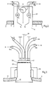
- a valve and nozzle head 17 forming the filling opening 4 according to FIG. 1 is inserted into the outer tube 2.
- a first foam component A is introduced via line 10a, valve 13 and nozzle 14 and a second foam component B via line 10b, valve 15 and nozzle 16 into filling chamber 6.
- the ratio of the two foam components can be determined by the nozzles 14, 16 or also by the valves 13, 15.
- the two components A and B together form the foam 5 according to FIG. 1 in the filling space 6.
- the evacuation takes place via the line 9 and the two-way valve 11.
- evacuation is carried out alternately via the line 9 and the two-way valve 11 and renewed air is supplied via line 12 and the two-way valve 11 to normal pressure in the filling chamber 6.
- Fig. 3 shows a structural design for the airtight arrangement of the valve and nozzle head 17 on the tube 2.
- the entire valve and nozzle head 17 according to FIG. 1 contains a connecting piece 20 with the conical part 35.
- the Connection piece 20 is inserted from the inside into a bore in the outer tube 2 or the sleeve 3 forming the outer tube 2 and braced with the union nut 19 on the outer tube 2.
- the cylindrical conical part 35 thereby jams in the bore of the outer tube 2, attracted by the union nut 19, and thereby causes an airtight seal without additional sealing means.
- O-rings 29 are provided which seal the channels assigned to the lines 9, 10, 12.
- valve levers 18 are provided for manual actuation of the valves 13, 15 and the two-way valve 11 according to FIG. 2.
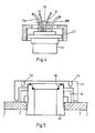
- the connecting piece 20 is clamped by the union nut 19 as in Fig. 3 on the outer tube 2.
- the connecting piece 20 is initially closed by the sealing cap 21 which is screwed onto the upper end of the connecting piece 20 and forms an airtight seal by means of a seal.
- the cap 21 is provided with a tool holder 22.
- the cap 21 is unscrewed from the connecting piece 20 and replaced by the valve and nozzle head 17 according to FIG. 4.
- the lower part of the head 17 engages in the rear rotation 36 and forms an airtight seal with the connecting piece 20 after tightening the union nut 23, which cooperates with the external thread of the connecting piece 20.
- the head 17 is removed again and the connecting piece 20 is pulled completely through the outer tube 2 by tightening the union nut 19.
- the filling opening remaining in the outer tube 2 is sealed gas-tight (e.g. by mirror welding).
- the following advantage is achieved by dividing the entire valve and nozzle head 17 according to FIG. 2 into the actual nozzle head 17 shown in FIG. 4 and the connecting piece 20.
- the nozzle head 17 is a hindrance to assembly due to the hoses forming the lines.
- the filling opening 4 according to FIG. 1 must be closed.
- the connecting piece 20 is inserted immediately and first closed with the cap 21. Thereafter, to complete the sleeve, the cap 21 is removed and replaced by the nozzle head 17 and then tightened with the union nut 23.
- the cap 21 is designed such that it can only be removed with a tool via the tool holder 22 and additionally also covers the union nut 19 in order to protect it against destruction and to keep the nozzle dry by the bell effect.
- connection piece 20 is braced on the outer tube 2 not by a clamping nut, but by a wedge from the lower wedge 27 and the upper wedge 26 between the support ring 24 on the nozzle head 17 and the outer wall of the outer tube 2.
- the lower wedge 27 is located here over the pressure ring 28 on the outer wall of the outer tube 2.
- Fig. 7 the head 17 is braced on the outer tube 2 with the so-called lock gear ring 30 and the clamping nut 31.
- the clamping nut 31, which engages with its internal thread in an external thread of the head 17, is tightened and pulls the head 17 radially outward.
- the toothed ring 30, which engages with its internal thread in an external thread of the head 17, is pressed against the inner wall of the outer tube 2.
- Teeth 38 prevent rotation of the toothed ring 30 on the outer tube 2.
- the toothed ring 30 can either remain in the tube 2, or it is by means of a circular cutter, which in the Tooth ring can be centered, recovered before closing the jacket.
- the individual threads and contact surfaces can be sealed with O-rings.
- valve and nozzle head 17 show a top view and a section A-A of a structural design of the valve and nozzle head 17, which can be clamped to the outer tube 2 by the conical part 35 in the manner described.
- the nozzle cap 32 is shown as protection against contamination and the vacuum connection 33, which is connected to the lines 9, 12 via the individual valves.
- 9 essentially shows the valve levers 18 for the valves for the lines 9, 10, 12.
- FIG. 10 shows another attachment of the head 17 to the outer tube 2 or the sleeve 3 forming the outer tube.
- the head 17 is connected to the clamp 34, which completely surrounds the sleeve 3 in the form of a tension band. Due to the tightening strap 34 tightened by known means, the head 17 is pressed together with corresponding sealing rings onto the surface of the sleeve 3 and thereby forms an airtight seal.
- the 11 shows a device for measuring the optimal filling volume of the filling space 6 with the foam.
- the left end of the cylinder 39 is connected to the evacuated filling chamber 6 via the line 12 and the two-way valve 11.
- the interior 49 is connected to the line 12 in an airtight manner by the bellows 48 and the slide 40.
- the two-way valve is actuated so that line 12 is connected to the evacuated filling chamber 6.
- an air volume penetrates the filling space 6 and restores the atmospheric air pressure therein.
- the slide 40 is moved to the left and thereby likewise moves the measuring rod 41 to the left until the atmospheric pressure in the filling chamber 6 is established.
- the measure of the movement is a measure of the volume of air that has entered the filling space 6 and thus a measure of the volume of foam material that is introduced into the filling space 6 got to.
- Optimal foam density is crucial for good insulation. In order to introduce a really sufficient, but nevertheless not uselessly high amount of foam raw material, such a determination of the air volume of the filling space 6 is advantageous. So far, this amount has been roughly estimated and therefore not optimized. It would also be difficult to estimate in a vacuum, since the filling chamber 6 is not reliably visible.
- Fig. 12 shows an embodiment in the event that a plurality of sleeves 3, e.g. at connection points or repair points. All sleeves 3 are connected in the manner described via sleeve connecting lines and shut-off elements 46 to a common vacuum manifold 44, which is connected to the vacuum pump 42 for the purpose of evacuation.
- the vacuum pump 42 is assigned two analyzer stages 43, which are used to detect the percentage of moisture by electronic moisture detection via sensors and detection of frequency via frequency changes as a result of the changed dielectric in the resonant circuit. This defines what the relationship between removed moisture and destroyed foam pores is. The technical and economic optimum can thus be determined independently of the quality of the existing factory foam, that is the foam in the prefabricated insulated pipes.
- These analyzer stages 43 can be arranged at the discretion of the person skilled in the art in front of or behind the vacuum pump 42.
- Frigen is a suitable gas here, since it also restores the thermal insulation properties in destroyed cells. In deep gaps and cavities that are inaccessible to the new foam, Frigen again improves the thermal insulation properties in the same way as the foam.
- shut-off devices 46 are provided at least at the beginning of each connecting line in order to keep the vacuum losses limited.
- Fig. 13 shows an embodiment for the case that the sleeve 3 is stressed by the vacuum and the external air pressure. Due to the vacuum, the sleeve 3 and the pipe 2 can experience the constriction indicated by dashed lines and thereby make the damaged area less evacuated.
- the outer tube 2 is surrounded in the area of the sleeve 3 by a stable, sleeve-shaped cap 47, in which the valve head 17 is inserted in an airtight manner.
- the cap 47 is sealed airtight with the outer tube 12.
- the supply or removal of air or the introduction of the foaming agent takes place through the sleeve 3, which need not necessarily be sealed airtight with the outer tube 2.
- the stable cap 47 prevents an undesirably high load on the sleeve 3 during the evacuation. After the foaming agent has been introduced, the filling space 6 is filled. Then the cap 47 can be removed, since the air pressure from the outside can then no longer cause any deformation.
- This solution has the additional advantage that the outer tube 2 is no longer in direct contact with the outside air, but the outside temperature is at the cap 47. This can prevent condensation from forming just outside the district heating pipe.
- the outer tube 2 can be cooled by the outside temperature, especially in the cold season, so that water can get caught on the inside of the tube as condensate. This water would be difficult to evacuate.
- the outer tube 2 can be provided with a heat protection cover in the open area, which prevents condensation processes and a heat build-up favoring the evacuation similar to that in FIG Soil caused.
- the covering can consist of a soft blanket, for example of neoprene foam, which is used, for example, as a material for diving suits.
- the evacuation takes place e.g. to a minimum pressure of approx. 1 mbar.
- the lowest possible residual pressure is expedient for the drying process, while, on the other hand, the mechanical stress on the outer pipe or the sleeve is increased by the vacuum as the residual pressure drops. It may therefore be advisable to empirically determine a higher value for the residual pressure, which still results in adequate drying, but does not result in excessive mechanical stress on the outer pipe or sleeve due to the external air pressure and does not destroy the foam.
- FIG. 14 shows an example in which the entire pipeline consists of several commercially available individual parts, each of which is assembled by means of sleeves.
- the damage area extends over the entire delivery length L.
- the length L thus corresponds to the damaged area 8 according to FIG. 1.
- the line pipe is thus treated and reinsulated over the entire length L with the method according to the invention.
- the damage to the filling chamber 6 is indicated by the damage point 52.
- the conduit can also be a roll-shaped tube, in which the inner tube 1 carrying the medium is loose in the Foam is stored.
- 15, 16, 17 show various modifications in the construction of the conduit.
- two inner tubes 1a and 1b are each supported in a support tube 50 within the outer tube 2, the foam 5 again being located between the support tubes 50 and the outer tube 2.
- an inner tube 1 is mounted in a support tube 50.
- a drainage channel 51 is provided at the lower end of the outer tube 2, which serves to drain water that can arise in the space between the outer tube 2 and the inner tube 1.
- the invention is also applicable to lines in which there is no direct foam between the inner tube 1 and outer tube 2, but e.g. an insulating gas, as is often used in roll deliveries.
- an insulating gas e.g. a gas-foam mixture can also be used.
Landscapes
- Engineering & Computer Science (AREA)
- General Engineering & Computer Science (AREA)
- Mechanical Engineering (AREA)
- Thermal Insulation (AREA)
- Laying Of Electric Cables Or Lines Outside (AREA)
Priority Applications (1)
| Application Number | Priority Date | Filing Date | Title |
|---|---|---|---|
| AT86113378T ATE43429T1 (de) | 1985-10-02 | 1986-09-29 | Verfahren und einrichtung zur herstellung eines temperaturisolierten leitungsrohres. |
Applications Claiming Priority (2)
| Application Number | Priority Date | Filing Date | Title |
|---|---|---|---|
| DE3535151 | 1985-10-02 | ||
| DE19853535151 DE3535151A1 (de) | 1985-10-02 | 1985-10-02 | Verfahren und einrichtung zur herstellung eines temperaturisolierten leitungsrohres |
Publications (3)
| Publication Number | Publication Date |
|---|---|
| EP0217343A2 true EP0217343A2 (fr) | 1987-04-08 |
| EP0217343A3 EP0217343A3 (en) | 1987-07-29 |
| EP0217343B1 EP0217343B1 (fr) | 1989-05-24 |
Family
ID=6282563
Family Applications (1)
| Application Number | Title | Priority Date | Filing Date |
|---|---|---|---|
| EP86113378A Expired EP0217343B1 (fr) | 1985-10-02 | 1986-09-29 | Procédé et installation pour la réalisation d'une conduite isolée thermiquement |
Country Status (3)
| Country | Link |
|---|---|
| EP (1) | EP0217343B1 (fr) |
| AT (1) | ATE43429T1 (fr) |
| DE (2) | DE3535151A1 (fr) |
Cited By (3)
| Publication number | Priority date | Publication date | Assignee | Title |
|---|---|---|---|---|
| GB2326210A (en) * | 1997-06-13 | 1998-12-16 | Ramesh Rajagopal | Tube assembly for process fluids using vacuum as thermal insulation |
| NL1026881C2 (nl) * | 2004-08-19 | 2006-02-21 | Nuon Tecno B V | Werkwijze voor het aanleggen van een warmtedistributiesysteem. |
| CN106113492A (zh) * | 2016-08-25 | 2016-11-16 | 尤文聘 | 一种胸围背扣的公扣机送料装置 |
Families Citing this family (1)
| Publication number | Priority date | Publication date | Assignee | Title |
|---|---|---|---|---|
| AT392149B (de) * | 1989-06-06 | 1991-01-25 | Egger K Kunststoffwerk | Verfahren zum verbinden isolierter leitungsrohre |
Family Cites Families (6)
| Publication number | Priority date | Publication date | Assignee | Title |
|---|---|---|---|---|
| BE790619A (fr) * | 1971-10-28 | 1973-02-15 | Rasmussen As E | Procede de constitution de joints isoles en gaine de tube pour sa mise en oeuvre |
| FR2223169A2 (en) * | 1973-04-02 | 1974-10-25 | Peugeot & Renault | Foam moulding - using cooled mixture with increased catalyst |
| FR2428519A1 (fr) * | 1978-06-13 | 1980-01-11 | Ameublement Ind Et Tech | Bouchon pour trou de coulee de matiere expansee dans un moule |
| DE2841934A1 (de) * | 1978-09-27 | 1980-04-17 | Kabel Metallwerke Ghh | Waermeisoliertes leitungsrohr und verfahren zu seiner herstellung |
| DE3110503A1 (de) * | 1981-03-18 | 1982-10-07 | Kabel- und Metallwerke Gutehoffnungshütte AG, 3000 Hannover | "verfahren zur herstellung einer verbindungsstelle fuer waermeisolierte leitungsrohre |
| SE8300252L (sv) * | 1983-01-19 | 1984-07-20 | Dansk Rorind | Sett att skarva tva forisolerade ror och en skarvhylsa att anvendas vid tillempning av nemnda sett |
-
1985
- 1985-10-02 DE DE19853535151 patent/DE3535151A1/de not_active Withdrawn
-
1986
- 1986-09-29 EP EP86113378A patent/EP0217343B1/fr not_active Expired
- 1986-09-29 DE DE8686113378T patent/DE3663583D1/de not_active Expired
- 1986-09-29 AT AT86113378T patent/ATE43429T1/de not_active IP Right Cessation
Cited By (5)
| Publication number | Priority date | Publication date | Assignee | Title |
|---|---|---|---|---|
| GB2326210A (en) * | 1997-06-13 | 1998-12-16 | Ramesh Rajagopal | Tube assembly for process fluids using vacuum as thermal insulation |
| NL1026881C2 (nl) * | 2004-08-19 | 2006-02-21 | Nuon Tecno B V | Werkwijze voor het aanleggen van een warmtedistributiesysteem. |
| EP1628069A1 (fr) * | 2004-08-19 | 2006-02-22 | Nuon Tecno B.V. | Méthode d'installation d'un système de distribution de chaleur |
| CN106113492A (zh) * | 2016-08-25 | 2016-11-16 | 尤文聘 | 一种胸围背扣的公扣机送料装置 |
| CN106113492B (zh) * | 2016-08-25 | 2023-05-09 | 尤文聘 | 一种胸围背扣的公扣机送料装置 |
Also Published As
| Publication number | Publication date |
|---|---|
| DE3663583D1 (en) | 1989-06-29 |
| ATE43429T1 (de) | 1989-06-15 |
| DE3535151A1 (de) | 1987-04-09 |
| EP0217343B1 (fr) | 1989-05-24 |
| EP0217343A3 (en) | 1987-07-29 |
Similar Documents
| Publication | Publication Date | Title |
|---|---|---|
| DE3318524C2 (fr) | ||
| DE2252295A1 (de) | Verfahren und vorrichtung zur verbindung isolierter rohrlaengen | |
| DE2053725A1 (de) | Verfahren und Vorrichtung zum Abdich ten einer Leckstelle in Leitungen | |
| EP0217343B1 (fr) | Procédé et installation pour la réalisation d'une conduite isolée thermiquement | |
| EP1101990A1 (fr) | Procédé et dispositif pour étanchéifier les fentes | |
| DE8525261U1 (de) | Verlängerbarer Verbinder für hydraulische Anlagen | |
| EP0603775A1 (fr) | Méthode pour effectuer des connexions étanches entre un tuyau et un raccord de tuyau, et un raccord de tuyau serrable utilisé à cet effet | |
| EP1795796B1 (fr) | Tuyau de canalisation pour le transport de fluides cryogéniques | |
| DE60310940T2 (de) | Verfahren zum abdichten und/oder wiederinstandsetzen von rohren | |
| DE19513559C2 (de) | Vorrichtung zum Herstellen von verformten mehrwandigen Rohren mit einem oder mehreren Hohlräumen zwischen den Wandungen | |
| DE29521615U1 (de) | Rohrleitung für Abwasserleitungssysteme | |
| DE2743380A1 (de) | Kuehlplatte fuer metallurgische, mit einer feuerfesten auskleidung versehene oefen | |
| EP0360113B1 (fr) | Procédé pour la décharge non polluante d'un système frigorifique | |
| DE3135382A1 (de) | Reparaturstopfen fuer waermetauscherrohre, insbesondere fuer dampferzeuger von druckwasser-kernkraftwerken | |
| DE7314756U (de) | Armatur fur Rohrleitungen | |
| EP0040791B1 (fr) | Introduction dans la maison de tuyauteries de fluide, notamment pour conduits de gaz et d'eau | |
| DE3815083C2 (fr) | ||
| DE4116267A1 (de) | Verfahren und mittel zum abdichten einer fuge in einem baukoerper | |
| DE19804651A1 (de) | Verfahren zur Herstellung einer kraftschlüssigen Verbindung eines Futterrohres mit dem Mantelrohr einer Rohrwaffe | |
| EP0611912A1 (fr) | Méthode de réalisation d'une connextion entre un tuyau principal et un tuyau de branchement et appareil pour sa mise en oeuvre | |
| DE19717209A1 (de) | Rohrschelle | |
| DE2733161A1 (de) | Dichtungskoerper und verfahren zu seiner herstellung | |
| DE3801472A1 (de) | Verfahren zum sanieren einer im erdreich verlegten rohrleitung | |
| DE9017703U1 (de) | Vorrichtung zur Kühlung der Laufbuchsen von Schiffswellenlagern | |
| DE1914124C3 (de) | Glas- oder Quarzglas-Rohr mit Metall-Mantel |
Legal Events
| Date | Code | Title | Description |
|---|---|---|---|
| PUAI | Public reference made under article 153(3) epc to a published international application that has entered the european phase |
Free format text: ORIGINAL CODE: 0009012 |
|
| AK | Designated contracting states |
Kind code of ref document: A2 Designated state(s): AT BE CH DE FR GB IT LI LU NL SE |
|
| PUAL | Search report despatched |
Free format text: ORIGINAL CODE: 0009013 |
|
| AK | Designated contracting states |
Kind code of ref document: A3 Designated state(s): AT BE CH DE FR GB IT LI LU NL SE |
|
| 17P | Request for examination filed |
Effective date: 19880119 |
|
| 17Q | First examination report despatched |
Effective date: 19880811 |
|
| GRAA | (expected) grant |
Free format text: ORIGINAL CODE: 0009210 |
|
| AK | Designated contracting states |
Kind code of ref document: B1 Designated state(s): AT BE CH DE FR GB IT LI LU NL SE |
|
| REF | Corresponds to: |
Ref document number: 43429 Country of ref document: AT Date of ref document: 19890615 Kind code of ref document: T |
|
| ITF | It: translation for a ep patent filed | ||
| REF | Corresponds to: |
Ref document number: 3663583 Country of ref document: DE Date of ref document: 19890629 |
|
| ET | Fr: translation filed | ||
| GBT | Gb: translation of ep patent filed (gb section 77(6)(a)/1977) | ||
| PG25 | Lapsed in a contracting state [announced via postgrant information from national office to epo] |
Ref country code: LU Free format text: LAPSE BECAUSE OF NON-PAYMENT OF DUE FEES Effective date: 19890930 |
|
| PLBE | No opposition filed within time limit |
Free format text: ORIGINAL CODE: 0009261 |
|
| STAA | Information on the status of an ep patent application or granted ep patent |
Free format text: STATUS: NO OPPOSITION FILED WITHIN TIME LIMIT |
|
| 26N | No opposition filed | ||
| ITTA | It: last paid annual fee | ||
| PGFP | Annual fee paid to national office [announced via postgrant information from national office to epo] |
Ref country code: SE Payment date: 19940822 Year of fee payment: 9 |
|
| PGFP | Annual fee paid to national office [announced via postgrant information from national office to epo] |
Ref country code: AT Payment date: 19940912 Year of fee payment: 9 |
|
| PGFP | Annual fee paid to national office [announced via postgrant information from national office to epo] |
Ref country code: BE Payment date: 19940914 Year of fee payment: 9 |
|
| PGFP | Annual fee paid to national office [announced via postgrant information from national office to epo] |
Ref country code: GB Payment date: 19940919 Year of fee payment: 9 |
|
| PGFP | Annual fee paid to national office [announced via postgrant information from national office to epo] |
Ref country code: FR Payment date: 19940921 Year of fee payment: 9 |
|
| PGFP | Annual fee paid to national office [announced via postgrant information from national office to epo] |
Ref country code: NL Payment date: 19940930 Year of fee payment: 9 |
|
| EAL | Se: european patent in force in sweden |
Ref document number: 86113378.3 |
|
| PGFP | Annual fee paid to national office [announced via postgrant information from national office to epo] |
Ref country code: DE Payment date: 19950822 Year of fee payment: 10 |
|
| PG25 | Lapsed in a contracting state [announced via postgrant information from national office to epo] |
Ref country code: GB Effective date: 19950929 Ref country code: AT Effective date: 19950929 |
|
| PG25 | Lapsed in a contracting state [announced via postgrant information from national office to epo] |
Ref country code: SE Effective date: 19950930 Ref country code: BE Effective date: 19950930 |
|
| PGFP | Annual fee paid to national office [announced via postgrant information from national office to epo] |
Ref country code: CH Payment date: 19951201 Year of fee payment: 10 |
|
| BERE | Be: lapsed |
Owner name: BRANDES BERND Effective date: 19950930 |
|
| PG25 | Lapsed in a contracting state [announced via postgrant information from national office to epo] |
Ref country code: NL Effective date: 19960401 |
|
| GBPC | Gb: european patent ceased through non-payment of renewal fee |
Effective date: 19950929 |
|
| PG25 | Lapsed in a contracting state [announced via postgrant information from national office to epo] |
Ref country code: FR Effective date: 19960531 |
|
| NLV4 | Nl: lapsed or anulled due to non-payment of the annual fee |
Effective date: 19960401 |
|
| EUG | Se: european patent has lapsed |
Ref document number: 86113378.3 |
|
| REG | Reference to a national code |
Ref country code: FR Ref legal event code: ST |
|
| PG25 | Lapsed in a contracting state [announced via postgrant information from national office to epo] |
Ref country code: LI Effective date: 19960930 Ref country code: CH Effective date: 19960930 |
|
| REG | Reference to a national code |
Ref country code: CH Ref legal event code: PL |
|
| PG25 | Lapsed in a contracting state [announced via postgrant information from national office to epo] |
Ref country code: DE Effective date: 19970603 |
|
| PG25 | Lapsed in a contracting state [announced via postgrant information from national office to epo] |
Ref country code: IT Free format text: LAPSE BECAUSE OF NON-PAYMENT OF DUE FEES;WARNING: LAPSES OF ITALIAN PATENTS WITH EFFECTIVE DATE BEFORE 2007 MAY HAVE OCCURRED AT ANY TIME BEFORE 2007. THE CORRECT EFFECTIVE DATE MAY BE DIFFERENT FROM THE ONE RECORDED. Effective date: 20050929 |