EP0217343A2 - Verfahren und Einrichtung zur Herstellung eines temperaturisolierten Leitungsrohres - Google Patents
Verfahren und Einrichtung zur Herstellung eines temperaturisolierten Leitungsrohres Download PDFInfo
- Publication number
- EP0217343A2 EP0217343A2 EP86113378A EP86113378A EP0217343A2 EP 0217343 A2 EP0217343 A2 EP 0217343A2 EP 86113378 A EP86113378 A EP 86113378A EP 86113378 A EP86113378 A EP 86113378A EP 0217343 A2 EP0217343 A2 EP 0217343A2
- Authority
- EP
- European Patent Office
- Prior art keywords
- outer tube
- foam
- annular space
- sleeve
- foaming agent
- Prior art date
- Legal status (The legal status is an assumption and is not a legal conclusion. Google has not performed a legal analysis and makes no representation as to the accuracy of the status listed.)
- Granted
Links
Images



Classifications
-
- B—PERFORMING OPERATIONS; TRANSPORTING
- B29—WORKING OF PLASTICS; WORKING OF SUBSTANCES IN A PLASTIC STATE IN GENERAL
- B29C—SHAPING OR JOINING OF PLASTICS; SHAPING OF MATERIAL IN A PLASTIC STATE, NOT OTHERWISE PROVIDED FOR; AFTER-TREATMENT OF THE SHAPED PRODUCTS, e.g. REPAIRING
- B29C44/00—Shaping by internal pressure generated in the material, e.g. swelling or foaming ; Producing porous or cellular expanded plastics articles
- B29C44/02—Shaping by internal pressure generated in the material, e.g. swelling or foaming ; Producing porous or cellular expanded plastics articles for articles of definite length, i.e. discrete articles
- B29C44/12—Incorporating or moulding on preformed parts, e.g. inserts or reinforcements
- B29C44/1295—Foaming around pipe joints
-
- B—PERFORMING OPERATIONS; TRANSPORTING
- B29—WORKING OF PLASTICS; WORKING OF SUBSTANCES IN A PLASTIC STATE IN GENERAL
- B29C—SHAPING OR JOINING OF PLASTICS; SHAPING OF MATERIAL IN A PLASTIC STATE, NOT OTHERWISE PROVIDED FOR; AFTER-TREATMENT OF THE SHAPED PRODUCTS, e.g. REPAIRING
- B29C44/00—Shaping by internal pressure generated in the material, e.g. swelling or foaming ; Producing porous or cellular expanded plastics articles
- B29C44/02—Shaping by internal pressure generated in the material, e.g. swelling or foaming ; Producing porous or cellular expanded plastics articles for articles of definite length, i.e. discrete articles
- B29C44/12—Incorporating or moulding on preformed parts, e.g. inserts or reinforcements
- B29C44/1228—Joining preformed parts by the expanding material
- B29C44/1242—Joining preformed parts by the expanding material the preformed parts being concentric
-
- F—MECHANICAL ENGINEERING; LIGHTING; HEATING; WEAPONS; BLASTING
- F16—ENGINEERING ELEMENTS AND UNITS; GENERAL MEASURES FOR PRODUCING AND MAINTAINING EFFECTIVE FUNCTIONING OF MACHINES OR INSTALLATIONS; THERMAL INSULATION IN GENERAL
- F16L—PIPES; JOINTS OR FITTINGS FOR PIPES; SUPPORTS FOR PIPES, CABLES OR PROTECTIVE TUBING; MEANS FOR THERMAL INSULATION IN GENERAL
- F16L59/00—Thermal insulation in general
- F16L59/14—Arrangements for the insulation of pipes or pipe systems
- F16L59/16—Arrangements specially adapted to local requirements at flanges, junctions, valves or the like
- F16L59/18—Arrangements specially adapted to local requirements at flanges, junctions, valves or the like adapted for joints
- F16L59/20—Arrangements specially adapted to local requirements at flanges, junctions, valves or the like adapted for joints for non-disconnectable joints
Definitions
- the invention relates to a method and a device for producing a temperature-insulated conduit according to the preamble of claim 1.
- line pipes which consist of an inner pipe guiding the medium, an outer pipe surrounding the inner pipe at a distance and a foam used for thermal insulation in the annular space between the inner pipe and the outer pipe.
- the inner tube is preferably made of steel, the outer tube also made of steel or plastic, preferably polyethylene. Polyurethane is preferably used as the foam for the thermal insulation. It can also be refrigeration pipes. District cooling pipes are often installed in southern countries (example Saudi Arabia), which often must not be switched off. According to the old form, condensate was included in the pipe in almost every repair sleeve. The consequences of this fact are not yet foreseeable.
- the pipeline can also be an actively heated line for pure media transport, for example a sulfur pipeline or an oil pipeline such as the "Alaska pipeline” for temperature-controlled raw material transport.
- conduit pipes are manufactured in certain lengths of several meters and then assembled on site to form a longer pipe, for example a so-called pipeline or district heating pipe.
- the inner tube protrudes from the end of such a conduit End faces of the outer tube and the foam so that the ends of the inner tubes can be welded together by two conduits.
- a certain area of the inner tube of approximately 0.5 m is thus initially exposed, and is therefore not surrounded by the foam and also not by the outer tube.
- the outer tube and the foam must also be temporarily removed at the repair site so that there is access to the defective inner tube.
- connection point or repair point also referred to as post-insulation
- post-insulation to scrape out all the damp spots from the foam between the inner pipe and the outer pipe, so that after the closure and the foaming of the conduit there is as little residual moisture as possible.
- this solution is wage-intensive and also subject to highly subjective impressions.
- the invention has for its object to provide a method and a device with which in the manufacture of the sleeves, especially at joints and repair points, a perfect foaming of the annular space can be achieved without great manual effort and with the greatest possible avoidance of residual moisture.
- any moisture is first removed from the annular space at a joint or repair site by the production of the vacuum. This is due to the fact that as the air pressure drops, the residual moisture evaporates automatically and is removed by the evacuation process. This also applies in an advantageous manner to residual moisture which is located at the ends of the existing foam, the so-called factory foam. It is therefore no longer necessary to manually scrape out all moist areas from this so-called factory foam.
- the annular space which is then foamed again with the foaming agent to form the foam, is then largely freed of moisture already when foaming. It has previously been assumed that the foam is destroyed by vacuum and the jacket pipes should break in. Both points are not as relevant as feared and can be managed through targeted handling of the vacuum. in the In connection with the foaming of the connection point, inaccessible gaps etc. have to be filled with insulating gas, which can further improve the insulating properties.
- the solution according to the invention permits simple, cost-saving installation or repair, without sacrificing safety.
- the damaged areas no longer have to be opened over longer distances in order to remove damp foam or suspected moisture, since this task is carried out by the vacuum itself.
- the vacuum is able to cause residual moisture to outgas through cracks and joints.
- the resulting savings in civil engineering and material expenses can be of the order of 50% of previous expenses.
- the method according to the invention can be used to produce pipe closures after connection or repair with less work and greater security with regard to durability. For such cases, the method according to the invention enables savings of approximately 90% of the previously usual expenditure in relation to the total costs of a new installation.
- the evacuation of the annular space is preferably carried out in a so-called pulsating operation, in that the vacuum is produced several times in succession by means of a pumping process over a longer period of time and is then broken down again by the supply of air becomes. This can improve the removal of residual moisture.
- air is preferably preheated again and supplied with low air humidity, which is able to absorb additional moisture.
- the amount of gas to remove the vacuum can be measured after the evacuation and can be used to determine the optimal volume for the foaming agent.
- the gas volume is e.g. from a container, which is enclosed by a body that can be defined by measurement technology. From the reduction in the volume of the gas container, it is then possible to draw direct conclusions about the volume in the annular space in the area of the sleeve and thus about the need for foaming agents.
- the same measurement can be chosen by the person skilled in the art, e.g. can also be made using a gas meter. This ensures that a really sufficient, but nonetheless not unnecessarily large amount of foaming agent or foam raw material is introduced into the annular space.
- several sleeves are preferably connected to the vacuum pump at the same time via a vacuum distribution and switched on or off individually or in sections via shut-off valves.
- the increase in air pressure in the annulus as a function of time can be used as a measure of the quality of the moisture removal. As a rule, this air pressure rises slowly depending on the time due to burst bubbles in the foam, while this increase takes place much more quickly due to residual moisture. The slow increase due to burst bubbles is less disadvantageous than the faster pressure increase due to residual moisture.
- a plurality of connections for different foaming agent components are provided at the second end of a nozzle head, each with a valve connected to the first end.
- two connections for gas extraction for evacuation and for gas supply for volume measurement are provided and can optionally be connected to the first end via a two-way valve.
- a union nut engages in an external thread of the valve and nozzle head, which nut is supported on the outer wall of the outer tube.
- a conical part of the nozzle head is formed by one end of a connecting piece, on the other end of which the valve and nozzle head or a sealing cap can optionally be screwed on in an airtight manner.
- the nozzle head can be braced on the outer tube with a wedge between a support ring of the nozzle head and the outer wall of the outer tube.
- the wedge consists of an upper wedge and a lower wedge, which have opposite inclinations and together form a cuboid part with a variable thickness that is constant over the length.
- the nozzle head preferably engages at the first end with a thread in a counter toothing ring which lies in a bore in the outer tube and engages behind the edge of the bore on the inner wall of the outer tube with an edge which is angled outward.
- a union nut engages in an external thread of the nozzle head, which is supported on the outer wall of the outer tube.
- the toothed ring mentioned is provided with teeth on its edge abutting the inner wall of the outer tube.
- the inner tube and the outer tube are connected in an airtight manner to the conduit at the end facing away from the evacuated filling chamber with a sleeve, sleeve or the like.
- the outer tube or the sleeve is preferably surrounded by a heat-insulating sheath in order to avoid condensation in the annular space.
- the process can also be used for foam-insulated pipes that are supplied commercially in roll form, with the application then extending over the entire delivery length.
- the following advantages are additionally achieved by the solution according to the invention: A reliable control of success and thereby high profitability.
- the successful repair can be the same or better than the existing original sleeve.
- Reliable drying of the sleeve is achieved, which was previously not possible even with new systems. Up until now, it was possible to scrape out the end faces of the foam, although problem areas were mostly not reached.
- the drying introduced according to the invention can also be effective for such difficult to access areas. With new systems, there is often the need to foam many sleeves in one go. The day / night cycle allowed condensate to get into the non-foamed interior prepared for foaming. The damage that this caused to the sleeves directly or to the integrated moisture sensors is reduced by the solution according to the invention.
- Fiber-insulated or half-shell insulated, roll-shaped pipe systems are known, the ends of which are also provided with caps to protect against moisture.
- very careful and careful drying of the individual sleeve areas is possible.
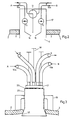
- Fig. 1 shows a conduit with the inner tube 1, the outer tube 2 and the foam 5 in the annular space formed by the tubes 1,2.
- the inner tubes 1 of two initially separate line tubes are connected to one another by a weld 7. So that this connection can be established, the inner tubes 1 protrude beyond the ends of the outer tubes 2 and the foam 5.
- the area A must therefore be completed again by the foam 5 and the outer tube 2 after the connection of the inner tubes or repair.
- the hatched area 8 shows the area of the foam 5 which is affected by moisture and which would have to be removed in the known method.
- the outer tube 2 is surrounded by the sleeve 3, which has a filling opening 4.
- Sleeve 3 and outer tube 2 form an airtight seal.
- the evacuation process via line 9 thus first evacuates the filling chamber 6 and frees it of any residual moisture.
- the foaming agent is introduced via the line 10 via the filling opening 4, in such an amount that the filling space 6 is properly filled with foam. A largely continuous transition of the foam 5 is then achieved in the region 8 without any noteworthy irregularities.
- the amount of foam material to be introduced via line 10 is preferably determined by the gas volume which is required after evacuating the filling chamber 6 in order to restore the normal air pressure in the filling chamber 6 from the evacuated state. After the two processes, namely the evacuation and the filling of the filling space 6, the filling opening 4 is closed gas-tight.
- a valve and nozzle head 17 forming the filling opening 4 according to FIG. 1 is inserted into the outer tube 2.
- a first foam component A is introduced via line 10a, valve 13 and nozzle 14 and a second foam component B via line 10b, valve 15 and nozzle 16 into filling chamber 6.
- the ratio of the two foam components can be determined by the nozzles 14, 16 or also by the valves 13, 15.
- the two components A and B together form the foam 5 according to FIG. 1 in the filling space 6.
- the evacuation takes place via the line 9 and the two-way valve 11.
- evacuation is carried out alternately via the line 9 and the two-way valve 11 and renewed air is supplied via line 12 and the two-way valve 11 to normal pressure in the filling chamber 6.
- Fig. 3 shows a structural design for the airtight arrangement of the valve and nozzle head 17 on the tube 2.
- the entire valve and nozzle head 17 according to FIG. 1 contains a connecting piece 20 with the conical part 35.
- the Connection piece 20 is inserted from the inside into a bore in the outer tube 2 or the sleeve 3 forming the outer tube 2 and braced with the union nut 19 on the outer tube 2.
- the cylindrical conical part 35 thereby jams in the bore of the outer tube 2, attracted by the union nut 19, and thereby causes an airtight seal without additional sealing means.
- O-rings 29 are provided which seal the channels assigned to the lines 9, 10, 12.
- valve levers 18 are provided for manual actuation of the valves 13, 15 and the two-way valve 11 according to FIG. 2.
- the connecting piece 20 is clamped by the union nut 19 as in Fig. 3 on the outer tube 2.
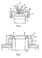
- the connecting piece 20 is initially closed by the sealing cap 21 which is screwed onto the upper end of the connecting piece 20 and forms an airtight seal by means of a seal.
- the cap 21 is provided with a tool holder 22.
- the cap 21 is unscrewed from the connecting piece 20 and replaced by the valve and nozzle head 17 according to FIG. 4.
- the lower part of the head 17 engages in the rear rotation 36 and forms an airtight seal with the connecting piece 20 after tightening the union nut 23, which cooperates with the external thread of the connecting piece 20.
- the head 17 is removed again and the connecting piece 20 is pulled completely through the outer tube 2 by tightening the union nut 19.
- the filling opening remaining in the outer tube 2 is sealed gas-tight (e.g. by mirror welding).
- the following advantage is achieved by dividing the entire valve and nozzle head 17 according to FIG. 2 into the actual nozzle head 17 shown in FIG. 4 and the connecting piece 20.
- the nozzle head 17 is a hindrance to assembly due to the hoses forming the lines.
- the filling opening 4 according to FIG. 1 must be closed.
- the connecting piece 20 is inserted immediately and first closed with the cap 21. Thereafter, to complete the sleeve, the cap 21 is removed and replaced by the nozzle head 17 and then tightened with the union nut 23.
- the cap 21 is designed such that it can only be removed with a tool via the tool holder 22 and additionally also covers the union nut 19 in order to protect it against destruction and to keep the nozzle dry by the bell effect.
- connection piece 20 is braced on the outer tube 2 not by a clamping nut, but by a wedge from the lower wedge 27 and the upper wedge 26 between the support ring 24 on the nozzle head 17 and the outer wall of the outer tube 2.
- the lower wedge 27 is located here over the pressure ring 28 on the outer wall of the outer tube 2.
- Fig. 7 the head 17 is braced on the outer tube 2 with the so-called lock gear ring 30 and the clamping nut 31.
- the clamping nut 31, which engages with its internal thread in an external thread of the head 17, is tightened and pulls the head 17 radially outward.
- the toothed ring 30, which engages with its internal thread in an external thread of the head 17, is pressed against the inner wall of the outer tube 2.
- Teeth 38 prevent rotation of the toothed ring 30 on the outer tube 2.
- the toothed ring 30 can either remain in the tube 2, or it is by means of a circular cutter, which in the Tooth ring can be centered, recovered before closing the jacket.
- the individual threads and contact surfaces can be sealed with O-rings.
- valve and nozzle head 17 show a top view and a section A-A of a structural design of the valve and nozzle head 17, which can be clamped to the outer tube 2 by the conical part 35 in the manner described.
- the nozzle cap 32 is shown as protection against contamination and the vacuum connection 33, which is connected to the lines 9, 12 via the individual valves.
- 9 essentially shows the valve levers 18 for the valves for the lines 9, 10, 12.
- FIG. 10 shows another attachment of the head 17 to the outer tube 2 or the sleeve 3 forming the outer tube.
- the head 17 is connected to the clamp 34, which completely surrounds the sleeve 3 in the form of a tension band. Due to the tightening strap 34 tightened by known means, the head 17 is pressed together with corresponding sealing rings onto the surface of the sleeve 3 and thereby forms an airtight seal.
- the 11 shows a device for measuring the optimal filling volume of the filling space 6 with the foam.
- the left end of the cylinder 39 is connected to the evacuated filling chamber 6 via the line 12 and the two-way valve 11.
- the interior 49 is connected to the line 12 in an airtight manner by the bellows 48 and the slide 40.
- the two-way valve is actuated so that line 12 is connected to the evacuated filling chamber 6.
- an air volume penetrates the filling space 6 and restores the atmospheric air pressure therein.
- the slide 40 is moved to the left and thereby likewise moves the measuring rod 41 to the left until the atmospheric pressure in the filling chamber 6 is established.
- the measure of the movement is a measure of the volume of air that has entered the filling space 6 and thus a measure of the volume of foam material that is introduced into the filling space 6 got to.
- Optimal foam density is crucial for good insulation. In order to introduce a really sufficient, but nevertheless not uselessly high amount of foam raw material, such a determination of the air volume of the filling space 6 is advantageous. So far, this amount has been roughly estimated and therefore not optimized. It would also be difficult to estimate in a vacuum, since the filling chamber 6 is not reliably visible.
- Fig. 12 shows an embodiment in the event that a plurality of sleeves 3, e.g. at connection points or repair points. All sleeves 3 are connected in the manner described via sleeve connecting lines and shut-off elements 46 to a common vacuum manifold 44, which is connected to the vacuum pump 42 for the purpose of evacuation.
- the vacuum pump 42 is assigned two analyzer stages 43, which are used to detect the percentage of moisture by electronic moisture detection via sensors and detection of frequency via frequency changes as a result of the changed dielectric in the resonant circuit. This defines what the relationship between removed moisture and destroyed foam pores is. The technical and economic optimum can thus be determined independently of the quality of the existing factory foam, that is the foam in the prefabricated insulated pipes.
- These analyzer stages 43 can be arranged at the discretion of the person skilled in the art in front of or behind the vacuum pump 42.
- Frigen is a suitable gas here, since it also restores the thermal insulation properties in destroyed cells. In deep gaps and cavities that are inaccessible to the new foam, Frigen again improves the thermal insulation properties in the same way as the foam.
- shut-off devices 46 are provided at least at the beginning of each connecting line in order to keep the vacuum losses limited.
- Fig. 13 shows an embodiment for the case that the sleeve 3 is stressed by the vacuum and the external air pressure. Due to the vacuum, the sleeve 3 and the pipe 2 can experience the constriction indicated by dashed lines and thereby make the damaged area less evacuated.
- the outer tube 2 is surrounded in the area of the sleeve 3 by a stable, sleeve-shaped cap 47, in which the valve head 17 is inserted in an airtight manner.
- the cap 47 is sealed airtight with the outer tube 12.
- the supply or removal of air or the introduction of the foaming agent takes place through the sleeve 3, which need not necessarily be sealed airtight with the outer tube 2.
- the stable cap 47 prevents an undesirably high load on the sleeve 3 during the evacuation. After the foaming agent has been introduced, the filling space 6 is filled. Then the cap 47 can be removed, since the air pressure from the outside can then no longer cause any deformation.
- This solution has the additional advantage that the outer tube 2 is no longer in direct contact with the outside air, but the outside temperature is at the cap 47. This can prevent condensation from forming just outside the district heating pipe.
- the outer tube 2 can be cooled by the outside temperature, especially in the cold season, so that water can get caught on the inside of the tube as condensate. This water would be difficult to evacuate.
- the outer tube 2 can be provided with a heat protection cover in the open area, which prevents condensation processes and a heat build-up favoring the evacuation similar to that in FIG Soil caused.
- the covering can consist of a soft blanket, for example of neoprene foam, which is used, for example, as a material for diving suits.
- the evacuation takes place e.g. to a minimum pressure of approx. 1 mbar.
- the lowest possible residual pressure is expedient for the drying process, while, on the other hand, the mechanical stress on the outer pipe or the sleeve is increased by the vacuum as the residual pressure drops. It may therefore be advisable to empirically determine a higher value for the residual pressure, which still results in adequate drying, but does not result in excessive mechanical stress on the outer pipe or sleeve due to the external air pressure and does not destroy the foam.
- FIG. 14 shows an example in which the entire pipeline consists of several commercially available individual parts, each of which is assembled by means of sleeves.
- the damage area extends over the entire delivery length L.
- the length L thus corresponds to the damaged area 8 according to FIG. 1.
- the line pipe is thus treated and reinsulated over the entire length L with the method according to the invention.
- the damage to the filling chamber 6 is indicated by the damage point 52.
- the conduit can also be a roll-shaped tube, in which the inner tube 1 carrying the medium is loose in the Foam is stored.
- 15, 16, 17 show various modifications in the construction of the conduit.
- two inner tubes 1a and 1b are each supported in a support tube 50 within the outer tube 2, the foam 5 again being located between the support tubes 50 and the outer tube 2.
- an inner tube 1 is mounted in a support tube 50.
- a drainage channel 51 is provided at the lower end of the outer tube 2, which serves to drain water that can arise in the space between the outer tube 2 and the inner tube 1.
- the invention is also applicable to lines in which there is no direct foam between the inner tube 1 and outer tube 2, but e.g. an insulating gas, as is often used in roll deliveries.
- an insulating gas e.g. a gas-foam mixture can also be used.
Landscapes
- Engineering & Computer Science (AREA)
- General Engineering & Computer Science (AREA)
- Mechanical Engineering (AREA)
- Thermal Insulation (AREA)
- Laying Of Electric Cables Or Lines Outside (AREA)
Abstract
Description
- Die Erfindung betrifft ein Verfahren und eine Einrichtung zur Herstellung eines temperaturisolierten Leitungsrohres gemäß dem Oberbegriff des Anspruchs 1.
- Für die wärmeisolierte Übertragung flüssiger und gasförmiger Medien, z.B. für eine Fernheizung, sind Leitungsrohre bekannt, die aus einem das Medium führenden Innenrohr, einem das Innenrohr im Abstand umgebenden Außenrohr und einem zur Wärmeisolierung dienenden Schaumstoff in dem Ringraum zwischen Innenrohr und Außenrohr bestehen. Das Innenrohr ist dabei vorzugsweise aus Stahl, das Außenrohr ebenfalls aus Stahl oder Kunststoff, vorzugsweise Polyäthylen, hergestellt. Als Schaumstoff für die Wärmeisolierung wird vorzugsweise Polyurethan verwendet. Es kann sich auch um Kälteleitungen handeln. In südlichen Ländern (Beispiel Saudi-Arabien) sind häufig Fernkälteleitungen installiert, die oft nicht abgeschaltet werden dürfen. Nach alter Form wurde in fast jeder Reparaturmuffe Kondensat am Rohr mit eingeschlossen. Die Folgen aus dieser Tatsache sind bisher nicht absehbar. Es kann sich bei der Rohrleitung auch um eine aktiv beheizte Leitung für reinen Medientransport handeln, beispielsweise eine Schwefelpipeline oder eine Ölpipeline wie die "Alaska-Pipeline" zum temperierten Rohstoff-Transport.
- Bei derartigen Leitungen ist es auch bekannt, in den im Ringraum vorgesehenen Schaumstoff einen sogenannten Meldeleiter einzubetten, der als Feuchtigkeitsfühler ausgebildet ist und mit dem eine Leckage des Innenrohres geortet werden kann.
- Derartige Leitungsrohre werden in bestimmten Längen von mehreren Metern hergestellt und dann vor Ort zu einer längeren Leitung, beispielsweise einer sogenannten Pipeline oder Fernheizleitung, zusammengesetzt. Zu diesem Zweck ragt jeweils am Ende eines derartigen Leitungsrohres das Innenrohr über die Stirnenden des Außenrohres und des Schaumstoffes hinaus, damit jeweils die Enden der Innenrohre von zwei Leitungsrohren miteinander verschweißt werden können. Dabei liegt also zunächst ein gewisser Bereich des Innenrohres von ca. 0,5 m frei, ist also nicht von dem Schaumstoff und auch nicht von dem Außenrohr umgeben.
- Bei einer Reparatur, z.B. aufgrund einer Leckage, müssen ebenfalls an der Reparaturstelle das Außenrohr und der Schaumstoff vorübergehend entfernt werden, damit ein Zugriff zu dem defekten Innenrohr besteht.
- In den genannten Fällen besteht somit die Aufgabe, nach dem Zusammenschweißen der Innenrohre von zwei Rohrleitungen oder nach einer erfolgten Reparatur den Ringraum wieder mit Schaumstoff aufzufüllen und das unterbrochene Außenrohr mit einer Muffe wieder hermetisch zu verschließen. Dabei ist es besonders wichtig, daß in dem Ringraum keine Restfeuchtigkeit verbleibt. Eine verbleibende Restfeuchtigkeit in dem Ringraum kann auf lange Sicht den Schaumstoff zerstören, insbesondere durch einen erhöhten Dampfdruck die Zellwände des Schaumstoffes beschädigen. Feuchtigkeit bewirkt außerdem eine Korrosion an Stahlrohren, kann zusammen mit dem Schaumstoff Salzsäure bilden und außerdem die Wärmeisolierwirkung des Schaumstoffes verschlechtern.
- Es ist daher bekannt, an einer Verbindungsstelle oder Reparaturstelle, auch Nachisolierstelle genannt, aus dem Schaumstoff zwischen Innenrohr und Außenrohr nach optischem Eindruck alle feuchten Stellen auszukratzen, damit nach dem Verschluß und dem Ausschäumen des Leitungsrohres möglichst keine Restfeuchtigkeit verbleibt. Diese Lösung ist jedoch lohnintensiv und außerdem stark subjektiven Eindrücken unterworfen. In vielen Fällen ist es notwendig, das Außenrohr über einen größeren Bereich zu entfernen, um den Schaumstoff weiter in die Tiefe auskratzen zu können. Vielfach war eine Erweiterung des Muffenbereiches bis zu der doppelten Normal muffenlänge erforderlich. Danach mußte der Schadensbereich mit einer doppelten Schutzmanschette wieder geschlossen werden. Wenn der Schadensbereich größer als die doppelte Muffenlänge war, mußte in vielen Fällen das Innenrohr einschließlich des Außenrohres komplett ausgetauscht werden, um die vollständige Entfernung der eingedrungenen Feuchtigkeit sicherstellen zu können. Diese Maßnahme führte zu erheblichen Erd-, Schweiß- und Nachisolationsarbeiten und entsprechenden Kosten.
- Der Erfindung liegt die Aufgabe zugrunde, ein Verfahren und eine Einrichtung zu schaffen, mit denen bei der Herstellung der Muffen, insbesondere bei Stoß- und Reparaturstellen, eine einwandfreie Ausschäumung des Ringraumes ohne großen manuellen Arbeitsaufwand und mit weitestgehender Vermeidung von Restfeuchtigkeit erreicht werden.
- Diese Aufgabe wird durch die im Anspruch 1 beschriebene Erfindung gelöst. Vorteilhafte Weiterbildungen der Erfindung sind in den Unteransprüchen beschrieben.
- Bei der erfindungsgemäßen Lösung wird also zunächst durch die Herstellung des Vakuums jegliche Feuchtigkeit aus dem Ringraum bei einer Stoßstelle oder Reparaturstelle beseitigt. Das beruht darauf, daß mit dem sinkenden Luftdruck die Restfeuchtigkeit selbsttätig verdampft und durch den Evakuierprozeß entfernt wird. Das gilt in vorteilhafter Weise auch für Restfeuchtigkeit, die sich an den Stirnenden des vorhandenen Schaumstoffes, des sogenannten Fabrikschaums, befindet. Es ist daher nicht mehr erforderlich, aus diesem sogenannten Fabrikschaum manuell alle feuchten Stellen auszukratzen. Der Ringraum, der dann anschließend mit dem Schäummittel unter Bildung des Schaumstoffes wieder ausgeschäumt wird, ist dann bereits beim Ausschäumen weitestgehend von Feuchtigkeit befreit. Es wurde bisher davon ausgegangen, daß der Schaum durch Vakuum zerstört wird und die Mantelrohre einbrechen müßten. Beide Punkte sind nicht so relevant wie befürchtet und sind beherrschbar durch gezielte Handhabung des Vakuums. Im Zusammenhang mit dem Ausschäumen der Verbindungsstelle kennen unzugängliche Spalten etc. mit isolierendem Gas aufgefüllt werden, wodurch die Isoliereigenschaften nochmals verbessert werden können.
- Die früher negative Bedeutung betr. geschädigten Schaumbereich wegen der verminderten Isoliereigenschaften (Isoliergas wurde durch Luft ersetzt) entfällt weitgehend, da wieder mit Isoliergas aufgefüllt werden kann.
- Die erfindungsgemäße Lösung erlaubt gegenüber der bisherigen Praxis eine einfache, kostensparende Montage oder Reparatur, ohne daß dabei Sicherheitseinbußen in Kauf genommen werden müssen. Bei Reparaturen müssen die geschädigten Bereiche nicht mehr über größere Längen geöffnet werden, um feuchten Schaumstoff oder vermutete Feuchtigkeit zu entfernen, da diese Aufgabe von dem Vakuum selbst übernommen wird. Das Vakuum ist in der Lage, durch Ritzen und Fugen hindurch die Restfeuchtigkeit zum Ausgasen zu bringen. Die dadurch erzielten Einsparungen bei dem Aufwand für Tiefbau und Material können in der Größenordnung von 50 % der bisherigen Aufwendungen liegen.
- Während bei der bisher üblichen Reparaturpraxis häufig ein Unsicherheitsfaktor verblieb, der eine Gesamtsanierung der Rohrleitung sinnvoller sein ließ, können mit dem erfindungsgemäßen Verfahren Rohrabschlüsse nach erfolgter Verbindung oder Reparatur mit weniger Arbeitsaufwand und größerer Sicherheit hinsichtlich der Beständigkeit hergestellt werden. Das erfindungsgemäße Verfahren ermöglicht für derartige Fälle im Verhältnis zu den Gesamtkosten einer Neuinstallation eine Einsparung von annähernd 90 % der bisher üblichen Aufwendungen.
- Die Evakuierung des Ringraumes erfolgt vorzugsweise in einem sogenannten pulsierenden Betrieb, indem mehrmals nacheinander durch einen Pumpvorgang über einen längeren Zeitraum das Vakuum hergestellt und danach durch erneute Luftzufuhr wieder abgebaut wird. Dadurch kann der Abbau der Restfeuchtigkeit verbessert werden. Vorzugsweise wird dabei jeweils nach erfolgter Evakuierung erneut Luft vorgewärmt und mit niedriger Luftfeuchtigkeit zugeführt, die in der Lage ist, zusätzliche Feuchtigkeit aufzunehmen.
- Bei dieser Lösung kann nach der Evakuierung die Gasmenge zur Beseitigung des Vakuum gemessen und für die Ermittlung der optimalen Volumenmenge für das Schäummittel dienen. Das Gasvolumen wird dabei z.B. aus einem Behälter, der von einem meßtechnisch definierbaren Körper umschlossen wird, aufgefüllt. Aus der Verringerung des Volumens des Gasbehälters kann dann direkt auf das Volumen in dem Ringraum in dem Bereich der Muffe und damit auf den Bedarf an Schäummittel geschlossen werden. Die gleiche Messung kann nach Wahl des Fachmannes z.B. auch mittels einer Gasmeßuhr vorgenommen werden. Dadurch wird erreicht, daß eine wirklich ausreichende, aber trotzdem nicht unnütz große Menge an Schäummittel oder Schaum-Rohstoff in den Ringraum eingebracht wird.
- Um rationell arbeiten zu können, werden vorzugsweise mehrere Muffen über eine Vakuumverteilung gleichzeitig an die Vakuumpumpe angeschlossen und über Absperrhähne einzeln oder abschnittweise eingeschaltet oder abgeschaltet.
- Der Anstieg des Luftdruckes in dem Ringraum in Abhängigkeit von der Zeit kann als Maß für die Güte der Feuchtigkeitsentfernung herangezogen werden. Dieser Luftdruck steigt in der Regel in Abhängigkeit von der Zeit durch geplatzte Blasen des Schaumstoffes langsam an, während dieser Anstieg aufgrund von Restfeuchtigkeit wesentlich schneller erfolgt. Der langsame Anstieg aufgrund geplatzter Blasen ist weniger nachteilig als der schnellere Druckanstieg durch Restfeuchtigkeit.
- Bei einer Ausführungsform der Erfindung sind am zweiten Ende eines Düsenkopfes mehrere Anschlüsse für verschiedene Schäummittelkomponenten vorgesehen und je über ein Ventil mit dem ersten Ende verbunden. Am zweiten Ende des Düsenkopfes sind zwei Anschlüsse für Gasabsaugen zum Evakuieren und für Gaszufuhr zur Volumenmessung vorgesehen und wahlweise über einen Zweiwegehahn mit dem ersten Ende verbindbar. Bei einer konstruktiven Ausführungsform greift in ein Außengewinde des Ventil- und Düsenkopfes eine Überwurfmutter ein, die sich an der Außenwand des Außenrohres abstützt. Dabei wird ein konisches Teil des Düsenkopfes durch ein Ende eines Anschlußstutzens gebildet, auf dessen anderes Ende wahlweise der Ventil- und Düsenkopf oder eine Dichtungskappe luftdicht abschließend aufschraubbar sind. Die Verspannung des Düsenkopfes an dem Außenrohr kann mit einem Keil zwischen einem Tragring des Düsenkopfes und der Außenwandung des Außenrohres erfolgen. Der Keil besteht dabei aus einem Oberkeil und einem Unterkeil, die entgegengesetzte Neigungen haben und zusammen ein quaderförmiges Teil mit veränderbarer, über die Länge konstanter Dicke bilden.
- Vorzugsweise greift der Düsenkopf am ersten Ende mit Gewinde in einen Konterzahnring ein, der in einer Bohrung des Außenrohres liegt und mit einer nach außen abgewinkelten Kante die Kante der Bohrung an der Innenwand des Außenrohres hintergreift. Dabei greift in ein Außengewinde des Düsenkopfes eine Überwurfmutter ein, die sich an der Außenwand des Außenrohres abstützt. Der genannte Zahnring ist an seiner an der Innenwandung des Außenrohres anliegenden Kante mit Zähnen versehen.
- Bei einer Ausführungsform des erfindungsgemäßen Verfahrens werden am Leitungsrohr an dem dem evakuierten Füllraum abgewandten Ende Innenrohr und Außenrohr luftdicht mit einer Manschette, Muffe oder dgl. verbunden. Vorzugsweise werden das Außenrohr oder die Muffe von einer wärmeisolierenden Umhüllung umgeben, um Kondenswasser im Ringraum zu vermeiden. Das Verfahren kann auch für schaumisolierte Rohre verwendet werden, die handelsübliche rollenförmig geliefert werden, wobei die Anwendung sich dann über die gesamte Lieferlänge erstreckt.
- Durch die erfindungsgemäße Lösung werden zusätzlich folgende Vorteile erzielt: Eine gesicherte Erfolgskontrolle und dadurch hohe Rentabilität. Die erfolge Reparatur kann gleich oder besser als die vorher bestehende Originalmuffe werden. Es wird eine zuverlässige Trocknung der Muffe erreicht, was bisher auch bei Neuanlagen nicht erreichbar war. Bisher war ein umständliches Auskratzen der Stirnseiten des Schaumstoffes möglich, wobei Problembereiche meist nicht erreicht wurden. Die erfindungsgemäß eingeführte Trocknung kann auch für derartige, schwer zugängliche Bereiche wirksam werden. Bei Neuanlagen besteht oft die Notwendigkeit, viele Muffen gleichzeitig in einem Zug auszuschäumen. Dabei konnte durch den Tag/Nacht-Zyklus Kondensat in den zur Schäumung vorbereiteten, ungeschäumten Innenraum gelangen. Die Schäden, die dadurch an den Muffen direkt oder an den integrierten Feuchtsensoren entstanden, werden durch die erfindungsgemäße Lösung verringert. Es sind faserisolierte oder Halbschalen-isolierte, rollenförmig gelieferte Rohrsysteme bekannt, deren Enden auch mit Kappen versehen sind, um vor Feuchtigkeit zu schützen. Bisher war es oft notwendig, bei Beschädigung durch Baufehler, Leckage oder späterer Ausgrabung eine größere Länge von 25 m bis 100 m zu wechseln. Mit dem erfindungsgemäßen Verfahren indessen ist eine sehr sorgfältige und behutsame Trocknung der einzelnen Muffenbereiche möglich.
- Mehrere Ausführungsbeispiele der Erfindung werden im folgenden anhand der Zeichnung erläutert. Darin zeigen
- Fig. 1 den grundsätzlichen Aufbau einer Stoßstelle,
- Fig. 2 im Prinzip eine Einrichtung für die Evakuierung und Ausschäumung,
- Fig. 3 eine konstruktive Ausbildung der Einrichtung nach Fig. 2,
- Fig. 4,5 eine andere Ausbildung der Einrichtung nach Fig. 3,
- Fig. 6 eine besondere Art der Verspannung der Einrichtung an dem Außenrohr,
- Fig. 7 eine weitere Art der Verspannung der Einrichtung an dem Außenrohr,
- Fig. 8,9 eine besondere konstruktive Ausbildung der Einrich tung nach Fig. 3,
- Fig. 10 eine andere Art der Anbringung der Einrichtung gemäß Fig. 2 an dem Außenrohr,
- Fig. 11 eine Einrichtung zur Ermittlung des Füllvolumens,
- Fig. 12 den Anschluß einer Vielzahl von Rohrstellen an eine gemeinsame Vakuumpumpe,
- Fig. 13 einen zusätzlichen Schutz gegen Belastung durch den Außendruck,
- Fig. 14 eine spezielle Rohrleitung und
- Fig. 15-17 verschiedene Aufbauten des Leitungsrohres.
- Fig. 1 zeigt ein Leitungsrohr mit dem Innenrohr 1, dem Außenrohr 2 und dem Schaumstoff 5 in dem durch die Rohre 1,2 gebildeten Ringraum. Die Innenrohre 1 von zwei zunächst getrennten Leitungsrohren sind durch eine Schweißnaht 7 miteinander verbunden. Damit diese Verbindung herstellbar ist, ragen die Innenrohre 1 über die Stirnenden der Außenrohre 2 und des Schaumstoffes 5 hinaus. Das bedeutet, daß in dem Bereich A der Schaumstoff 5 und das Außenrohr 2 zunächst nicht vorhanden sind. Dies kann auch der Fall sein, wenn es sich nicht um die Herstellung der Verbindung von zwei Innenrohren 1, sondern um die Reparatur des Innenrohres 1 nach einer Leckage handelt. Der Bereich A muß also nach erfolgter Verbindung der Innenrohre oder erfolgter Reparatur wieder durch den Schaumstoff 5 und das Außenrohr 2 komplettiert werden. Der schraffiert dargestellte Bereich 8 zeigt den Bereich des Schaumstoffes 5 an, der durch Feuchtigkeit beeinträchtigt ist und bei dem bekannten Verfahren entfernt werden müßte.
- Das Außenrohr 2 ist von der Muffe 3 umgeben, die eine Füllöffnung 4 aufweist. Muffe 3 und Außenrohr 2 bilden dabei einen luftdichten Abschluß. Zunächst wird über die Leitung 9 die Luft aus dem Füllraum 6 abgesaugt, also in dem Füllraum 6 ein Vakuum hergestellt. Durch dieses Vakuum wird die Feuchtigkeit aus dem Füllraum 6 entfernt, ebenso aus dem Bereich 8. Das bisher benötigte Auskratzen des Bereiches 8 wegen Feuchtigkeit kann also mehr oder weniger entfallen. Durch den Evakuiervorgang über die Leitung 9 wird also zunächst der Füllraum 6 evakuiert und von jeglicher Restfeuchtigkeit befreit. In einem anschließenden Vorgang wird über die Leitung 10 das Schäummittel über die Füllöffnung 4 eingebracht, und zwar in einer solchen Menge, daß der Füllraum 6 einwandfrei mit Schaumstoff ausgefüllt wird. Es wird dann auch im Bereich 8 ein weitestgehend kontinuierlicher Übergang des Schaumstoffes 5 ohne nennenswerte Unregelmäßigkeiten erreicht. Die Menge des über die Leitung 10 einzubringenden Schäummaterials ist dabei vorzugsweise bestimmt durch das Gasvolumen, das nach einem Evakuieren des Füllraums 6 erforderlich ist, um in dem Füllraum 6 vom evakuierten Zustand aus wieder den normalen Luftdruck herzustellen. Nach den beiden Vorgängen, nämlich der Evakuierung und der Auffüllung des Füllraums 6, wird die Füllöffnung 4 gasdicht verschlossen.
- In Fig. 2 ist in das Außenrohr 2 ein die Füllöffnung 4 gemäß Fig. 1 bildender Ventil- und Düsenkopf 17 eingesetzt. Über die Leitung 10a, das Ventil 13 und die Düse 14 wird eine erste Schaumkomponente A und über die Leitung 10b, das Ventil 15 und die Düse 16 eine zweite Schaumkomponente B in den Füllraum 6 eingebracht. Das Verhältnis der beiden Schaumkomponenten kann durch die Düsen 14,16 oder auch durch die Ventile 13,15 bestimmt werden. Die beiden Komponenten A und B bilden zusammen in dem Füllraum 6 den Schaumstoff 5 gemäß Fig. 1.
- Die Evakuierung erfolgt über die Leitung 9 und den Zweiwegehahn 11. In einem intermittierenden Betrieb wird abwechselnd über die Leitung 9 und den Zweiwegehahn 11 evakuiert und über die Leitung 12 und den Zweiwegehahn 11 wieder erneute Luft bis auf Normaldruck im Füllraum 6 zugeführt.
- Fig. 3 zeigt eine konstruktive Ausbildung für die luftdichte Anordnung des Ventil- und Düsenkopfes 17 an dem Rohr 2. Der gesamte Ventil- und Düsenkopf 17 gemäß Fig. 1 enthält einen Anschlußstutzen 20 mit dem konischen Teil 35. Der Anschlußstutzen 20 wird von Innen in eine Bohrung des Außenrohres 2 bzw. der das Außenrohr 2 bildenden Muffe 3 hindurchgesteckt und mit der Überwurfmutter 19 an dem Außenrohr 2 verspannt. Das zylinderförmige konische Teil 35 verklemmt sich dadurch in der Bohrung des Außenrohres 2, angezogen durch die Überwurfmutter 19, und bewirkt dadurch einen luftdichten Abschluß ohne zusätzliche Dichtungsmittel. Zwischen dem Kopf 17 und dem Anschlußstutzen 20 sind O-Ringe 29 vorgesehen, die die den Leitungen 9,10,12 zugeordneten Kanäle abdichten. Zusätzlich sind Ventilhebel 18 zur manuellen Betätigung der Ventile 13,15 und des Zweiwegehahns 11 gemäß Fig. 2 vorgesehen.
- In Fig. 4,5 ist der Anschlußstutzen 20 durch die Überwurfmutter 19 wie in Fig. 3 an dem Außenrohr 2 verspannt. Der Anschlußstutzen 20 ist zunächst durch die Dichtungskappe 21 verschlossen, die auf das obere Ende des Anschlußstutzens 20 aufgeschraubt ist und mittels einer Dichtung einen luftdichten Abschluß bildet. An der Oberseite ist die Kappe 21 mit einer Werkzeugaufnahme 22 versehen. Für den Evakuier- und Ausschäumvorgang wird die Kappe 21 von dem Anschlußstutzen 20 abgeschraubt und durch den Ventil- und Düsenkopf 17 gemäß Fig. 4 ersetzt. Der untere Teil des Kopfes 17 greift dabei in die Hinterdrehung 36 ein und bildet mit dem Anschlußstutzen 20 nach dem Anziehen der Überwurfmutter 23, die mit dem Außengewinde des Anschlußstutzens 20 zusammenwirkt, mit einer Dichtung einen luftdichten Abschluß. Nach dem Evakuier- und Ausschäumvorgang wird der Kopf 17 wieder abgenommen und der Anschlußstutzen 20 durch Anziehen der Überwurfmutter 19 ganz durch das Außenrohr 2 hindurchgezogen. Sofort anschließend wird die im Außenrohr 2 verbleibende Füllöffnung gasdicht verschlossen (z.B. durch Spiegelschweißung).
- Durch die Aufteilung des gesamten Ventil- und Düsenkopfes 17 gemäß Fig. 2 in den in Fig. 4 dargestellten eigentlichen Düsenkopf 17 und den Anschlußstutzen 20 wird folgender Vorteil erreicht. Der Düsenkopf 17 ist durch die die Leitungen bildenden Schläuche bei der Montage hinderlich. Nach der Montage der Muffe 3 kann nicht immer sofort mit der Evakuierung begonnen werden, andererseits muß die Füllöffnung 4 gemäß Fig. 1 verschlossen werden. Bei der Montage der Muffe 3 wird der Anschlußstutzen 20 sofort eingesetzt und zunächst mit der Kappe 21 verschlossen. Danach wird zur Fertigstellung der Muffe die Kappe 21 entfernt und durch den Düsenkopf 17 ersetzt und dann mit der Überwurfmutter 23 angezogen. Die Kappe 21 ist so ausgebildet, daß sie über die Werkzeugaufnahme 22 nur mit einem Werkzeug abgenommen werden kann und zusätzlich auch die Überwurfmutter 19 überdeckt, um sie gegen Zerstörung zu schützen und durch den Glockeneffekt den Stutzen trocken zu halten. Durch diese Lösung werden ein kleines Baustellenrisiko, ein geringer Investitionsaufwand und eine einfache Handhabung erreicht, da die Anschlußschläuche nicht demontiert werden müssen, sondern zusammen mit dem Düsenkopf 17 gemäß Fig. 4 von der Rohrleitung abgenommen werden können.
- In Fig. 6 erfolgt die Verspannung des Anschlußstutzens 20 an dem Außenrohr 2 nicht durch eine Spannmutter, sondern durch einen Keil aus dem Unterkeil 27 und dem Oberkeil 26 zwischen dem Tragring 24 am Düsenkopf 17 und der Außenwand des Außenrohres 2. Der Unterkeil 27 liegt dabei über dem Druckring 28 auf der Außenwand des Außenrohres 2 auf. Durch Hereintreiben des Oberkeiles 26 in Richtung 37 wird der Anschlußstutzen 20 radial nach außen gedrückt und verklemmt sich dadurch in der Bohrung des Außenrohres 2.
- In Fig. 7 erfolgt die Verspannung des Kopfes 17 an dem Außenrohr 2 mit dem sogenannten Konter-Zahnring 30 und der Spannmutter 31. Die Spannmutter 31, die mit ihrem Innengewinde in ein Außengewinde des Kopfes 17 eingreift, wird angezogen und zieht den Kopf 17 radial nach außen. Dadurch wird der Zahnring 30, der mit seinem Innengewinde in ein Außengewinde des Kopfes 17 eingreift, gegen die Innenwandung des Außenrohres 2 gepreßt. Dabei verhindern Zähne 38 eine Verdrehung des Zahnringes 30 an dem Außenrohr 2. Der Zahnring 30 kann entweder im Rohr 2 verbleiben, oder er wird mittels eines Kreisschneiders, der im Zahnring zentriert werden kann, vor dem Verschließen des Mantels zurückgewonnen. Die Dichtung der einzelnen Gewinde und Auflageflächen kann mit O-Ringen erfolgen.
- Fig. 8,9 zeigen in einer Draufsicht und einem Schnitt A-A eine konstruktive Ausbildung des Ventil- und Düsenkopfes 17, der durch den konischen Teil 35 in der beschriebenen Weise an dem Außenrohr 2 verspannbar ist. Zusätzlich sind dargestellt die Düsenkappe 32 als Verschmutzungsschutz und der Vakuumanschluß 33, der mit den Leitungen 9,12 über die einzelnen Ventile verbunden ist. Fig. 9 zeigt im wesentlichen die Ventilhebel 18 für die Ventile für die Leitungen 9,10,12.
- Fig. 10 zeigt eine andere Befestigung des Kopfes 17 an dem Außenrohr 2 bzw. der das Außenrohr bildenden Muffe 3. Der Kopf 17 ist mit der Schelle 34 verbunden, die in Form eines Spannbandes die Muffe 3 vollständig umgibt. Durch das mit bekannten Mitteln angezogene Spannband 34 wird der Kopf 17 zusammen mit entsprechenden Dichtungsringen auf die Oberfläche der Muffe 3 gepreßt und bildet dadurch einen luftdichten Abschluß.
- Fig. 11 zeigt eine Einrichtung zur Messung des optimalen Füllvolumens des Füllraumes 6 mit dem Schaumstoff. Das linke Ende des Zylinders 39 ist über die Leitung 12 und den Zweiwegehahn 11 mit dem evakuierten Füllraum 6 verbunden. Der Innenraum 49 ist durch den Balg 48 und den Schieber 40 luftdicht mit der Leitung 12 verbunden. Nach erfolgter Evakuierung über die Leitung 9 wird der Zweiwegehahn so betätigt, daß die Leitung 12 mit dem evakuierten Füllraum 6 verbunden ist. Dadurch dringt ein Luftvolumen in den Füllraum 6 ein und stellt darin wieder den atmosphärischen Luftdruck her. Durch diese Luftbewegung wird der Schieber 40 nach links bewegt und bewegt dadurch gleichermaßen den Meßstab 41 so weit nach links, bis der atmosphärische Druck in dem Füllraum 6 hergestellt ist. Das Maß der Bewegung ist ein Maß für das in den Füllraum 6 eingedrungene Luftvolumen und somit ein Maß dafür, welches Volumen an Schäummaterial in den Füllraum 6 eingebracht werden muß. Für eine gute Isolation ist eine optimale Schaumdichte entscheidend. Um eine wirklich ausreichende, aber trotzdem nicht unnütz hohe Menge Schaum-Rohstoff einzubringen, ist eine derartige Ermittlung des Luft-Rauminhalts des Füllraums 6 vorteilhaft. Bisher wurde diese Menge grob geschätzt und damit nicht optimiert. Bei Vakuum wäre auch eine Schätzung schwer möglich, da der Füllraum 6 nicht zuverlässig sichtbar ist.
- Fig. 12 zeigt ein Ausführungsbeispiel für den Fall, daß über ein längeres Leitungsrohr eine Vielzahl von Muffen 3, z.B. an Verbindungsstellen oder Reparaturstellen, vorgesehen ist. Dabei sind alle Muffen 3 in der beschriebenen Weise über Muffen-Anschlußleitungen und Absperrorgane 46 mit einer gemeinsamen Vakuum-Sammelleitung 44 verbunden, die an die Vakuumpumpe 42 zwecks Evakuierung angeschlossen ist. Der Vakuumpumpe 42 sind zwei Analysatorstufen 43 zugeordnet, die zur Erkennung des Frigen-Feuchteanteils durch elektronische Feuchteerkennung über Sensoren und Frigenerkennung über Frequenzänderungen als Folge des geänderten Dielektrikums im Schwingkreis dienen. Dadurch wird definiert, wie das Verhältnis zwischen entfernter Feuchte und zerstörten Schaumporen ist. Das technisch und wirtschaftliche Optimum kann damit unabhängig von der Güte des vorhandenen Fabrikschaums, das ist der Schaumstoff in den vorgefertigten isolierten Rohren, individuell bestimmt werden. Diese Analysatorstufen 43 können nach freiem Ermessen des Fachmanns vor oder hinter der Vakuumpumpe 42 angeordnet sein.
- Es ist möglich, eine das Zerstäuben im Vakuum begünstigende Chemikalie, die an der Reaktion selbst nicht teilnimmt und spätestens während der Zerstäubung zu Gas wird, in den Füllraum 6 einzubringen, so daß eine feinere Verteilung bzw. Vermischung erreicht wird. Als Gas bietet sich hier Frigen an, da es auch die Wärmedämmeigenschaften in zerstörten Zellen wieder herstellt. In für den neuen Schaum unzugänglich tiefen Spalten und Hohlräumen verbessert Frigen die Wärmedämmeigenschaften wieder in gleicher Art wie der Schaum. Um entsprechend dem Arbeitsfortschritt die Leitung 44 verlegen zu kÖnnen, sind mindestens am Beginn einer jeden Anschlußleitung 45 Absperrorgane 46 vorgesehen, um die Vakuumverluste begrenzt zu halten.
- Fig. 13 zeigt ein Ausführungsbeispiel für den Fall, daß die Muffe 3 durch das Vakuum und den von außen wirkenden Luftdruck beansprucht wird. Durch das Vakuum können die Muffe 3 und das Rohr 2 die gestrichelt angedeutete Einschnürung erfahren und den geschädigten Bereich dadurch schlechter evakuieren lassen. Um diese Belastung und Verformung zu vermeiden, ist das Außenrohr 2 im Bereich der Muffe 3 von einer stabilen, hülsenförmigen Kappe 47 umgeben, in die luftdicht der Ventilkopf 17 eingesetzt ist. Die Kappe 47 ist luftdicht mit dem Außenrohr 12 abgeschlossen. Die Zufuhr bzw. Entnahme der Luft oder das Einbringen des Schäummittels erfolgt durch die Muffe 3 hindurch, die nicht unbedingt luftdicht mit dem Außenrohr 2 abgeschlossen sein muß. Die stabile Kappe 47 verhindert dabei eine unerwünscht starke Belastung der Muffe 3 während der Evakuierung. Nach dem Einbringen des Schäummittels ist der Füllraum 6 ausgefüllt. Dann kann die Kappe 47 abgenommen werden, da dann der Luftdruck von außen eine Verformung nicht mehr bewirken kann.
- Diese Lösung hat zusätzlich den Vorteil, daß das Außenrohr 2 nicht mehr unmittelbar mit der Außenluft in Berührung ist, sondern die Außentemperatur an der Kappe 47 ansteht. Dadurch kann verhindert werden, daß Kondenswasser gleich außerhalb des Fernwärmerohres entsteht.
- Das Außenrohr 2 kann durch die Außentemperatur insbesondere bei kalter Jahreszeit abgekühlt werden, so daß Wasser an der Innenseite des Rohres als Kondensat hängenbleiben kann. Dieses Wasser wäre schwer evakuierbar. Als Gegenmaßnahme kann das Außenrohr 2 im offenliegenden Bereich mit einer Wärmeschutzhülle versehen werden, die Kondensationsvorgänge verhindert und einen die Evakuierung begünstigenden Wärmestau ähnlich wie im Erdreich verursacht. Ein Vorteil besteht darin, daß die Evakuierung unterstützt wird. Die Umhüllung kann aus einer weichen Decke, z.B. aus Neoprenschaum bestehen, das z.B. als Material für Taucheranzüge verwendet wird.
- Es kann zweckmäßig sein, an dem Leitungsrohr an dem dem evakuierten Füllraum abgewandten Ende Innenrohr und Außenrohr mit einer Manschette luftdicht zu verschließen. Dadurch wird verhindert, daß durch die Evakuierung des Füllraumes Luft durch den Fabrikschaum nachströmt und den Evakuierprozeß verzögert oder behindert.
- Die Evakuierung erfolgt z.B. auf einen Minimaldruck von ca. 1 mBar. Für den Trocknungsprozeß ist ein möglichst niedriger Restdruck zweckmäßig, während andererseits mit sinkendem Restdruck die mechanische Beanspruchung des Außenrohres oder der Muffe durch das Vakuum erhöht wird. Es kann daher zweckmäßig sein, empirisch ggf. einen höheren Wert für den Restdruck zu ermitteln, der noch eine ausreichende Trocknung, aber keine unzulässig starke mechanische Beanspruchung von Außenrohr oder Muffe durch den äußeren Luftdruck und keine Zerstörung des Schaumstoffs bewirkt. Der Luftdruck kann auch angegeben werden in Torr = 1,33 mBar oder in Pascal = Pa, wobei 1 Pascal = 1 Newton/m² = N/m² ist. 1 Torr = 133,3 Pa.
- Fig. 14 zeigt ein Beispiel, bei dem die gesamte Rohrleitung aus mehreren handelsüblich rollenförmig gelieferten Einzelteilen besteht, die jeweils durch Muffen zusammengesetzt sind. Bei einer solchen Rohrleitung erstreckt sich der Schadensbereich über die gesamte Lieferlänge L. Die Länge L entspricht also dem geschädigten Bereich 8 gemäß Fig. 1. Dabei wird mit dem erfindungsgemäßen Verfahren also das Leitungsrohr über die gesamte Länge L behandelt und nachisoliert. Die Schädigung des Füllraumes 6 ist durch die Schadensstelle 52 angedeutet.
- Das Leitungsrohr kann auch ein rollenförmig gefertigtes Rohr sein, bei dem das das Medium führende Innenrohr 1 lose in dem Schaumstoff gelagert ist. Die Fig. 15,16,17 zeigen verschiedene Abwandlungen im Aufbau des Leitungsrohres. In Fig. 15 sind innerhalb des Außenrohres 2 zwei Innenrohre 1a und 1b jeweils in einem Stützrohr 50 gelagert, wobei sich zwischen den Stützrohren 50 und dem Außenrohr 2 wieder der Schaumstoff 5 befindet.
- In Fig. 16 befinden sich innerhalb des Stützrohres 50 zwei Innenrohre 1a und 1b.
- In Fig. 17 ist in einem Stützrohr 50 ein Innenrohr 1 gelagert. Dabei ist am unteren Ende des Außenrohres 2 eine Ablaufrinne 51 vorgesehen, die zum Ablauf von Wasser dient, das in dem Raum zwischen Außenrohr 2 und Innenrohr 1 entstehen kann.
- Die Erfindung ist auch anwendbar für Leitungen, bei denen zwischen Innenrohr 1 und Außenrohr 2 kein direkter Schaum vorhanden ist, sondern z.B. ein Isoliergas, wie es häufig bei Rollenlieferungen verwendet wird. Statt des Isoliergases kann auch ein Gas-Schaumgemisch verwendet werden.
Claims (10)
Priority Applications (1)
| Application Number | Priority Date | Filing Date | Title |
|---|---|---|---|
| AT86113378T ATE43429T1 (de) | 1985-10-02 | 1986-09-29 | Verfahren und einrichtung zur herstellung eines temperaturisolierten leitungsrohres. |
Applications Claiming Priority (2)
| Application Number | Priority Date | Filing Date | Title |
|---|---|---|---|
| DE3535151 | 1985-10-02 | ||
| DE19853535151 DE3535151A1 (de) | 1985-10-02 | 1985-10-02 | Verfahren und einrichtung zur herstellung eines temperaturisolierten leitungsrohres |
Publications (3)
| Publication Number | Publication Date |
|---|---|
| EP0217343A2 true EP0217343A2 (de) | 1987-04-08 |
| EP0217343A3 EP0217343A3 (en) | 1987-07-29 |
| EP0217343B1 EP0217343B1 (de) | 1989-05-24 |
Family
ID=6282563
Family Applications (1)
| Application Number | Title | Priority Date | Filing Date |
|---|---|---|---|
| EP86113378A Expired EP0217343B1 (de) | 1985-10-02 | 1986-09-29 | Verfahren und Einrichtung zur Herstellung eines temperaturisolierten Leitungsrohres |
Country Status (3)
| Country | Link |
|---|---|
| EP (1) | EP0217343B1 (de) |
| AT (1) | ATE43429T1 (de) |
| DE (2) | DE3535151A1 (de) |
Cited By (3)
| Publication number | Priority date | Publication date | Assignee | Title |
|---|---|---|---|---|
| GB2326210A (en) * | 1997-06-13 | 1998-12-16 | Ramesh Rajagopal | Tube assembly for process fluids using vacuum as thermal insulation |
| NL1026881C2 (nl) * | 2004-08-19 | 2006-02-21 | Nuon Tecno B V | Werkwijze voor het aanleggen van een warmtedistributiesysteem. |
| CN106113492A (zh) * | 2016-08-25 | 2016-11-16 | 尤文聘 | 一种胸围背扣的公扣机送料装置 |
Families Citing this family (1)
| Publication number | Priority date | Publication date | Assignee | Title |
|---|---|---|---|---|
| AT392149B (de) * | 1989-06-06 | 1991-01-25 | Egger K Kunststoffwerk | Verfahren zum verbinden isolierter leitungsrohre |
Family Cites Families (6)
| Publication number | Priority date | Publication date | Assignee | Title |
|---|---|---|---|---|
| BE790619A (fr) * | 1971-10-28 | 1973-02-15 | Rasmussen As E | Procede de constitution de joints isoles en gaine de tube pour sa mise en oeuvre |
| FR2223169A2 (en) * | 1973-04-02 | 1974-10-25 | Peugeot & Renault | Foam moulding - using cooled mixture with increased catalyst |
| FR2428519A1 (fr) * | 1978-06-13 | 1980-01-11 | Ameublement Ind Et Tech | Bouchon pour trou de coulee de matiere expansee dans un moule |
| DE2841934A1 (de) * | 1978-09-27 | 1980-04-17 | Kabel Metallwerke Ghh | Waermeisoliertes leitungsrohr und verfahren zu seiner herstellung |
| DE3110503A1 (de) * | 1981-03-18 | 1982-10-07 | Kabel- und Metallwerke Gutehoffnungshütte AG, 3000 Hannover | "verfahren zur herstellung einer verbindungsstelle fuer waermeisolierte leitungsrohre |
| SE8300252L (sv) * | 1983-01-19 | 1984-07-20 | Dansk Rorind | Sett att skarva tva forisolerade ror och en skarvhylsa att anvendas vid tillempning av nemnda sett |
-
1985
- 1985-10-02 DE DE19853535151 patent/DE3535151A1/de not_active Withdrawn
-
1986
- 1986-09-29 EP EP86113378A patent/EP0217343B1/de not_active Expired
- 1986-09-29 DE DE8686113378T patent/DE3663583D1/de not_active Expired
- 1986-09-29 AT AT86113378T patent/ATE43429T1/de not_active IP Right Cessation
Cited By (5)
| Publication number | Priority date | Publication date | Assignee | Title |
|---|---|---|---|---|
| GB2326210A (en) * | 1997-06-13 | 1998-12-16 | Ramesh Rajagopal | Tube assembly for process fluids using vacuum as thermal insulation |
| NL1026881C2 (nl) * | 2004-08-19 | 2006-02-21 | Nuon Tecno B V | Werkwijze voor het aanleggen van een warmtedistributiesysteem. |
| EP1628069A1 (de) * | 2004-08-19 | 2006-02-22 | Nuon Tecno B.V. | Verfahren zur Installation eines Wärmeverteilungssystems |
| CN106113492A (zh) * | 2016-08-25 | 2016-11-16 | 尤文聘 | 一种胸围背扣的公扣机送料装置 |
| CN106113492B (zh) * | 2016-08-25 | 2023-05-09 | 尤文聘 | 一种胸围背扣的公扣机送料装置 |
Also Published As
| Publication number | Publication date |
|---|---|
| DE3663583D1 (en) | 1989-06-29 |
| ATE43429T1 (de) | 1989-06-15 |
| DE3535151A1 (de) | 1987-04-09 |
| EP0217343B1 (de) | 1989-05-24 |
| EP0217343A3 (en) | 1987-07-29 |
Similar Documents
| Publication | Publication Date | Title |
|---|---|---|
| DE3318524C2 (de) | ||
| DE2252295A1 (de) | Verfahren und vorrichtung zur verbindung isolierter rohrlaengen | |
| DE2053725A1 (de) | Verfahren und Vorrichtung zum Abdich ten einer Leckstelle in Leitungen | |
| EP0217343B1 (de) | Verfahren und Einrichtung zur Herstellung eines temperaturisolierten Leitungsrohres | |
| EP1101990A1 (de) | Verfahren und Vorrichtung zur Spaltabdichtung | |
| DE8525261U1 (de) | Verlängerbarer Verbinder für hydraulische Anlagen | |
| EP0603775A1 (de) | Verfahren zum dichtschliessenden Verbinden eines Kanalrohrs mit einem Anschlussrohr und verspannbares Anschlussrohr hierfür | |
| EP1795796B1 (de) | Leitungsrohr für den Transport von tiefgekühlten Medien | |
| DE60310940T2 (de) | Verfahren zum abdichten und/oder wiederinstandsetzen von rohren | |
| DE19513559C2 (de) | Vorrichtung zum Herstellen von verformten mehrwandigen Rohren mit einem oder mehreren Hohlräumen zwischen den Wandungen | |
| DE29521615U1 (de) | Rohrleitung für Abwasserleitungssysteme | |
| DE2743380A1 (de) | Kuehlplatte fuer metallurgische, mit einer feuerfesten auskleidung versehene oefen | |
| EP0360113B1 (de) | Verfahren zum umweltfreundlichen Entsorgen eines Kühlsystems | |
| DE3135382A1 (de) | Reparaturstopfen fuer waermetauscherrohre, insbesondere fuer dampferzeuger von druckwasser-kernkraftwerken | |
| DE7314756U (de) | Armatur fur Rohrleitungen | |
| EP0040791B1 (de) | Hauseinführung, für Medium-Transportleitungen insbesondere für Gas- und Wasserleitungen | |
| DE3815083C2 (de) | ||
| DE4116267A1 (de) | Verfahren und mittel zum abdichten einer fuge in einem baukoerper | |
| DE19804651A1 (de) | Verfahren zur Herstellung einer kraftschlüssigen Verbindung eines Futterrohres mit dem Mantelrohr einer Rohrwaffe | |
| EP0611912A1 (de) | Verfahren und Anschlussvorrichtung zum Anschliessen einer Abzweigleitung an eine fluidführende Hauptleitung | |
| DE19717209A1 (de) | Rohrschelle | |
| DE2733161A1 (de) | Dichtungskoerper und verfahren zu seiner herstellung | |
| DE3801472A1 (de) | Verfahren zum sanieren einer im erdreich verlegten rohrleitung | |
| DE9017703U1 (de) | Vorrichtung zur Kühlung der Laufbuchsen von Schiffswellenlagern | |
| DE1914124C3 (de) | Glas- oder Quarzglas-Rohr mit Metall-Mantel |
Legal Events
| Date | Code | Title | Description |
|---|---|---|---|
| PUAI | Public reference made under article 153(3) epc to a published international application that has entered the european phase |
Free format text: ORIGINAL CODE: 0009012 |
|
| AK | Designated contracting states |
Kind code of ref document: A2 Designated state(s): AT BE CH DE FR GB IT LI LU NL SE |
|
| PUAL | Search report despatched |
Free format text: ORIGINAL CODE: 0009013 |
|
| AK | Designated contracting states |
Kind code of ref document: A3 Designated state(s): AT BE CH DE FR GB IT LI LU NL SE |
|
| 17P | Request for examination filed |
Effective date: 19880119 |
|
| 17Q | First examination report despatched |
Effective date: 19880811 |
|
| GRAA | (expected) grant |
Free format text: ORIGINAL CODE: 0009210 |
|
| AK | Designated contracting states |
Kind code of ref document: B1 Designated state(s): AT BE CH DE FR GB IT LI LU NL SE |
|
| REF | Corresponds to: |
Ref document number: 43429 Country of ref document: AT Date of ref document: 19890615 Kind code of ref document: T |
|
| ITF | It: translation for a ep patent filed | ||
| REF | Corresponds to: |
Ref document number: 3663583 Country of ref document: DE Date of ref document: 19890629 |
|
| ET | Fr: translation filed | ||
| GBT | Gb: translation of ep patent filed (gb section 77(6)(a)/1977) | ||
| PG25 | Lapsed in a contracting state [announced via postgrant information from national office to epo] |
Ref country code: LU Free format text: LAPSE BECAUSE OF NON-PAYMENT OF DUE FEES Effective date: 19890930 |
|
| PLBE | No opposition filed within time limit |
Free format text: ORIGINAL CODE: 0009261 |
|
| STAA | Information on the status of an ep patent application or granted ep patent |
Free format text: STATUS: NO OPPOSITION FILED WITHIN TIME LIMIT |
|
| 26N | No opposition filed | ||
| ITTA | It: last paid annual fee | ||
| PGFP | Annual fee paid to national office [announced via postgrant information from national office to epo] |
Ref country code: SE Payment date: 19940822 Year of fee payment: 9 |
|
| PGFP | Annual fee paid to national office [announced via postgrant information from national office to epo] |
Ref country code: AT Payment date: 19940912 Year of fee payment: 9 |
|
| PGFP | Annual fee paid to national office [announced via postgrant information from national office to epo] |
Ref country code: BE Payment date: 19940914 Year of fee payment: 9 |
|
| PGFP | Annual fee paid to national office [announced via postgrant information from national office to epo] |
Ref country code: GB Payment date: 19940919 Year of fee payment: 9 |
|
| PGFP | Annual fee paid to national office [announced via postgrant information from national office to epo] |
Ref country code: FR Payment date: 19940921 Year of fee payment: 9 |
|
| PGFP | Annual fee paid to national office [announced via postgrant information from national office to epo] |
Ref country code: NL Payment date: 19940930 Year of fee payment: 9 |
|
| EAL | Se: european patent in force in sweden |
Ref document number: 86113378.3 |
|
| PGFP | Annual fee paid to national office [announced via postgrant information from national office to epo] |
Ref country code: DE Payment date: 19950822 Year of fee payment: 10 |
|
| PG25 | Lapsed in a contracting state [announced via postgrant information from national office to epo] |
Ref country code: GB Effective date: 19950929 Ref country code: AT Effective date: 19950929 |
|
| PG25 | Lapsed in a contracting state [announced via postgrant information from national office to epo] |
Ref country code: SE Effective date: 19950930 Ref country code: BE Effective date: 19950930 |
|
| PGFP | Annual fee paid to national office [announced via postgrant information from national office to epo] |
Ref country code: CH Payment date: 19951201 Year of fee payment: 10 |
|
| BERE | Be: lapsed |
Owner name: BRANDES BERND Effective date: 19950930 |
|
| PG25 | Lapsed in a contracting state [announced via postgrant information from national office to epo] |
Ref country code: NL Effective date: 19960401 |
|
| GBPC | Gb: european patent ceased through non-payment of renewal fee |
Effective date: 19950929 |
|
| PG25 | Lapsed in a contracting state [announced via postgrant information from national office to epo] |
Ref country code: FR Effective date: 19960531 |
|
| NLV4 | Nl: lapsed or anulled due to non-payment of the annual fee |
Effective date: 19960401 |
|
| EUG | Se: european patent has lapsed |
Ref document number: 86113378.3 |
|
| REG | Reference to a national code |
Ref country code: FR Ref legal event code: ST |
|
| PG25 | Lapsed in a contracting state [announced via postgrant information from national office to epo] |
Ref country code: LI Effective date: 19960930 Ref country code: CH Effective date: 19960930 |
|
| REG | Reference to a national code |
Ref country code: CH Ref legal event code: PL |
|
| PG25 | Lapsed in a contracting state [announced via postgrant information from national office to epo] |
Ref country code: DE Effective date: 19970603 |
|
| PG25 | Lapsed in a contracting state [announced via postgrant information from national office to epo] |
Ref country code: IT Free format text: LAPSE BECAUSE OF NON-PAYMENT OF DUE FEES;WARNING: LAPSES OF ITALIAN PATENTS WITH EFFECTIVE DATE BEFORE 2007 MAY HAVE OCCURRED AT ANY TIME BEFORE 2007. THE CORRECT EFFECTIVE DATE MAY BE DIFFERENT FROM THE ONE RECORDED. Effective date: 20050929 |