EP0217349A2 - Spiralkompressor - Google Patents
Spiralkompressor Download PDFInfo
- Publication number
- EP0217349A2 EP0217349A2 EP86113401A EP86113401A EP0217349A2 EP 0217349 A2 EP0217349 A2 EP 0217349A2 EP 86113401 A EP86113401 A EP 86113401A EP 86113401 A EP86113401 A EP 86113401A EP 0217349 A2 EP0217349 A2 EP 0217349A2
- Authority
- EP
- European Patent Office
- Prior art keywords
- scroll member
- lubricating oil
- orbital
- pressure side
- scroll
- Prior art date
- Legal status (The legal status is an assumption and is not a legal conclusion. Google has not performed a legal analysis and makes no representation as to the accuracy of the status listed.)
- Granted
Links
Images



Classifications
-
- F—MECHANICAL ENGINEERING; LIGHTING; HEATING; WEAPONS; BLASTING
- F04—POSITIVE - DISPLACEMENT MACHINES FOR LIQUIDS; PUMPS FOR LIQUIDS OR ELASTIC FLUIDS
- F04C—ROTARY-PISTON, OR OSCILLATING-PISTON, POSITIVE-DISPLACEMENT MACHINES FOR LIQUIDS; ROTARY-PISTON, OR OSCILLATING-PISTON, POSITIVE-DISPLACEMENT PUMPS
- F04C29/00—Component parts, details or accessories of pumps or pumping installations, not provided for in groups F04C18/00 - F04C28/00
- F04C29/02—Lubrication; Lubricant separation
- F04C29/023—Lubricant distribution through a hollow driving shaft
-
- F—MECHANICAL ENGINEERING; LIGHTING; HEATING; WEAPONS; BLASTING
- F04—POSITIVE - DISPLACEMENT MACHINES FOR LIQUIDS; PUMPS FOR LIQUIDS OR ELASTIC FLUIDS
- F04C—ROTARY-PISTON, OR OSCILLATING-PISTON, POSITIVE-DISPLACEMENT MACHINES FOR LIQUIDS; ROTARY-PISTON, OR OSCILLATING-PISTON, POSITIVE-DISPLACEMENT PUMPS
- F04C29/00—Component parts, details or accessories of pumps or pumping installations, not provided for in groups F04C18/00 - F04C28/00
- F04C29/0007—Injection of a fluid in the working chamber for sealing, cooling and lubricating
Definitions
- the present invention is related to a scroll compressor, specifically an improvement in sealing and lubricating between stationary and orbital scroll members of the compressor.
- a scroll compressor has a pair of stationary and orbital scroll members inside a sealed vessel, with plural compression chambers formed between them. Since these compression chambers are at high pressure, the orbital scroll member is inclined to be pushed away from the stationary scroll member.
- Coolant gas which is sucked into the compression chamber between a stationary scroll member and an orbital scroll member from a suction pipe is compressed by the rotary motion of the orbital scroll member and so is brought to high pressure, and is forced out to the interior of the sealed vessel through the ejection port in the stationary scroll member.
- the interior of the scroll compressor is essentially divided into a higher pressure side exposed to the high presssure gas ejected from the compression chambers and a lower pressure side exposed to the suction gas.
- the inside, that is the center side, of the frame protrusion contains the main rotation shaft of the orbital scroll member.
- High pressure gas is guided into it and comes to the same high pressure as the higher pressure side of the sealed vessel.
- This causes the orbital scroll member to be pushed upward against the resistance of the pressure inside the compression chambers, so that gaps do not occur between the orbital scroll member and the stationary scroll member.
- lubricating oil sucked up by the pumping action of the main shaft in the vicinity of the rear surface of the orbital scroll member moves past the frame protrusion due to the pressure difference and enters the spaces between the scroll members.
- One purpose of this invention is to provide a scroll compressor of improved compression efficiency in which lubricating oil can pass easily from the higher pressure side to the lower pressure side without reduction in the sealing between the higher pressure side and the lower pressure side.
- Another purpose of this invention is to provide a scroll compressor in which a controlled amount of lubricant is supplied to the interior of the compression chambers without need to provide a separate control mechanism.
- lubrication oil pumped up by the main shaft is supplied through a channel either to the top surface of the frame protrusion which partitions the rear surface of the orbital scroll member into the higher and lower pressure sides, or directly to the lower pressure side.
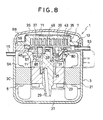
- the scroll compressor which is identified overall as 1 comprises a sealed vessel 3, and a rotation drive device 5 such as a motor and a compression device 7 for compressing gas, which are contained inside the sealed vessel 3.
- the sealed vessel 3 has a cylindrical casing 3C with bottom and a sealing cover 3S which is fixed to the casing 3c so that the vessel is sealed.
- An approximately disc-shaped frame 11 which partitions the interior of the sealed vessel 3 into a drive chamber 9A and a compression device chamber 9B is solidly fixed to the frame 11.
- a connecting hole 13 which connects the drive chamber 9A and the compression device chamber 9B is opened in this frame 11.
- an exhaust tube 15 is formed in the sealed vessel 3 at a location remote from the connecting hole 13.
- the rotation drive device 5 has a motor. Its stator iron core 21 is integrally attached to the casing 3C inside the said drive chamber 9A, and the rotor 23 is integrally attached to the main or rotating shaft 25 which is supported vertically by the center part of the said frame 11 so that it is free to rotate.
- the bottom end of the rotation shaft 25 is immersed inside lubricating oil which collects in the lubricating oil well 27 inside the bottom of the casing 3C.
- the core of this rotation shaft 25 has a lubricating oil suction hole 29, which sucks lubrication oil during rotation, inclined at an appropriate angle to the core of the shaft.
- This suction hole 29 connects to relevant parts such as the frame 11 in order to send lubricating oil to the bearings and to the compression device 7.
- the top end of the rotating shaft 25 has an eccentric section 25E which is displaced an appropriate amount from the center of the rotation shaft 25 formed in it, and a balancer 33 is attached off-center as necessary to balance the eccentric section 25E to minimize
- the compression device 7 is located in the compression device chamber 9B. It comprises the disc-shaped stationary end plate 39 to which the stationary scroll wrap 35 is integrally formed and the disc-shaped orbital end plate 45 to which the orbital scroll wrap 43, which slides against the stationary scroll wrap 35 at a plurality of locations thus forming compression chambers at a plurality of locations, is integrally formed.
- the stationary end plate 39 is sealingly fixed to the frame 11.
- An ejection port 49 through which high-pressure gas that has been compressed is ejected into the compression device chamber 9B is opened in the approximate centers of the stationary end plate 39.
- the suction pipe 53 is connected to the frame 11.
- the stationary scroll wrap 35 and the stationary end plate 39 together form the stationary scroll member; the orbital scroll wrap 43 and the orbital end plate 45 and the mating section 55, which are to be discussed below, together form the orbital scroll member.
- the orbital end plate 45 as shown in Figure 1, is mated with the stationary end plate 39.
- a plurality of compression chambers are formed by the sliding of the orbital scroll wrap 43 against the stationary scroll wrap 35 at a plurality of locations.
- the cylindrically-shaped mating section 55 is formed in the centers of the rear or bottom side of the orbital end plate 45.
- the eccentric section 25E of the rotation shaft 25 is mated to the inside of this mating section 55 so that it is free to rotate.
- the rear surfaces of the plate 45 is supported by the top surface of an annular protrusion formed on the frame 11 so that they are free to rotate.
- the protrusion defines a slidably engaging portion with the mating surface portion of the orbital end plate, and can be formed on the orbital end plate in stead of on the frame.
- a low pressure chamber 59 which is connected to the suction chamber 37 is formed in the outside of the protrusion 57.
- An Oldham's ring 61 is installed within this low pressure chamber 59.
- a cover plate 71 is attached to the stationary end plate 39. It mufflers the sound when high pressure gas is ejected from the ejection port 49, and also prevents high pressure gas from impacting directly on the sealing cover 35.
- the sealed vessel has essentially a lower pressure side or section including the low pressure chamber 59 and a higher pressure side or section exposed to the high pressure gas.
- the Oldham's ring 61 keeps the directionality of the orbital end plate 45 with respect to the stationary end plate 39 fixed at all times.
- a lower protrusion (omitted from the figure) is formed in the lower surface of the Oldham's ring 61, and an upper protrusion (omitted from the figure) at a right angle to the lower protrusion is formed in the upper surface.
- the lower protrusion of this Oldham's ring 61 is coupled to a guide groove formed in the bottom of the low pressure chamber 59 so that it is free to slide, while the upper protrusion is coupled to a guide groove formed in the rear surface of the orbital end plate 45 so that it is free to slide.
- Figure 2 shows the amount of oil injected as the abscissa versus the coefficient of performance of the compressor as the ordinate.
- the amount of oil injected is expressed as the ratio of the actual amount ⁇ 0 of oil injected to the amount ⁇ m of oil injected when the coefficient of performance is a maximum; the coefficient of performance is expressed as the ratio of the actual coefficient of performance C.O.P. to the maximum coefficient of performance C.O.P.max.
- lubricant is supplied to the low pressure section on the rear side or bottom side of the orbital scroll member. Lubricant is then supplied from there to the compression chambers.
- This invention is based on the fact that if the compressor components in the supply path, for example the protrusion and the Oldham's ring, are utilized as means of limiting the flow, then even if a separate means of limiting the flow is not provided, the amount of lubricant supplied will be limited to a desirable level.
- a depression 73 is formed in the frame 11 around the rotation shaft 25.
- a channel or conduit 75 extends from this depression 73 to the upper surface of the protrusion 57 of the frame 11.
- the channel 75 can be installed in a plurality of locations.
- the high-pressure gas which is ejected into the compression device chamber 9B passes through the connecting hole 13 into the drive chamber 9A, specifically the higher pressure side, and is exhausted to the outside from the exhaust tube 15.
- the lubricating oil 27 which has collected in the bottom of the casing 3C is pumped up to the supply port 31 by the rotary pump action of the main shaft 25, lubricates all around the main shaft 25 and collects in the depression 73 in the frame 11.
- the existence of this pressure difference across the protrusion 57 and the movement of the orbital end plate 45 on the upper surface of the protrusion 57 cause the lubricating oil in the depression 73 to be sucked up into the channel 75 and supplied to the low pressure chamber 59 which is on the lower pressure side.
- the eccentric section 25E of the rotation shaft 25 is contained in a space 80, which is communicated with the drive chamber 9A through a hole 85. If the hole 85 were not there, the space 80 would fill up with oil and the supply of oil by the main shaft would not take place, making the lubrication of the sliding surfaces of the main shaft inadequate.
- the hole 85 enables excess oil to return to the bottom of the case, improving the circulation of oil and eliminating the problem of inadequate lubrication.
- the centre-offset balancer 33 rotates in the space 80, if oil is present, it will cause friction loss; the hole 85 eliminates that loss.
- the channel 75 is introduced to a location where it faces the low pressure chamber 59 of the frame 11, connecting the space between the protrusion 57 and the Oldham's ring 61 with the oil well 73, and the pressure difference supplies lubricating oil directly to the low pressure chamber 59.
- the Oldham's ring acts to limit the flow.
- FIG 4 there is a protrusion formed on the orbital scroll end plate and there is a channel 75 which is communicated alternately with the top surface of the protrusion and with the low pressure section as the orbital scroll member rotates.
- the channel 75 can also be made to be open only to either the top surface of the protrusion or the low pressure section.
- a channel 75 communicates the Oldham's ring key side surface with a frame oil well.
- the reciprocating motion of the key controls the amount of oil supplied, and an appropriate amount of oil is injected. This also improves the lubrication of the key. It is also possible to have channels connecting to plurality of locations on the side surface of the key.
- a channel 75 communicates the frame sliding part of the Oldham's ring to the frame oil well.
- the reciprocating motion of the Oldham's ring controls the amount of oil supplied, so that an appropriate amount of oil can be injected. In addition, this improves the lubrication of the Oldham's ring in the thrust direction at the sliding section. It is also possible to connect to a plurality of locations below the Oldham's ring.
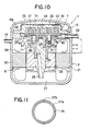
- annular groove 57a is cut in the protrusion 57 as shown in Figure 11.
- a channel 75 connects to this annular groove.
- One or more ejection grooves 57b are cut in the radial direction from this annular groove so that lubricant is sent to the lower pressure side.
- compressor components on the rear side of the orbital scroll member are used as means to control the flow of lubricant.
- lubricating oil can be supplied stably to the spaces between the orbital scroll member and the stationary scroll member, improving both sealing and capacity while maintaining adequate lubrication.
Landscapes
- Engineering & Computer Science (AREA)
- Mechanical Engineering (AREA)
- General Engineering & Computer Science (AREA)
- Rotary Pumps (AREA)
Applications Claiming Priority (2)
| Application Number | Priority Date | Filing Date | Title |
|---|---|---|---|
| JP60214954A JPS6275091A (ja) | 1985-09-30 | 1985-09-30 | スクロ−ルコンプレツサ |
| JP214954/85 | 1985-09-30 |
Publications (3)
| Publication Number | Publication Date |
|---|---|
| EP0217349A2 true EP0217349A2 (de) | 1987-04-08 |
| EP0217349A3 EP0217349A3 (en) | 1988-09-14 |
| EP0217349B1 EP0217349B1 (de) | 1992-08-19 |
Family
ID=16664314
Family Applications (1)
| Application Number | Title | Priority Date | Filing Date |
|---|---|---|---|
| EP86113401A Expired EP0217349B1 (de) | 1985-09-30 | 1986-09-30 | Spiralkompressor |
Country Status (5)
| Country | Link |
|---|---|
| US (1) | US4762477A (de) |
| EP (1) | EP0217349B1 (de) |
| JP (1) | JPS6275091A (de) |
| DE (1) | DE3686464T2 (de) |
| DK (1) | DK463786A (de) |
Cited By (5)
| Publication number | Priority date | Publication date | Assignee | Title |
|---|---|---|---|---|
| FR2668550A1 (fr) * | 1990-10-29 | 1992-04-30 | American Standard Inc | Appareil et compresseur a volutes et systeme de refrigeration les utilisant. |
| EP0518356A1 (de) * | 1991-06-13 | 1992-12-16 | Daikin Industries, Limited | Strömungsmaschine in Spiralbauweise |
| GB2249353B (en) * | 1990-10-29 | 1994-05-18 | American Standard Inc | Co-rotational scroll apparatus with positive lubricant flow |
| EP0657650A1 (de) * | 1993-11-03 | 1995-06-14 | Copeland Corporation | Ölzuführsystem für einen Spiralverdichter |
| EP2940302A4 (de) * | 2012-12-28 | 2016-08-24 | Daikin Ind Ltd | Spiralverdichter |
Families Citing this family (16)
| Publication number | Priority date | Publication date | Assignee | Title |
|---|---|---|---|---|
| US5219281A (en) * | 1986-08-22 | 1993-06-15 | Copeland Corporation | Fluid compressor with liquid separating baffle overlying the inlet port |
| US4993927A (en) * | 1988-06-03 | 1991-02-19 | Mitsubishi Denki Kabushiki Kaisha | Scroll fluid machine with lubrication of oldham coupling |
| US4904165A (en) * | 1988-08-02 | 1990-02-27 | Carrier Corporation | Muffler/check valve assembly for scroll compressor |
| US4993929A (en) * | 1989-10-04 | 1991-02-19 | Copeland Corporation | Scroll machine with lubricated thrust surfaces |
| US5306126A (en) * | 1991-03-27 | 1994-04-26 | Tecumseh Products Company | Scroll compressor lubrication control |
| US5131828A (en) * | 1991-03-27 | 1992-07-21 | Tecumseh Products Company | Scroll compressor including compliance mechanism for the orbiting scroll member |
| US5842420A (en) * | 1992-09-07 | 1998-12-01 | Khoo; Chew Thong | Crankshaft lubrication system |
| BR9300797A (pt) * | 1993-03-02 | 1994-10-04 | Brasil Compressores Sa | Bomba de óleo para compressor hermético de velocidade variável |
| US6017205A (en) * | 1996-08-02 | 2000-01-25 | Copeland Corporation | Scroll compressor |
| JP2000179460A (ja) * | 1998-12-15 | 2000-06-27 | Denso Corp | 圧縮機 |
| DE10213252B4 (de) * | 2001-03-26 | 2013-11-28 | Kabushiki Kaisha Toyota Jidoshokki | Elektrisch angetriebene Kompressoren und Verfahren zum Umlaufenlassen von Schmieröl durch diese Kompressoren |
| KR100924895B1 (ko) | 2002-05-24 | 2009-11-02 | 파나소닉 주식회사 | 스크롤 압축기 |
| US7044717B2 (en) | 2002-06-11 | 2006-05-16 | Tecumseh Products Company | Lubrication of a hermetic carbon dioxide compressor |
| US20050207926A1 (en) * | 2002-09-24 | 2005-09-22 | Matsushita Electric Industrial Co., Ltd. | Scroll compressor |
| JP2008501080A (ja) * | 2004-05-28 | 2008-01-17 | 松下電器産業株式会社 | 密閉型圧縮機 |
| AU2005327258B2 (en) * | 2005-02-07 | 2011-03-24 | Carrier Corporation | Screw compressor lubrication |
Family Cites Families (10)
| Publication number | Priority date | Publication date | Assignee | Title |
|---|---|---|---|---|
| JPS5685087A (en) * | 1979-12-10 | 1981-07-10 | Hiroshi Watanabe | Enlarged auger head for core drilling method |
| US4431388A (en) * | 1982-03-05 | 1984-02-14 | The Trane Company | Controlled suction unloading in a scroll compressor |
| JPS58160582A (ja) * | 1982-03-19 | 1983-09-24 | Hitachi Ltd | スクロ−ル圧縮機 |
| JPS58214692A (ja) * | 1982-06-07 | 1983-12-13 | Mitsubishi Electric Corp | スクロ−ル圧縮機 |
| JPS5993987A (ja) * | 1982-11-19 | 1984-05-30 | Hitachi Ltd | スクロ−ル流体機械 |
| JPS59110893A (ja) * | 1982-12-17 | 1984-06-26 | Hitachi Ltd | スクロ−ル形流体機械 |
| JPS59119090A (ja) * | 1982-12-24 | 1984-07-10 | Hitachi Ltd | スクロ−ル圧縮機 |
| US4522575A (en) * | 1984-02-21 | 1985-06-11 | American Standard Inc. | Scroll machine using discharge pressure for axial sealing |
| JPS60192894A (ja) * | 1984-03-13 | 1985-10-01 | Mitsubishi Electric Corp | スクロ−ル圧縮機 |
| JPS6128782A (ja) * | 1984-07-20 | 1986-02-08 | Toshiba Corp | スクロ−ルコンプレツサ |
-
1985
- 1985-09-30 JP JP60214954A patent/JPS6275091A/ja active Pending
-
1986
- 1986-09-29 DK DK463786A patent/DK463786A/da not_active Application Discontinuation
- 1986-09-30 US US06/913,349 patent/US4762477A/en not_active Expired - Fee Related
- 1986-09-30 DE DE8686113401T patent/DE3686464T2/de not_active Expired - Fee Related
- 1986-09-30 EP EP86113401A patent/EP0217349B1/de not_active Expired
Cited By (7)
| Publication number | Priority date | Publication date | Assignee | Title |
|---|---|---|---|---|
| FR2668550A1 (fr) * | 1990-10-29 | 1992-04-30 | American Standard Inc | Appareil et compresseur a volutes et systeme de refrigeration les utilisant. |
| GB2249353B (en) * | 1990-10-29 | 1994-05-18 | American Standard Inc | Co-rotational scroll apparatus with positive lubricant flow |
| GB2249351B (en) * | 1990-10-29 | 1994-05-25 | American Standard Inc | Scroll apparatus with enhanced lubricant flow |
| EP0518356A1 (de) * | 1991-06-13 | 1992-12-16 | Daikin Industries, Limited | Strömungsmaschine in Spiralbauweise |
| US5249941A (en) * | 1991-06-13 | 1993-10-05 | Daikin Industries, Ltd. | Scroll type fluid machine having intermittent oil feed to working chamber |
| EP0657650A1 (de) * | 1993-11-03 | 1995-06-14 | Copeland Corporation | Ölzuführsystem für einen Spiralverdichter |
| EP2940302A4 (de) * | 2012-12-28 | 2016-08-24 | Daikin Ind Ltd | Spiralverdichter |
Also Published As
| Publication number | Publication date |
|---|---|
| EP0217349A3 (en) | 1988-09-14 |
| DE3686464T2 (de) | 1993-02-18 |
| US4762477A (en) | 1988-08-09 |
| DK463786A (da) | 1987-03-31 |
| DE3686464D1 (de) | 1992-09-24 |
| EP0217349B1 (de) | 1992-08-19 |
| DK463786D0 (da) | 1986-09-29 |
| JPS6275091A (ja) | 1987-04-06 |
Similar Documents
| Publication | Publication Date | Title |
|---|---|---|
| US4762477A (en) | Scroll compressor with control of lubricant flow | |
| US4708607A (en) | Scroll compressor with lower and higher pressure chambers acting on the orbiting end plate | |
| KR101467577B1 (ko) | 압축기 | |
| EP2689137B1 (de) | Spiralverdichter | |
| KR100452837B1 (ko) | 스크롤압축기 | |
| JP3335656B2 (ja) | 横置形圧縮機 | |
| US11248608B2 (en) | Compressor having centrifugation and differential pressure structure for oil supplying | |
| JP5655850B2 (ja) | スクロール型圧縮機 | |
| JPS62101895A (ja) | 羽根スロツト圧力溝を有する回転コンプレツサ− | |
| US6637550B2 (en) | Displacement type fluid machine | |
| KR100724387B1 (ko) | 밀폐형 압축기의 오일 펌핑 장치 | |
| KR20050026875A (ko) | 스크롤 압축기 | |
| EP0683321B1 (de) | Schwingender rotations-kompressor | |
| CN116857189A (zh) | 具有轴向柔性的压缩机 | |
| CN215521261U (zh) | 旋转式压缩机 | |
| KR20180101901A (ko) | 스크롤 압축기 | |
| US6338617B1 (en) | Helical-blade fluid machine | |
| KR102392655B1 (ko) | 냉매의 토출 유로와 오일 회수 유로를 분리한 압축기 | |
| KR20060051788A (ko) | 압축기 | |
| EP1643127A2 (de) | Verdichter | |
| EP0502514A1 (de) | Spiralverdichter mit verbesserter Schmierungsanlage dessen bewegender Teile | |
| US5221199A (en) | Lubrication oil volume control device in a scroll type compressor | |
| JP2009062820A (ja) | 密閉形ロータリ圧縮機 | |
| CN213511190U (zh) | 一种轴承座及其卧式涡旋压缩机 | |
| KR100620999B1 (ko) | 고압식 스크롤 압축기의 유토출 저감 장치 |
Legal Events
| Date | Code | Title | Description |
|---|---|---|---|
| PUAI | Public reference made under article 153(3) epc to a published international application that has entered the european phase |
Free format text: ORIGINAL CODE: 0009012 |
|
| 17P | Request for examination filed |
Effective date: 19860930 |
|
| AK | Designated contracting states |
Kind code of ref document: A2 Designated state(s): DE FR GB |
|
| PUAL | Search report despatched |
Free format text: ORIGINAL CODE: 0009013 |
|
| AK | Designated contracting states |
Kind code of ref document: A3 Designated state(s): DE FR GB |
|
| 17Q | First examination report despatched |
Effective date: 19890608 |
|
| GRAA | (expected) grant |
Free format text: ORIGINAL CODE: 0009210 |
|
| AK | Designated contracting states |
Kind code of ref document: B1 Designated state(s): DE FR GB |
|
| REF | Corresponds to: |
Ref document number: 3686464 Country of ref document: DE Date of ref document: 19920924 |
|
| ET | Fr: translation filed | ||
| PLBE | No opposition filed within time limit |
Free format text: ORIGINAL CODE: 0009261 |
|
| STAA | Information on the status of an ep patent application or granted ep patent |
Free format text: STATUS: NO OPPOSITION FILED WITHIN TIME LIMIT |
|
| 26N | No opposition filed | ||
| PGFP | Annual fee paid to national office [announced via postgrant information from national office to epo] |
Ref country code: GB Payment date: 19940920 Year of fee payment: 9 |
|
| PGFP | Annual fee paid to national office [announced via postgrant information from national office to epo] |
Ref country code: DE Payment date: 19940921 Year of fee payment: 9 |
|
| PGFP | Annual fee paid to national office [announced via postgrant information from national office to epo] |
Ref country code: FR Payment date: 19950911 Year of fee payment: 10 |
|
| PG25 | Lapsed in a contracting state [announced via postgrant information from national office to epo] |
Ref country code: GB Effective date: 19950930 |
|
| GBPC | Gb: european patent ceased through non-payment of renewal fee |
Effective date: 19950930 |
|
| PG25 | Lapsed in a contracting state [announced via postgrant information from national office to epo] |
Ref country code: DE Effective date: 19960601 |
|
| PG25 | Lapsed in a contracting state [announced via postgrant information from national office to epo] |
Ref country code: FR Effective date: 19960930 |
|
| REG | Reference to a national code |
Ref country code: FR Ref legal event code: ST |
|
| REG | Reference to a national code |
Ref country code: FR Ref legal event code: ST |