EP0657650A1 - Ölzuführsystem für einen Spiralverdichter - Google Patents
Ölzuführsystem für einen Spiralverdichter Download PDFInfo
- Publication number
- EP0657650A1 EP0657650A1 EP94307921A EP94307921A EP0657650A1 EP 0657650 A1 EP0657650 A1 EP 0657650A1 EP 94307921 A EP94307921 A EP 94307921A EP 94307921 A EP94307921 A EP 94307921A EP 0657650 A1 EP0657650 A1 EP 0657650A1
- Authority
- EP
- European Patent Office
- Prior art keywords
- scroll
- passage
- bearing housing
- chamber
- Prior art date
- Legal status (The legal status is an assumption and is not a legal conclusion. Google has not performed a legal analysis and makes no representation as to the accuracy of the status listed.)
- Granted
Links
- 239000010725 compressor oil Substances 0.000 title abstract 2
- 239000000314 lubricant Substances 0.000 claims abstract description 15
- 239000012530 fluid Substances 0.000 claims description 21
- 238000004891 communication Methods 0.000 claims description 12
- 239000003921 oil Substances 0.000 abstract description 73
- 239000010687 lubricating oil Substances 0.000 abstract description 41
- 238000005461 lubrication Methods 0.000 abstract description 17
- 230000006835 compression Effects 0.000 abstract description 12
- 238000007906 compression Methods 0.000 abstract description 12
- 238000001816 cooling Methods 0.000 abstract description 4
- 230000001050 lubricating effect Effects 0.000 description 7
- 230000008878 coupling Effects 0.000 description 6
- 238000010168 coupling process Methods 0.000 description 6
- 238000005859 coupling reaction Methods 0.000 description 6
- 238000005086 pumping Methods 0.000 description 5
- 238000000034 method Methods 0.000 description 4
- 238000005192 partition Methods 0.000 description 3
- 230000009471 action Effects 0.000 description 2
- 230000000694 effects Effects 0.000 description 2
- 230000009467 reduction Effects 0.000 description 2
- 239000003507 refrigerant Substances 0.000 description 2
- 230000004075 alteration Effects 0.000 description 1
- 230000015572 biosynthetic process Effects 0.000 description 1
- 238000010276 construction Methods 0.000 description 1
- 230000001419 dependent effect Effects 0.000 description 1
- 238000013461 design Methods 0.000 description 1
- 238000007667 floating Methods 0.000 description 1
- 230000005484 gravity Effects 0.000 description 1
- 238000010348 incorporation Methods 0.000 description 1
- 238000002347 injection Methods 0.000 description 1
- 239000007924 injection Substances 0.000 description 1
- 230000007246 mechanism Effects 0.000 description 1
- 239000003595 mist Substances 0.000 description 1
- 230000004048 modification Effects 0.000 description 1
- 238000012986 modification Methods 0.000 description 1
- 230000008569 process Effects 0.000 description 1
- 238000013022 venting Methods 0.000 description 1
- 238000004804 winding Methods 0.000 description 1
Images


Classifications
-
- F—MECHANICAL ENGINEERING; LIGHTING; HEATING; WEAPONS; BLASTING
- F04—POSITIVE - DISPLACEMENT MACHINES FOR LIQUIDS; PUMPS FOR LIQUIDS OR ELASTIC FLUIDS
- F04C—ROTARY-PISTON, OR OSCILLATING-PISTON, POSITIVE-DISPLACEMENT MACHINES FOR LIQUIDS; ROTARY-PISTON, OR OSCILLATING-PISTON, POSITIVE-DISPLACEMENT PUMPS
- F04C29/00—Component parts, details or accessories of pumps or pumping installations, not provided for in groups F04C18/00 - F04C28/00
- F04C29/0007—Injection of a fluid in the working chamber for sealing, cooling and lubricating
-
- F—MECHANICAL ENGINEERING; LIGHTING; HEATING; WEAPONS; BLASTING
- F04—POSITIVE - DISPLACEMENT MACHINES FOR LIQUIDS; PUMPS FOR LIQUIDS OR ELASTIC FLUIDS
- F04C—ROTARY-PISTON, OR OSCILLATING-PISTON, POSITIVE-DISPLACEMENT MACHINES FOR LIQUIDS; ROTARY-PISTON, OR OSCILLATING-PISTON, POSITIVE-DISPLACEMENT PUMPS
- F04C18/00—Rotary-piston pumps specially adapted for elastic fluids
- F04C18/02—Rotary-piston pumps specially adapted for elastic fluids of arcuate-engagement type, i.e. with circular translatory movement of co-operating members, each member having the same number of teeth or tooth-equivalents
- F04C18/0207—Rotary-piston pumps specially adapted for elastic fluids of arcuate-engagement type, i.e. with circular translatory movement of co-operating members, each member having the same number of teeth or tooth-equivalents both members having co-operating elements in spiral form
- F04C18/0215—Rotary-piston pumps specially adapted for elastic fluids of arcuate-engagement type, i.e. with circular translatory movement of co-operating members, each member having the same number of teeth or tooth-equivalents both members having co-operating elements in spiral form where only one member is moving
-
- F—MECHANICAL ENGINEERING; LIGHTING; HEATING; WEAPONS; BLASTING
- F04—POSITIVE - DISPLACEMENT MACHINES FOR LIQUIDS; PUMPS FOR LIQUIDS OR ELASTIC FLUIDS
- F04C—ROTARY-PISTON, OR OSCILLATING-PISTON, POSITIVE-DISPLACEMENT MACHINES FOR LIQUIDS; ROTARY-PISTON, OR OSCILLATING-PISTON, POSITIVE-DISPLACEMENT PUMPS
- F04C2240/00—Components
- F04C2240/80—Other components
- F04C2240/807—Balance weight, counterweight
Definitions
- the present invention generally relates to scroll-type machinery. More particularly, the present invention relates to an improved lubricating system for scroll compressors which controls the oil circulation rate throughout the operating envelope of the compressor.
- Scroll machinery for fluid compression or expansion is typically comprised of two upstanding interfitting involute spirodal wraps or scrolls which are generated about respective axes.
- Each respective scroll is mounted upon an end plate and has a tip disposed in contact or near contact with the end plate of the other respective scroll.
- Each scroll further has flank surfaces which adjoin, in moving line contact or near contact, the flank surfaces of the other respective scroll to form a plurality of moving chambers.
- the chambers move from the radially exterior ends of the scrolls to the radially interior ends of the scrolls for fluid compression, or from the radially interior ends of the scrolls to the radially exterior ends of the scrolls for fluid expansion.
- the scrolls, to accomplish the formation of the chambers are put in relative orbital motion by a drive mechanism. Either one of the scrolls may orbit or both may rotate eccentrically with respect to one another.
- a typical scroll machine includes an orbiting scroll which meshes with the non-orbiting scroll, a thrust bearing to take the axial loads on the orbiting scroll, and a lubricant supply system for lubricating the various moving components of the machine including the thrust bearing. Accordingly, there is a continuous need in the field of scroll machines for improved lubricating techniques throughout the operating range of the machinery.
- suction gas flow which is allowed to pick up the overspray of lubricant oil from the compressor's components and circulate it throughout the compressor.
- Suction gas is baffled and routed through the compressor in such a way as to control the amount of oil which is picked up by the suction gas to a tolerable level for compressor operation at rated operating conditions.
- the oil circulation rate is actually lower. This lower oil circulation rate is the result of the suction gas being much less dense at the higher compression ratios and therefore the suction gas does not entrain as much of the oil overspray.
- the lubrication system of the present invention can provide a constant oil circulation rate over the entire operating envelope of the compressor or the present invention can be adapted to provide a nominal oil circulation rate at cooler oil temperatures and a selectively higher oil circulation rate at higher oil temperatures if desired.
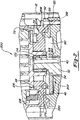
- FIG. 1 a vertical sectional view of a scroll compressor 10 incorporating the lubrication system according to the present invention.
- compressor 10 comprises a generally cylindrical hermetic shell 12 having welded at the upper end thereof a cap 14.
- Cap 14 is provided with a refrigerant discharge fitting 16 optionally having the usual discharge valve therein (not shown).
- cylindrical shell 12 Other elements affixed to cylindrical shell 12 include a transversely extending partition 18 which is welded about its periphery at the same point cap 14 is welded to shell 12, a lower bearing housing 20 which is affixed to shell 12 at a plurality of points by methods known well in the art, and a suction gas inlet fitting 22.
- Lower bearing housing 20 locates and supports within shell 12 a main bearing housing 24, a motor stator 26, a lower bearing 28 and a non-orbiting scroll member 30.
- a crankshaft 32 having an eccentric crank pin 34 at the upper end thereof is rotatably journaled in lower bearing 28 in lower bearing housing 20 and in an upper bearing 36 in main bearing housing 24.
- Crankshaft 32 has at its lower end the usual relatively large diameter oil-pumping concentric bore 38 which communicates with a smaller diameter bore 40 extending upwardly therefrom to the top of crankshaft 32.
- the lower portion of cylindrical shell 12 is filled with lubricating oil in the usual manner and the pump of bore 38 at the bottom of the crankshaft 32 is the primary pump acting in conjunction with bore 40 to pump lubricating fluid to all the various portions of the compressor which require lubrication as will be described later herein.
- Crankshaft 32 is rotatably driven by an electric motor including motor stator 26 having motor windings 42 passing therethrough, and a motor rotor 44 press fit on crankshaft 32 and having a lower counterweight 46 and an upper counterweight 48.
- Main bearing housing 24 includes a bearing cage 50 and an upper bearing housing 52.
- Bearing cage 50 has a generally cylindrical shaped central portion 54 within which the upper end of crankshaft 32 is rotatably supported by means of bearing 36.
- An upstanding annular projection 56 is provided on bearing cage 50 adjacent the outer periphery of central portion 54 and includes an accurately machined radially outwardly facing surface 58, an accurately machined radially inwardly facing surface 59 and an upwardly facing locating surface 60.
- a plurality of radially circumferentially spaced supporting arms 62 extend generally radially outwardly from central portion 54 and include axially extending portions adapted to engage and be supported on lower bearing housing 20.
- a step 64 is provided on the terminal end of the axially extending portion of each of the supporting arms 62 for engaging lower bearing housing 20.
- Step 64 is designed to mate with a corresponding recess provided on the abutting portion of lower bearing housing 20 for aiding in radially positioned bearing cage 50 with respect to lower bearing housing 20.
- Upper bearing housing 52 of main bearing housing 24 is generally cup-shaped including an upper annular guide ring portion 66 integrally formed therewith, an annular axial thrust bearing surface 68 disposed below ring portion 66, and a second annular supporting bearing surface 70 positioned below and in radially outwardly surrounding relationship to axial thrust bearing surface 68.
- Axial thrust bearing surface 68 serves to axially movably support an orbiting scroll member 72, and supporting bearing surface 70 provides support for an Oldham coupling 74.
- upper bearing housing 52 includes an annular recess defining radially inwardly and axially downwardly facing surfaces 76 and 78 respectively which are designed to mate with surfaces 58 and 60 respectively of bearing cage 50 to aid in axially and radially positioning upper bearing housing 52 and bearing cage 50 relative to each other.
- a cavity 80 is designed to accommodate rotational movement of upper counterweight 48 secured to crankshaft 32 at the upper end thereof. The provision of this cavity enables counterweight 48 to be positioned in closer proximity to orbiting scroll member 72 thus enabling the overall size thereof to be reduced.
- counterweight 48 rotating within cavity 80 creates a counterweight pump which provides an oil pumping action for lubricating a portion of compressor 10 as will be described later herein.
- Annular integrally formed guide ring 66 is positioned in surrounding relationship to a radially outwardly extending flange portion 84 of non-orbiting scroll member 30 and includes a radially inwardly facing surface 86 adapted to abut a radially outwardly facing surface 88 of flange portion 84 so as to radially position and guide axial movement of non-orbiting scroll member 30.
- Non-orbiting scroll member 30 has a centrally disposed discharge passageway 94 communicating with an upwardly open recess 96 which is in fluid communication via an opening 98 in partition 18 with a discharge muffler chamber 100 defined by cap 14 and partition 18.
- Non-orbiting scroll member 30 further has in the upper surface thereof an annular recess 102 having parallel coaxial side walls in which is sealingly disposed for relative axial movement an annular floating seal 104 which serves to isolate the bottom of recess 102 from the presence of gas under suction and discharge pressure so that it can be placed in fluid communication with a source of intermediate fluid pressure by means of a passageway (not shown).
- Non-orbiting scroll member 30 is thus axially biased against orbiting scroll member 72 by the forces created by discharge pressure acting on the central portion of non-orbiting scroll member 30 and those created by intermediate fluid pressure acting on the bottom of recess 102.
- This axial pressure biasing, as well as other various techniques for supporting scroll member 30 for limited axial movement, are disclosed in much greater detail in assignee's U.S. Letters Patent No. 4,877,382, the disclosure of which is hereby incorporated herein by reference.
- the compressor is preferably of the "low side" type in which suction gas entering via gas inlet 22 is allowed, in part, to escape into shell 12 and assist in cooling the motor. So long as there is an adequate flow of returning suction gas, the motor will remain within desired temperature limits. When this flow drops significantly, however, the loss of cooling will eventually cause a temperature sensor to signal the control device to shut the machine down.
- Lubrication system 200 deals with the lubrication of the thrust bearing surface 68, venting of the lubrication system to improve reliability and the injection of a small amount of lubricating oil into the gaseous refrigerant just prior to compression to increase efficiency and reduce noise.
- the lubrication system for compressor 10 begins in the lower portion of cylindrical shell 12 which is filled with lubrication oil in the usual manner.
- Bore 38 at the bottom of crankshaft 32 is the primary pump acting in conjunction with bore 40 to pump lubricating fluid to all the various portions of the compressor which require lubrication.
- a cross bore 154 extending through crankshaft 32 to bore 38 serves to provide lubricating oil to lower bearing 28.
- a flat (not shown) is provided on the exterior of crankshaft 32 to assist in the distribution of lubricating oil to lower bearing 28.
- a second cross bore 158 extends through crankshaft 32 to bore 40. Cross bore 158 serves to provide lubricating oil to upper bearing 36.
- a flat 160 is provided on the exterior surface of crankshaft 32 to assist in the distribution of lubricating oil to upper bearing 36.
- Lubricating oil that is pumped through cross bore 158 to upper bearing 36 flows around upper bearing 36 with a first portion returning to the lower portion of shell 12 and a second portion being discharged into cavity 80.
- the remainder of lubricating oil being pumped through bores 38 and 40 exits bore 40 at the top of crankshaft 32 to lubricate a drive bearing 162 located on eccentric crankpin 34 and an unloader bushing 164.
- a drive flat 172 on crankshaft 32 is provided with lubricating oil by a bleed hole 174 extending through unloader bushing 164.
- lubricating oil will flow through the recess between unloader bushing 164 and crankshaft 32 in order to adequately lubricate unloader bushing 164.
- Lubricating oil and evolved gas are discharged from the area surrounding crank pin 74 into cavity 80.
- Lubrication system 200 utilizes the rotational movement of upper counterweight 48 within cavity 80 as an impeller to function as a counterweight pump 202 to pump lubricating oil to the upper scroll portion of compressor 10.
- Inwardly facing surface 59 of bearing cage 50 is dimensioned slightly larger than the swing diameter of upper counterweight 48. This close relationship between counterweight 48 and inwardly facing wall 59 creates a strong potential centrifugal pumping effect upon the rotation of counterweight 48, thus creating counterweight pump 202.
- Counterweight pump 202 creates an oil head which takes lubricating oil and suction gas from the interior of shell 12 and creates a strong vortex flow along inwardly facing wall 59 of bearing cage 50. The oil head which is produced causes the lubricating oil to climb wall 59.
- a portion of the circular oil flow goes into a milled groove 176 located within upper bearing housing 52 which curves radially inward. Groove 176 ends abruptly and lubricating oil proceeds up a vertically positioned oil circulation feed hole 210 also located within upper bearing housing 52 under its own velocity head.
- An oil circulation control hole 216 extends through orbiting scroll 72 and receives lubricating oil from oil circulation feed hole 210 as will be described later herein.
- Second annular supporting bearing surface 70 of upper bearing housing 52 of main bearing housing 24 has an annular oil groove 218 cut into it.
- Oil groove 218 collects the lubricating oil discharge off of bearing thrust surface 68 and operates to supply lubricating oil to Oldham coupling 74.
- Two angularly drilled oil discharge holes 220 are machined from the exterior of upper bearing housing 52 of main bearing housing 24 to a point which intersects with annular oil groove 218. Thus any oil accumulating within annular oil groove 218 is drained off under the force of gravity to the lower portion of shell 12 through the two oil discharge holes 220.
- the lubrication system operates to provide continuous supply of lubricating oil to the lower bearing 28, upper bearing 36, drive bearing 162, unloader 164, scroll thrust bearing surfaces 68 and 70, Oldham coupling 74 and the scroll oil circulation control system through oil circulation control hole 216.
- the lubricating oil begins in the sump or lower portion of shell 12 and oil is pumped up bore 38 and bore 40 to exit the top of crankshaft 32. As the lubricating oil moves up bores 38 and 40, some of the lubricating oil is directed through cross bore 154 to lower bearing 28 and through cross bore 158 to upper bearing 36. Upon exiting the top end of crankshaft 32 the lubricating oil lubricates drive bearing 162 and unloader bushing 164.
- Lubricating oil from upper bearing 36 and from the top end of crankshaft 32 accumulates in cavity 80.
- Upper counterweight 48 rotates within cavity 80 and pumps a portion of the oil within cavity 80 into milled groove 176 as well as into milled groove 204.
- the portion of lubricating oil pumped into milled groove 204 proceeds into discharge hole 206 and is returned to the sump through oil discharge hole 212 as detailed above.
- the portion of lubricating oil pumped into milled groove 176 proceeds up through oil circulation feed hole 210 to provide lubricating oil to the scroll oil circulation control system including oil circulation control hole 216.
- a portion of the lubricating oil pumped into milled groove 176 will overflow groove 176 and is splashed upon the thrust surface of orbiting scroll 72 by upper counterweight 48. This splash lube is transferred onto thrust bearing surface 68 by the orbiting motion of orbiting scroll 72. A sufficient amount of lubricating oil is provided to maintain the required amount of lubricating oil on thrust bearing surface 68.
- the lubricating oil that is supplied to the scroll oil circulation system is a timed event.
- Oil circulation control hole 216, milled groove 176, and oil circulation feed hole 210 are circumferentially positioned such that as the outermost scroll inlet compressor chamber is opening, the leading edge of upper counterweight 48 passes by milled groove 176 and oil circulation feed hole 210 pumping lubricating oil through oil circulation feed hole 210.
- control hole 216 is positioned to orbit directly over oil circulation feed hole 210 and thus lubricating oil flows up oil circulation feed hole 210 into control hole 216 and into the open outermost scroll inlet compression chamber.
- Oil circulation control system ensures that the oil circulation rate is always controllable, regardless of where compressor 10 is operating in its envelope.
- Oil circulation rate becomes a selective feature by varying the size and shape of oil circulation control hole 216.
- the oil flow rate can be held constant over the operating envelope of the compressor (Option #1) or the oil flow rate can increase when the compressor is operating at higher temperatures (Option #2).
- Option #1 when the outermost scroll inlet compression chamber opens, suction gas flow begins as suction gas enters through the opening.
- Control hole 216 is located at the inlet adjacent to the beginning of the open compression chamber.
- control hole 216 is positioned directly over oil circulation feed hole 210, a quantity of lubricating oil is pumped through control hole 216 and into the open compression chamber.
- the amount of lubricating oil pumped through control hole 216 can be selected by varying the size and shape of control hole 216.
- ⁇ P hole K P o Q o 2 2 + M o Q o 1 d4
- KP o Q o 2/2 is the orifice loss
- M o Q o 1/d4 is the viscous loss.
- P o is equal to the oil density
- Q o is equal to the flow rate
- M o is equal to the oil viscosity
- K is equal to the loss coefficient of the orifice
- 1 is equal to the length of control hole 216
- d is equal to the diameter of control hole 216.
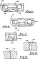
- the rate of oil circulation when compressor 10 is operating at mid-range is considered to be the baseline. Mid-range operation of the compressor is close to ARI conditions. If it is desired to maintain a fairly uniform oil circulation rate across the envelope of operation, an orifice type hole for control hole 216 as shown in Figure 8 is selected. This type of control hole means that the primary loss through control hole 216 will be from the orifice loss term and not the viscous loss term in the equation above. Thus, the oil circulation rate is held fairly uniform, the rate being little affected by the viscous loss. If it is desire to have an increased oil circulation rate at higher operating temperatures, a long and narrow hole for control hole 216 as shown in Figure 9 is selected.
- the long and narrow control hole 216 makes viscous loss the primary factor in determining the oil circulation rate and this factor is highly dependent upon the lubricating oil temperature. Either high temperature at HCR conditions or more suction gas can both serve to lower the viscosity of the lubricating oil and thus increase the flow of oil. Thus, a higher oil circulation rate is provided at a higher operating condition of compressor 10.
Landscapes
- Engineering & Computer Science (AREA)
- Mechanical Engineering (AREA)
- General Engineering & Computer Science (AREA)
- Rotary Pumps (AREA)
- Applications Or Details Of Rotary Compressors (AREA)
Applications Claiming Priority (2)
| Application Number | Priority Date | Filing Date | Title |
|---|---|---|---|
| US147115 | 1993-11-03 | ||
| US08/147,115 US5370513A (en) | 1993-11-03 | 1993-11-03 | Scroll compressor oil circulation system |
Publications (2)
| Publication Number | Publication Date |
|---|---|
| EP0657650A1 true EP0657650A1 (de) | 1995-06-14 |
| EP0657650B1 EP0657650B1 (de) | 1998-04-08 |
Family
ID=22520341
Family Applications (1)
| Application Number | Title | Priority Date | Filing Date |
|---|---|---|---|
| EP94307921A Expired - Lifetime EP0657650B1 (de) | 1993-11-03 | 1994-10-27 | Ölzuführsystem für einen Spiralverdichter |
Country Status (6)
| Country | Link |
|---|---|
| US (1) | US5370513A (de) |
| EP (1) | EP0657650B1 (de) |
| JP (1) | JP4021946B2 (de) |
| KR (1) | KR100294429B1 (de) |
| CN (1) | CN1107555A (de) |
| DE (1) | DE69409474T2 (de) |
Cited By (1)
| Publication number | Priority date | Publication date | Assignee | Title |
|---|---|---|---|---|
| GB2371089B (en) * | 1999-10-01 | 2005-04-13 | Scroll Tech | Reduced height sealed compressor and incorporation of suction tube |
Families Citing this family (59)
| Publication number | Priority date | Publication date | Assignee | Title |
|---|---|---|---|---|
| JP3564769B2 (ja) * | 1995-01-23 | 2004-09-15 | 松下電器産業株式会社 | スクロール圧縮機 |
| US5580401A (en) * | 1995-03-14 | 1996-12-03 | Copeland Corporation | Gray cast iron system for scroll machines |
| JPH09151866A (ja) * | 1995-11-30 | 1997-06-10 | Sanyo Electric Co Ltd | スクロール圧縮機 |
| US5755271A (en) * | 1995-12-28 | 1998-05-26 | Copeland Corporation | Method for casting a scroll |
| US8799100B2 (en) | 1997-07-08 | 2014-08-05 | Groupon, Inc. | Retail system for selling products based on a flexible product description |
| US7711604B1 (en) | 1997-07-08 | 2010-05-04 | Walker Digital, Llc | Retail system for selling products based on a flexible product description |
| US6139295A (en) * | 1998-06-22 | 2000-10-31 | Tecumseh Products Company | Bearing lubrication system for a scroll compressor |
| US6149413A (en) * | 1998-07-13 | 2000-11-21 | Carrier Corporation | Scroll compressor with lubrication of seals in back pressure chamber |
| US6350111B1 (en) * | 2000-08-15 | 2002-02-26 | Copeland Corporation | Scroll machine with ported orbiting scroll member |
| US6374621B1 (en) | 2000-08-24 | 2002-04-23 | Cincinnati Sub-Zero Products, Inc. | Refrigeration system with a scroll compressor |
| JP3982238B2 (ja) * | 2001-11-08 | 2007-09-26 | 三菱電機株式会社 | 圧縮機 |
| JP3843333B2 (ja) * | 2002-09-11 | 2006-11-08 | 株式会社日立製作所 | スクロール流体機械 |
| US7179069B2 (en) * | 2004-08-25 | 2007-02-20 | Copeland Corporation | Motor compressor lubrication |
| KR100679886B1 (ko) | 2004-10-06 | 2007-02-08 | 엘지전자 주식회사 | 급유 기능을 갖는 선회베인 압축기용 선회베인 |
| US7186099B2 (en) * | 2005-01-28 | 2007-03-06 | Emerson Climate Technologies, Inc. | Inclined scroll machine having a special oil sump |
| JP2006307803A (ja) * | 2005-05-02 | 2006-11-09 | Sanden Corp | スクロール圧縮機 |
| US7566210B2 (en) | 2005-10-20 | 2009-07-28 | Emerson Climate Technologies, Inc. | Horizontal scroll compressor |
| JP4604968B2 (ja) * | 2005-11-10 | 2011-01-05 | パナソニック株式会社 | スクロール圧縮機 |
| WO2008088111A1 (en) * | 2007-01-15 | 2008-07-24 | Lg Electronics Inc. | Compressor and oil separating device therefor |
| WO2008088112A1 (en) * | 2007-01-19 | 2008-07-24 | Lg Electronics Inc. | Compressor and oil blocking device therefor |
| CN101484704B (zh) * | 2007-01-30 | 2013-05-22 | 三菱重工业株式会社 | 涡旋压缩机 |
| KR100869929B1 (ko) * | 2007-02-23 | 2008-11-24 | 엘지전자 주식회사 | 스크롤 압축기 |
| KR100867623B1 (ko) * | 2007-03-21 | 2008-11-10 | 엘지전자 주식회사 | 압축기의 진동 저감장치 |
| US7717687B2 (en) * | 2007-03-23 | 2010-05-18 | Emerson Climate Technologies, Inc. | Scroll compressor with compliant retainer |
| KR100882481B1 (ko) * | 2007-04-25 | 2009-02-06 | 엘지전자 주식회사 | 스크롤 압축기의 오일 공급구조 |
| US8747088B2 (en) | 2007-11-27 | 2014-06-10 | Emerson Climate Technologies, Inc. | Open drive scroll compressor with lubrication system |
| US7967581B2 (en) * | 2008-01-17 | 2011-06-28 | Bitzer Kuhlmaschinenbau Gmbh | Shaft mounted counterweight, method and scroll compressor incorporating same |
| JP5491420B2 (ja) | 2009-01-30 | 2014-05-14 | パナソニック株式会社 | スクロール圧縮機 |
| US8590324B2 (en) * | 2009-05-15 | 2013-11-26 | Emerson Climate Technologies, Inc. | Compressor and oil-cooling system |
| CN201972927U (zh) | 2010-12-22 | 2011-09-14 | 艾默生环境优化技术有限公司 | 用于卧式涡旋压缩机的止推板和卧式涡旋压缩机 |
| JP5701230B2 (ja) * | 2012-02-14 | 2015-04-15 | 日立アプライアンス株式会社 | スクロール圧縮機 |
| US10233927B2 (en) * | 2012-03-23 | 2019-03-19 | Bitzer Kuehlmaschinenbau Gmbh | Scroll compressor counterweight with axially distributed mass |
| US9188124B2 (en) | 2012-04-30 | 2015-11-17 | Emerson Climate Technologies, Inc. | Scroll compressor with unloader assembly |
| JP5999974B2 (ja) * | 2012-05-14 | 2016-09-28 | 三菱電機株式会社 | スクロール圧縮機 |
| CN103807166B (zh) * | 2012-11-14 | 2017-12-26 | 艾默生环境优化技术(苏州)有限公司 | 涡旋压缩机 |
| JP5655850B2 (ja) * | 2012-12-28 | 2015-01-21 | ダイキン工業株式会社 | スクロール型圧縮機 |
| US9115718B2 (en) * | 2013-01-22 | 2015-08-25 | Emerson Climate Technologies, Inc. | Compressor bearing and unloader assembly |
| CN104937271B (zh) * | 2013-01-22 | 2017-07-07 | 艾默生环境优化技术有限公司 | 压缩机支承组件 |
| JP6022375B2 (ja) * | 2013-02-21 | 2016-11-09 | ジョンソンコントロールズ ヒタチ エア コンディショニング テクノロジー(ホンコン)リミテッド | スクロール圧縮機 |
| US9341187B2 (en) | 2013-08-30 | 2016-05-17 | Emerson Climate Technologies, Inc. | Compressor assembly with liquid sensor |
| CN105829715B (zh) | 2013-12-18 | 2019-07-09 | 开利公司 | 压缩机组件和用于可移动部件的润滑系统 |
| KR102273608B1 (ko) * | 2014-11-24 | 2021-07-06 | 엘지전자 주식회사 | 스크롤 압축기 |
| US10125768B2 (en) * | 2015-04-29 | 2018-11-13 | Emerson Climate Technologies, Inc. | Compressor having oil-level sensing system |
| US10851787B2 (en) | 2015-07-22 | 2020-12-01 | Trane International Inc. | Compressor bearing housing drain |
| US10215175B2 (en) | 2015-08-04 | 2019-02-26 | Emerson Climate Technologies, Inc. | Compressor high-side axial seal and seal assembly retainer |
| US10774833B2 (en) * | 2017-01-11 | 2020-09-15 | James William Bush | Scroll-type machine |
| US11015598B2 (en) | 2018-04-11 | 2021-05-25 | Emerson Climate Technologies, Inc. | Compressor having bushing |
| CN111989493A (zh) * | 2018-04-27 | 2020-11-24 | 三菱电机株式会社 | 涡旋压缩机 |
| US11002276B2 (en) | 2018-05-11 | 2021-05-11 | Emerson Climate Technologies, Inc. | Compressor having bushing |
| US11236648B2 (en) | 2018-11-20 | 2022-02-01 | Emerson Climate Technologies, Inc. | Climate-control system having oil cooling control system |
| CN111425402B (zh) * | 2019-01-09 | 2024-08-23 | 谷轮环境科技(苏州)有限公司 | 用于涡旋压缩机的止推板和涡旋压缩机 |
| CN112240300B (zh) * | 2019-07-19 | 2024-07-30 | 谷轮环境科技(苏州)有限公司 | 用于涡旋压缩机的平衡块及涡旋压缩机 |
| CN110671327B (zh) * | 2019-08-23 | 2020-11-24 | 珠海格力电器股份有限公司 | 一种双缸变容压缩机及控制方法 |
| US11835046B2 (en) * | 2019-10-31 | 2023-12-05 | Copeland Climate Technologies (Suzhou) Co., Ltd. | Main bearing housing assembly and scroll compressor having the main bearing housing assembly |
| CN112983994B (zh) * | 2019-12-13 | 2025-10-31 | 谷轮环境科技(苏州)有限公司 | 主轴承座和涡旋压缩机 |
| JP6755428B1 (ja) * | 2020-06-08 | 2020-09-16 | 日立ジョンソンコントロールズ空調株式会社 | スクロール圧縮機、及び冷凍サイクル装置 |
| US11566624B2 (en) | 2020-10-21 | 2023-01-31 | Emerson Climate Technologies, Inc. | Compressor having lubrication system |
| US12188355B2 (en) * | 2023-02-27 | 2025-01-07 | Copeland Lp | Driveshaft assemblies and compressors including the same |
| JP2026006281A (ja) * | 2024-06-28 | 2026-01-16 | 三菱重工サーマルシステムズ株式会社 | 圧縮機 |
Citations (5)
| Publication number | Priority date | Publication date | Assignee | Title |
|---|---|---|---|---|
| JPS58160582A (ja) * | 1982-03-19 | 1983-09-24 | Hitachi Ltd | スクロ−ル圧縮機 |
| EP0217349A2 (de) * | 1985-09-30 | 1987-04-08 | Kabushiki Kaisha Toshiba | Spiralkompressor |
| DE3903249A1 (de) * | 1988-02-19 | 1989-08-31 | Hitachi Ltd | Rotationskolbenmaschine in spiralbauweise |
| US5030073A (en) * | 1990-04-18 | 1991-07-09 | Hitachi, Ltd. | Rotary compressor |
| US5101644A (en) * | 1990-10-29 | 1992-04-07 | American Standard Inc. | Co-rotational scroll apparatus with positive lubricant flow |
Family Cites Families (17)
| Publication number | Priority date | Publication date | Assignee | Title |
|---|---|---|---|---|
| JPS58214691A (ja) * | 1982-06-09 | 1983-12-13 | Hitachi Ltd | スクロ−ル流体機械の軸受給油装置 |
| JPS59113290A (ja) * | 1982-12-20 | 1984-06-29 | Hitachi Ltd | 密閉形スクロ−ル圧縮機の給油装置 |
| JPS59115488A (ja) * | 1982-12-22 | 1984-07-03 | Hitachi Ltd | 密閉形スクロ−ル圧縮機の軸受装置 |
| JPS60204990A (ja) * | 1984-03-29 | 1985-10-16 | Toshiba Corp | スクロ−ル型圧縮機 |
| US4637786A (en) * | 1984-06-20 | 1987-01-20 | Daikin Industries, Ltd. | Scroll type fluid apparatus with lubrication of rotation preventing mechanism and thrust bearing |
| JPS61131889A (ja) * | 1984-11-29 | 1986-06-19 | 新明和工業株式会社 | 吸着装置 |
| JPS61192881A (ja) * | 1985-02-20 | 1986-08-27 | Matsushita Refrig Co | スクロ−ル型圧縮機 |
| JPS61218792A (ja) * | 1985-03-25 | 1986-09-29 | Matsushita Electric Ind Co Ltd | スクロ−ル圧縮機 |
| MY104296A (en) * | 1987-03-12 | 1994-03-31 | Matsushita Electric Industrial Co Ltd | Scroll compressor |
| JP2541227B2 (ja) * | 1987-07-08 | 1996-10-09 | 三菱電機株式会社 | スクロ−ル圧縮機 |
| JPH01290984A (ja) * | 1988-05-18 | 1989-11-22 | Diesel Kiki Co Ltd | スクロール流体機械 |
| JPH01300080A (ja) * | 1988-05-30 | 1989-12-04 | Matsushita Refrig Co Ltd | スクロールコンプレッサ |
| JPH0249989A (ja) * | 1988-08-10 | 1990-02-20 | Sanyo Electric Co Ltd | 横型スクロール圧縮機 |
| JPH02230993A (ja) * | 1989-03-01 | 1990-09-13 | Daikin Ind Ltd | スクロール型流体装置 |
| JPH0381586A (ja) * | 1989-08-24 | 1991-04-05 | Sanden Corp | スクロール型圧縮機 |
| KR920007621B1 (ko) * | 1990-12-29 | 1992-09-09 | 주식회사 금성사 | 스크롤 압축기의 급유장치 |
| DE69202399T2 (de) * | 1991-06-13 | 1995-10-19 | Daikin Ind Ltd | Strömungsmaschine in Spiralbauweise. |
-
1993
- 1993-11-03 US US08/147,115 patent/US5370513A/en not_active Expired - Lifetime
-
1994
- 1994-10-27 EP EP94307921A patent/EP0657650B1/de not_active Expired - Lifetime
- 1994-10-27 DE DE69409474T patent/DE69409474T2/de not_active Expired - Lifetime
- 1994-10-27 KR KR1019940027608A patent/KR100294429B1/ko not_active Expired - Fee Related
- 1994-10-31 JP JP29241394A patent/JP4021946B2/ja not_active Expired - Fee Related
- 1994-11-03 CN CN94118206A patent/CN1107555A/zh active Pending
Patent Citations (5)
| Publication number | Priority date | Publication date | Assignee | Title |
|---|---|---|---|---|
| JPS58160582A (ja) * | 1982-03-19 | 1983-09-24 | Hitachi Ltd | スクロ−ル圧縮機 |
| EP0217349A2 (de) * | 1985-09-30 | 1987-04-08 | Kabushiki Kaisha Toshiba | Spiralkompressor |
| DE3903249A1 (de) * | 1988-02-19 | 1989-08-31 | Hitachi Ltd | Rotationskolbenmaschine in spiralbauweise |
| US5030073A (en) * | 1990-04-18 | 1991-07-09 | Hitachi, Ltd. | Rotary compressor |
| US5101644A (en) * | 1990-10-29 | 1992-04-07 | American Standard Inc. | Co-rotational scroll apparatus with positive lubricant flow |
Non-Patent Citations (1)
| Title |
|---|
| PATENT ABSTRACTS OF JAPAN vol. 7, no. 287 (M - 264)<1432> 21 December 1983 (1983-12-21) * |
Cited By (1)
| Publication number | Priority date | Publication date | Assignee | Title |
|---|---|---|---|---|
| GB2371089B (en) * | 1999-10-01 | 2005-04-13 | Scroll Tech | Reduced height sealed compressor and incorporation of suction tube |
Also Published As
| Publication number | Publication date |
|---|---|
| EP0657650B1 (de) | 1998-04-08 |
| KR100294429B1 (ko) | 2002-04-06 |
| JP4021946B2 (ja) | 2007-12-12 |
| CN1107555A (zh) | 1995-08-30 |
| DE69409474T2 (de) | 1998-08-06 |
| JPH07180677A (ja) | 1995-07-18 |
| DE69409474D1 (de) | 1998-05-14 |
| US5370513A (en) | 1994-12-06 |
Similar Documents
| Publication | Publication Date | Title |
|---|---|---|
| EP0657650B1 (de) | Ölzuführsystem für einen Spiralverdichter | |
| US5533875A (en) | Scroll compressor having a frame and open sleeve for controlling gas and lubricant flow | |
| EP0122469B1 (de) | Schmiereinrichtung für Verdrängungsanlage mit ineinandergreifenden Spiralelementen | |
| US6773242B1 (en) | Scroll compressor with vapor injection | |
| JP3147676B2 (ja) | スクロール圧縮機 | |
| US4768936A (en) | Scroll compressor with oil pickup tube in oil sump | |
| US4915554A (en) | Hermetic rotary compressor with balancing weights | |
| JPH0647991B2 (ja) | スクロ−ル圧縮機 | |
| EP0341408A2 (de) | Kompressorschmiersystem mit Entlüftung | |
| JPH0472998B2 (de) | ||
| EP0717192B1 (de) | Ölstandskontrollvorrichtung für kompressoren | |
| WO1991006772A1 (en) | Scroll compressor | |
| US5380170A (en) | Scroll compressor oil pumping system | |
| US4854831A (en) | Scroll compressor with plural discharge flow paths | |
| EP1630421A2 (de) | Schmierpumpe eines Verdichters | |
| US6338617B1 (en) | Helical-blade fluid machine | |
| WO1991006770A1 (en) | Scroll compressor | |
| US4795322A (en) | Scroll compressor with oil thrust force on orbiting scroll | |
| JP2674113B2 (ja) | 横置形スクロール圧縮機 | |
| US4795321A (en) | Method of lubricating a scroll compressor | |
| JP2923582B2 (ja) | スクロール圧縮機 | |
| US6135736A (en) | Scroll machine with non-machined anti-thrust surface | |
| JPH02230993A (ja) | スクロール型流体装置 | |
| JPH0463984A (ja) | スクロール圧縮機 | |
| KR940000131B1 (ko) | 스크롤 유체기계의 급유장치 |
Legal Events
| Date | Code | Title | Description |
|---|---|---|---|
| PUAI | Public reference made under article 153(3) epc to a published international application that has entered the european phase |
Free format text: ORIGINAL CODE: 0009012 |
|
| AK | Designated contracting states |
Kind code of ref document: A1 Designated state(s): DE FR |
|
| 17P | Request for examination filed |
Effective date: 19951011 |
|
| 17Q | First examination report despatched |
Effective date: 19970122 |
|
| GRAG | Despatch of communication of intention to grant |
Free format text: ORIGINAL CODE: EPIDOS AGRA |
|
| GRAG | Despatch of communication of intention to grant |
Free format text: ORIGINAL CODE: EPIDOS AGRA |
|
| GRAH | Despatch of communication of intention to grant a patent |
Free format text: ORIGINAL CODE: EPIDOS IGRA |
|
| GRAH | Despatch of communication of intention to grant a patent |
Free format text: ORIGINAL CODE: EPIDOS IGRA |
|
| GRAA | (expected) grant |
Free format text: ORIGINAL CODE: 0009210 |
|
| AK | Designated contracting states |
Kind code of ref document: B1 Designated state(s): DE FR |
|
| REF | Corresponds to: |
Ref document number: 69409474 Country of ref document: DE Date of ref document: 19980514 |
|
| ET | Fr: translation filed | ||
| PLBE | No opposition filed within time limit |
Free format text: ORIGINAL CODE: 0009261 |
|
| STAA | Information on the status of an ep patent application or granted ep patent |
Free format text: STATUS: NO OPPOSITION FILED WITHIN TIME LIMIT |
|
| 26N | No opposition filed | ||
| REG | Reference to a national code |
Ref country code: FR Ref legal event code: TP |
|
| PGFP | Annual fee paid to national office [announced via postgrant information from national office to epo] |
Ref country code: FR Payment date: 20121107 Year of fee payment: 19 Ref country code: DE Payment date: 20121029 Year of fee payment: 19 |
|
| REG | Reference to a national code |
Ref country code: DE Ref legal event code: R119 Ref document number: 69409474 Country of ref document: DE Effective date: 20140501 |
|
| REG | Reference to a national code |
Ref country code: FR Ref legal event code: ST Effective date: 20140630 |
|
| PG25 | Lapsed in a contracting state [announced via postgrant information from national office to epo] |
Ref country code: DE Free format text: LAPSE BECAUSE OF NON-PAYMENT OF DUE FEES Effective date: 20140501 Ref country code: FR Free format text: LAPSE BECAUSE OF NON-PAYMENT OF DUE FEES Effective date: 20131031 |