EP0217412A2 - Wahlweise mit einer Übertragungsleitung verbundene Kodierungsvorrichtung - Google Patents
Wahlweise mit einer Übertragungsleitung verbundene Kodierungsvorrichtung Download PDFInfo
- Publication number
- EP0217412A2 EP0217412A2 EP86113694A EP86113694A EP0217412A2 EP 0217412 A2 EP0217412 A2 EP 0217412A2 EP 86113694 A EP86113694 A EP 86113694A EP 86113694 A EP86113694 A EP 86113694A EP 0217412 A2 EP0217412 A2 EP 0217412A2
- Authority
- EP
- European Patent Office
- Prior art keywords
- signal
- transmission line
- coding
- local
- code
- Prior art date
- Legal status (The legal status is an assumption and is not a legal conclusion. Google has not performed a legal analysis and makes no representation as to the accuracy of the status listed.)
- Granted
Links
- 230000005540 biological transmission Effects 0.000 title claims abstract description 60
- 230000008878 coupling Effects 0.000 claims abstract description 4
- 238000010168 coupling process Methods 0.000 claims abstract description 4
- 238000005859 coupling reaction Methods 0.000 claims abstract description 4
- 238000004891 communication Methods 0.000 description 17
- 238000003780 insertion Methods 0.000 description 8
- 230000037431 insertion Effects 0.000 description 8
- 238000010586 diagram Methods 0.000 description 5
- 230000003044 adaptive effect Effects 0.000 description 4
- 230000007717 exclusion Effects 0.000 description 4
- 230000005236 sound signal Effects 0.000 description 2
- 230000002159 abnormal effect Effects 0.000 description 1
- 238000000034 method Methods 0.000 description 1
Images


Classifications
-
- H—ELECTRICITY
- H03—ELECTRONIC CIRCUITRY
- H03M—CODING; DECODING; CODE CONVERSION IN GENERAL
- H03M3/00—Conversion of analogue values to or from differential modulation
- H03M3/04—Differential modulation with several bits, e.g. differential pulse code modulation [DPCM]
- H03M3/042—Differential modulation with several bits, e.g. differential pulse code modulation [DPCM] with adaptable step size, e.g. adaptive differential pulse code modulation [ADPCM]
Definitions
- This invention relates to a coding device for use in a digital communication system and, more particularly, to a predictive coding device to which a transmission line is effectively available.
- analogue signals are coded into digital signals by waveform coding such as pulse code modulation (PCM).
- PCM pulse code modulation
- Another waveform coding in a predictive coding for example, differential PCM (DPCM), adaptive DPCM (ADPCM), and so on.
- DPCM differential PCM
- ADPCM adaptive DPCM
- the ADPCM is disclosed in CCITT Recommendation G.721 of the title of "32 kbit/s Adaptive Differential Pulse Code Modulation (ADPCM)."
- Such a predictive coding system includes a coding device in a transmitting station.
- the coding device codes an input signal into a coded signal which should be transmitted to the transmission line.
- the coding device comprises a subtractor for subtracting a local decoded signal from the input signal to produce a difference signal.
- the difference signal is coded into the coded signal by a quantizer.
- the quantizer may be an adaptive quantizer.
- the coded signal is locally decoded into the local decoded signal by a local decoder.
- the predictive coding system further includes a decoding device in a receiving station.
- the decoding device has a structure which is identical with the local decoder of the coding device and produces a decoded signal in response to the coded signal received from the coding device through the transmission line.
- the decoding device obtains a current element of the decoded signal from not only a current element of the coded signal but a series of previous elements of the coded signals which have been received up to the current element of the coded signal. Therefore, the decoding device must always continuously receive the series of previous elements which are identical with signal elements of the coded signal used in the local decoder of the coding device. Otherwise, operation of the decoding device will be different from that of the local decoder so that the decoding device is impossible to correctly reproduce the decoded signal.
- a digital communication system such that the coding device is selectively connected to the transmission line. More particularly, the coding device is connected to the transmission line for a predetermined number of channels and is disconnected therefrom for one or more channels in excess of the predetermined number.
- the selective connection occurs, for example, a digital speech interpolation (DSI) technique is used in the manner which will later be described more in detail.
- the decoding device receives a series of coded signal elements which are different from the signal elements used in the local decoder of the coding device when the coding device is disconnected from the transmission line.
- DSI digital speech interpolation
- a coding device to which this invention is applicable is for coding an input signal into a coded signal for transmission to a transmission line and comprises subtracting means for subtracting a local decoded signal from the input signal to produce a difference signal, coding means for coding the difference signal into the coded signal, and local decoding means for locally decoding an internal code signal related to the coded signal into the local decoded signal.
- the coding device comprises producing means between the coding means and the local decoding means and for operative coupling to the transmission line to be responsive to the coded signal for producing a first local output signal of a predetermined code and a second local output signal identical with the coded signal when the transmission line is put in an off state and an on state, respectively, and means for supplying the first and the second local output signals to the local decoding means as the internal code signal.
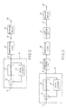
- the coding device 10 receives a coder input signal from a coder input terminal 11 and transmits a coded signal from a coder output terminal 12 for transmission to a decoding device through a transmission line.
- the decoding device and the transmission line will later be described with reference to different ones of the accompanying drawing.
- the coder input signal is, for example, a PCM input signal of 64 kbit/s and will be called a PCM input signal in the following.
- the coded signal is a PCM output signal of 32 kbit/s and will hereafter be referred to as the PCM output signal.
- the coding device 10 encodes the PCM input signal into the PCM output signal.
- Each code of the PCM input signal is eight binary digits, while each code of the PCM output signal is four binary digits.
- the coding device 10 comprises a subtractor 13.
- the subtractor 13 subtracts an estimate of the PCM input signal from the PCM input signal to produce a difference signal.
- a quantizer 14 acts as a coding arrangement for coding the difference signal into the PCM output signal.
- the difference signal is a succession of codes, each assigned to the four binary digits by the quantizer 14.
- a local decoder 15 locally decodes the PCM output signal into a local decoded signal, which is delivered to the subtractor 13 as the estimate of the input signal.
- the local decoder 15 comprises an inverse quantizer 151 for producing a quantized difference signal in response to the PCM output signal.
- An adder 152 adds the local decoded signal to the quantized difference signal to produce a reproduction of the PCM input signal. Both the reproduction and the quantized difference signal are operated upon by a predictor 153 which produces the local decoded signal. In this manner, the local decoder 15 serves as a feedback loop.
- the conventional coding device 10 is operable as a DPCM encoder.
- the coding device 10 is easily modified to an ADPCM encoder when the quantizer 14, the inverse quantizer 151 and the predictor 153 are of the adaptive type known in the art.
- a digital communication system includes the conventional coding device 10 illustrated with reference to Fig. 1 in a transmitting station.
- the coder output terminal 12 is connected to a coder end of the transmission line depicted at 20.
- a decoder end of the transmission line 20 is connected to a decoder input terminal 31 of the decoding device of a receiving station.
- the decoding device is designated by a reference numeral 30.
- the decoding device 30 has a structure which is identical with the local decoder 15 of the coding device 10.
- the decoding device 30 produces a decoded signal in response to the PCM output signal received from the coding device 10 through the transmission line 20.
- the decoded signal is approximately identical with the PCM input signal applied to the coder input terminal 11 of the coding device 10 and is delivered from a decoder output terminal 32 of the decoding device 30 as a decoding output signal.
- another digital communication system includes the conventional coding device 10 illustrated with reference to Fig. 1. Similar parts are designated by like reference numerals.
- the conventional coding device 10 is selectively connected to the transmission line 20.
- the illustrated digital communication system comprises a connection control circuit 21 between the coder output terminal 12 and the coder end of the transmission line 20.
- the connection control circuit 21 the coding device 10 is selectively connected to the transmission line 20 and disconnected therefrom.
- the transmission line 20 is herein said to be put in an on state.
- the transmission line 20 is said to be put in an off state when the coding device 10 is disconnected from the transmission line 20.
- a code insertion circuit 22 Between the decoder end of the transmission line 20 and the decoder input terminal 31, inserted is a code insertion circuit 22.
- the PCM output signal is delivered from the coding device 10 through the transmission line 20 to pass through the code insertion circuit 22.
- the code insertion circuit 22 produces a mute code signal when the transmission line 20 is put in the off state.
- the mute code signal is a specific coded signal into which the quantizer 14 codes the PCM input signal when the input signal carries no information.
- a device which includes the connection control circuit 21 and the code insertion circuit 22 is known as, for example, a DSI (digital speed interpolation) device.
- the DSI device is for use in a time division multiplex system and can transmit an audio signal at a high transmission efficiency.
- a large number of coding devices for example, 200 coding devices are connected to the DSI device (the connection circuit 21) for the transmitting station while 200 decoding devices are connected to the DSI device (the code insertion circuit 22) for the receiving station.
- An audio PCM input signal as herein called, is a digital signal into which the audio signal is coded by PCM.
- Each coding device codes the audio PCM input signal into an audio PCM output signal.
- the DSI device produces the audio PCM output signals of the 200 coding devices to the 200 decoding devices through the transmission line 20 which has a transmission capacity of a predetermined number of channels, for example, 100 channels.
- the DSI device of the transmitting station always checks whether each audio PCM output signal is in an active state or in an inactive state, such as pause.
- the DSI device assigns the channels of the transmission line 20 to the coding devices which produce the audio PCM output signals of the active state.
- the predetermined number of channels is exceeded by the number of the coding devices wherein the audio PCM output signals are in the active state, one or more coding devices in excess of the predetermined number are disconnected from the transmission line 20. This will later be described more in detail.
- Those of the 200 coding devices will be called assigned coding devices which are assigned with the channels.
- the DSI device of the transmitting station transmits an assignment signal.
- the assignment signal indicates correspondence between the assigned coding devices and the channels.
- the transmission line 20 is put in the on state and in the off state with regard to the assigned coding devices and other coding devices, respectively.
- the DSI device of the receiving station distributes the audio PCM output signals received from the assigned coding devices through the channels of the transmission line 20 to the decoding devices which correspond to the assigned coding devices under control of the assignment signal, respectively.
- the DSI device of the receiving station produces mute code signals to the remainder of the decoding devices to which the audio PCM output signals are not distributed.
- one or more coding devices are disconnected from the transmission line 20 and will be called excluded coding devices in the following. Such a state will hereafter be referred to as an exclusion state.
- the excluded coding devices produce the audio PCM output signals of the active state
- the decoding devices corresponding to the excluded coding devices receive the mute code signals.
- signals transmitted through the DSI device are nonpredictive PCM signals, such as the PCM input signals of the coding devices, communication returns to a normal condition as soon as the exclusion state comes to an end.
- signals transmitted through the DSI device are predictive coded signals, such as the PCM output signals of the coding devices, operation of local decoders of the excluded coding devices is different during the exclusion state from operation of those of the decoding devices which correspond to the excluded coding devices. Therefore, communication does not return to the normal condition for a long time, even when the exclusion state comes to an end. As a result, communication of abnormal condition continues.
- the audio PCM output signals are not always identical with the mute code signal because audio PCM input signals of a low level, such as of background noise, are supplied to the coding devices. For this reason, it is impossible to avoid that the decoding operation is subjected to troubles even if the coding devices are again connected to the transmission line 20.
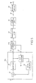
- a coding device 10a is similar to that illustrated with reference to Fig. 1 except that a code converter 16 is inserted between the quantizer 14 and the local decoder 15.
- the code converter 16 serves as a producing arrangement for operative coupling to the transmission line 20 (Fig. 2 or 3) to be responsive to the PCM output signal for producing a first local output signal of a predetermined code and a second local output signal identical with the PCM output signal when the transmission line is put in the off state and the on state, respectively.
- the code converter 16 comprises a mute code producing circuit 161 for producing the mute code signal of the predetermined code as the first local output signal when the transmission line is put in the off state.
- the coding device 10a further receives a control signal from a control input terminal 17, which will later be described.
- the control signal indicates binary "1” and “0” when the transmission line is put in the off state and the on state, respectively.
- a switch circuit 162 selects the first local output signal (the mute code signal) and the second local output signal (the PCM output signal) as a selected one when the control signal indicates binary "1" and "0", respectively.
- the local decoder 15 locally decodes an internal code signal instead of the PCM output signal.
- the selected local output signal is supplied to the local decoder 15 via a line 18 as the internal code signal.
- a digital communication system includes the coding device 10a in the transmitting station and is similar to that illustrated with reference to Fig. 3 except that the connection control circuit is improved in Fig. 5 into an improved connection control circuit 21a for producing the control signal as will later become clear.
- connection control circuit 21a produces the control signal indicative of the binary "0" and "1" when the coding device 10a is selectively connected to the transmission line 20 and disconnected therefrom, respectively.
- the control signal is supplied to the control input terminal 17 of the coding device 10a.
- connection control circuit 21a produces the control signal indicative of binary "1" so that the code converter 16 may deliver the mute code signal to the local decoder 15.
- the code insertion circuit 22 of the receiving station receives an information signal which indicates that the coding device 10a is disconnected from the transmission line 20.
- the information signal is, for example, the assignment signal.
- the code insertion circuit 22 supplies the mute code signal to the decoding device 30 in response to the information signal.
- the decoding device 30 always receives a signal identical with a signal used in the local decoder 15 of the coding device 10a no matter however the connection control circuit 21a may operate or not. This is because both the code converter 16 produces the mute code signal identical with the mute code signal of the code insertion circuit 22 when the coding device 10a is disconnected from the transmission line 20. Thereby, operation of the local decoder 15 of the coding device 10a always coincide with operation of the decoding device 30.
Landscapes
- Engineering & Computer Science (AREA)
- Theoretical Computer Science (AREA)
- Compression, Expansion, Code Conversion, And Decoders (AREA)
- Transmission Systems Not Characterized By The Medium Used For Transmission (AREA)
- Time-Division Multiplex Systems (AREA)
Applications Claiming Priority (2)
| Application Number | Priority Date | Filing Date | Title |
|---|---|---|---|
| JP219995/85 | 1985-10-04 | ||
| JP60219995A JPH0752845B2 (ja) | 1985-10-04 | 1985-10-04 | 差分符号化回路 |
Publications (3)
| Publication Number | Publication Date |
|---|---|
| EP0217412A2 true EP0217412A2 (de) | 1987-04-08 |
| EP0217412A3 EP0217412A3 (en) | 1989-04-26 |
| EP0217412B1 EP0217412B1 (de) | 1991-09-25 |
Family
ID=16744277
Family Applications (1)
| Application Number | Title | Priority Date | Filing Date |
|---|---|---|---|
| EP86113694A Expired EP0217412B1 (de) | 1985-10-04 | 1986-10-03 | Wahlweise mit einer Übertragungsleitung verbundene Kodierungsvorrichtung |
Country Status (5)
| Country | Link |
|---|---|
| US (1) | US4807250A (de) |
| EP (1) | EP0217412B1 (de) |
| JP (1) | JPH0752845B2 (de) |
| CA (1) | CA1258532A (de) |
| DE (1) | DE3681674D1 (de) |
Cited By (1)
| Publication number | Priority date | Publication date | Assignee | Title |
|---|---|---|---|---|
| GB2319440A (en) * | 1996-11-05 | 1998-05-20 | Samsung Electronics Co Ltd | Digital signal processing with reduced power consumption |
Families Citing this family (18)
| Publication number | Priority date | Publication date | Assignee | Title |
|---|---|---|---|---|
| US4965580A (en) * | 1988-09-26 | 1990-10-23 | Mitsubishi Denki Kabushiki Kaisha | Quantizer and inverse-quantizer |
| JPH07109991B2 (ja) * | 1989-06-05 | 1995-11-22 | 日本ビクター株式会社 | ノイズシェーピング型再量子化回路 |
| JP2754741B2 (ja) * | 1989-06-09 | 1998-05-20 | キヤノン株式会社 | 符号化装置 |
| CA2063879C (en) * | 1991-05-28 | 1998-05-05 | Albert D. Edgar | Positive feedback error diffusion signal processing |
| KR930009436B1 (ko) * | 1991-12-27 | 1993-10-04 | 삼성전자 주식회사 | 파형부호화/복호화 장치 및 방법 |
| US5453986A (en) * | 1993-01-08 | 1995-09-26 | Multi-Tech Systems, Inc. | Dual port interface for a computer-based multifunction personal communication system |
| US5617423A (en) * | 1993-01-08 | 1997-04-01 | Multi-Tech Systems, Inc. | Voice over data modem with selectable voice compression |
| US5546395A (en) * | 1993-01-08 | 1996-08-13 | Multi-Tech Systems, Inc. | Dynamic selection of compression rate for a voice compression algorithm in a voice over data modem |
| US6009082A (en) * | 1993-01-08 | 1999-12-28 | Multi-Tech Systems, Inc. | Computer-based multifunction personal communication system with caller ID |
| US5754589A (en) * | 1993-01-08 | 1998-05-19 | Multi-Tech Systems, Inc. | Noncompressed voice and data communication over modem for a computer-based multifunction personal communications system |
| US5535204A (en) * | 1993-01-08 | 1996-07-09 | Multi-Tech Systems, Inc. | Ringdown and ringback signalling for a computer-based multifunction personal communications system |
| US7082106B2 (en) | 1993-01-08 | 2006-07-25 | Multi-Tech Systems, Inc. | Computer-based multi-media communications system and method |
| US5864560A (en) * | 1993-01-08 | 1999-01-26 | Multi-Tech Systems, Inc. | Method and apparatus for mode switching in a voice over data computer-based personal communications system |
| US5812534A (en) * | 1993-01-08 | 1998-09-22 | Multi-Tech Systems, Inc. | Voice over data conferencing for a computer-based personal communications system |
| US5452289A (en) * | 1993-01-08 | 1995-09-19 | Multi-Tech Systems, Inc. | Computer-based multifunction personal communications system |
| US5757801A (en) * | 1994-04-19 | 1998-05-26 | Multi-Tech Systems, Inc. | Advanced priority statistical multiplexer |
| US5682386A (en) * | 1994-04-19 | 1997-10-28 | Multi-Tech Systems, Inc. | Data/voice/fax compression multiplexer |
| JPH10243402A (ja) * | 1997-02-27 | 1998-09-11 | Toshiba Corp | 画像処理装置及び画像処理方法 |
Family Cites Families (11)
| Publication number | Priority date | Publication date | Assignee | Title |
|---|---|---|---|---|
| US2669608A (en) * | 1950-10-27 | 1954-02-16 | Bell Telephone Labor Inc | Noise reduction in quantized pulse transmission systems with large quanta |
| NL277910A (de) * | 1961-05-02 | |||
| US3516022A (en) * | 1966-11-17 | 1970-06-02 | Bell Telephone Labor Inc | Delta modulation encoders with randomized idle circuit noise |
| FR2077475B1 (de) * | 1969-12-31 | 1976-07-23 | Radiotechnique Compelec | |
| JPS5143936B2 (de) * | 1971-12-28 | 1976-11-25 | ||
| JPS5333386B2 (de) * | 1974-01-22 | 1978-09-13 | ||
| JPS6036153B2 (ja) * | 1976-10-22 | 1985-08-19 | 日本電気株式会社 | 予測符号化装置 |
| JPS6016777B2 (ja) * | 1976-12-25 | 1985-04-27 | 株式会社東芝 | 信号伝送方式 |
| US4167653A (en) * | 1977-04-15 | 1979-09-11 | Nippon Electric Company, Ltd. | Adaptive speech signal detector |
| US4554670A (en) * | 1982-04-14 | 1985-11-19 | Nec Corporation | System and method for ADPCM transmission of speech or like signals |
| FR2538645B1 (fr) * | 1982-12-28 | 1986-04-11 | Thomson Csf | Procede et dispositif d'interpolation de la parole dans un systeme de transmission de parole numerisee |
-
1985
- 1985-10-04 JP JP60219995A patent/JPH0752845B2/ja not_active Expired - Lifetime
-
1986
- 1986-10-03 EP EP86113694A patent/EP0217412B1/de not_active Expired
- 1986-10-03 CA CA000519680A patent/CA1258532A/en not_active Expired
- 1986-10-03 DE DE8686113694T patent/DE3681674D1/de not_active Expired - Lifetime
- 1986-10-06 US US06/915,351 patent/US4807250A/en not_active Expired - Fee Related
Cited By (3)
| Publication number | Priority date | Publication date | Assignee | Title |
|---|---|---|---|---|
| GB2319440A (en) * | 1996-11-05 | 1998-05-20 | Samsung Electronics Co Ltd | Digital signal processing with reduced power consumption |
| US6141761A (en) * | 1996-11-05 | 2000-10-31 | Samsung Electronics Co., Ltd. | Low power consuming operating device for digital signal processing using a probability distribution of input digital signals and predetermined output signals |
| GB2319440B (en) * | 1996-11-05 | 2001-06-06 | Samsung Electronics Co Ltd | Low power consuming operating device for digital signal processing |
Also Published As
| Publication number | Publication date |
|---|---|
| JPS6281125A (ja) | 1987-04-14 |
| DE3681674D1 (de) | 1991-10-31 |
| CA1258532A (en) | 1989-08-15 |
| EP0217412A3 (en) | 1989-04-26 |
| EP0217412B1 (de) | 1991-09-25 |
| JPH0752845B2 (ja) | 1995-06-05 |
| US4807250A (en) | 1989-02-21 |
Similar Documents
| Publication | Publication Date | Title |
|---|---|---|
| EP0217412B1 (de) | Wahlweise mit einer Übertragungsleitung verbundene Kodierungsvorrichtung | |
| US5142568A (en) | Data communication apparatus which can use either an analog or a digital line | |
| US4377860A (en) | Bandwidth reduction method and structure for combining voice and data in a PCM channel | |
| US4734768A (en) | Method for transmitting differential pulse code modulation (DPCM) values | |
| US4630257A (en) | Duplex speech transmission method and a system therefor | |
| EP0279799B1 (de) | Verfahren und Vorrichtung zur variablen Längenkodierung | |
| US6393000B1 (en) | Communication method and apparatus with transmission of a second signal during absence of a first one | |
| CA2108338A1 (en) | Adaptive Video Encoder for Two-Layer Encoding of Video Signals on ATM (Asynchronous Transfer Mode) Networks | |
| JP3252782B2 (ja) | モデム信号対応音声符号化復号化装置 | |
| EP0149536A2 (de) | Übertragungssystem | |
| KR890005232B1 (ko) | 디지탈 스위칭 모듈 | |
| US6256298B1 (en) | Mobile telecommunication system | |
| US6882969B2 (en) | Variable bit rate digital circuit multiplication equipment with tandem passthrough function | |
| US3975686A (en) | Loss signal generation for delta-modulated signals | |
| US4677492A (en) | Method for the intermediate storage of facsimile data of groups 2 and 3 | |
| US5140612A (en) | Modem for use in a data communication system | |
| JPS62123843A (ja) | 通信方式 | |
| JP2691189B2 (ja) | 符号復号器 | |
| JPS6314544B2 (de) | ||
| EP0810762A3 (de) | Telefongerät mit einer Aufzeichnungsfunktion | |
| JP2584447B2 (ja) | 時分割多重化装置 | |
| KR100429544B1 (ko) | 이산신호 송/수신기능을 갖는 이동통신 단말기 | |
| JP2908335B2 (ja) | 情報処理装置の音声・ディジタルデータ多重伝送方式 | |
| JPS63141423A (ja) | 符号化復号化装置 | |
| CA1200331A (en) | Adpcm encoder/decoder with signalling bit insertion |
Legal Events
| Date | Code | Title | Description |
|---|---|---|---|
| PUAI | Public reference made under article 153(3) epc to a published international application that has entered the european phase |
Free format text: ORIGINAL CODE: 0009012 |
|
| 17P | Request for examination filed |
Effective date: 19861003 |
|
| AK | Designated contracting states |
Kind code of ref document: A2 Designated state(s): DE FR GB |
|
| PUAL | Search report despatched |
Free format text: ORIGINAL CODE: 0009013 |
|
| AK | Designated contracting states |
Kind code of ref document: A3 Designated state(s): DE FR GB |
|
| 17Q | First examination report despatched |
Effective date: 19900523 |
|
| GRAA | (expected) grant |
Free format text: ORIGINAL CODE: 0009210 |
|
| AK | Designated contracting states |
Kind code of ref document: B1 Designated state(s): DE FR GB |
|
| PGFP | Annual fee paid to national office [announced via postgrant information from national office to epo] |
Ref country code: GB Payment date: 19911001 Year of fee payment: 6 |
|
| PGFP | Annual fee paid to national office [announced via postgrant information from national office to epo] |
Ref country code: FR Payment date: 19911029 Year of fee payment: 6 |
|
| ET | Fr: translation filed | ||
| REF | Corresponds to: |
Ref document number: 3681674 Country of ref document: DE Date of ref document: 19911031 |
|
| PGFP | Annual fee paid to national office [announced via postgrant information from national office to epo] |
Ref country code: DE Payment date: 19911230 Year of fee payment: 6 |
|
| PLBE | No opposition filed within time limit |
Free format text: ORIGINAL CODE: 0009261 |
|
| STAA | Information on the status of an ep patent application or granted ep patent |
Free format text: STATUS: NO OPPOSITION FILED WITHIN TIME LIMIT |
|
| 26N | No opposition filed | ||
| PG25 | Lapsed in a contracting state [announced via postgrant information from national office to epo] |
Ref country code: GB Effective date: 19921003 |
|
| GBPC | Gb: european patent ceased through non-payment of renewal fee |
Effective date: 19921003 |
|
| PG25 | Lapsed in a contracting state [announced via postgrant information from national office to epo] |
Ref country code: FR Effective date: 19930630 |
|
| PG25 | Lapsed in a contracting state [announced via postgrant information from national office to epo] |
Ref country code: DE Effective date: 19930701 |
|
| REG | Reference to a national code |
Ref country code: FR Ref legal event code: ST |