EP0217464A2 - Procédé pour la détermination de l'atténuation photonique dans un domaine d'un corps et dispositif pour la mise en oeuvre du procédé - Google Patents
Procédé pour la détermination de l'atténuation photonique dans un domaine d'un corps et dispositif pour la mise en oeuvre du procédé Download PDFInfo
- Publication number
- EP0217464A2 EP0217464A2 EP86201647A EP86201647A EP0217464A2 EP 0217464 A2 EP0217464 A2 EP 0217464A2 EP 86201647 A EP86201647 A EP 86201647A EP 86201647 A EP86201647 A EP 86201647A EP 0217464 A2 EP0217464 A2 EP 0217464A2
- Authority
- EP
- European Patent Office
- Prior art keywords
- arrangement
- primary beam
- detector
- scattered radiation
- photo
- Prior art date
- Legal status (The legal status is an assumption and is not a legal conclusion. Google has not performed a legal analysis and makes no representation as to the accuracy of the status listed.)
- Granted
Links
- UAEPNZWRGJTJPN-UHFFFAOYSA-N CC1CCCCC1 Chemical compound CC1CCCCC1 UAEPNZWRGJTJPN-UHFFFAOYSA-N 0.000 description 1
Images
Classifications
-
- G—PHYSICS
- G01—MEASURING; TESTING
- G01N—INVESTIGATING OR ANALYSING MATERIALS BY DETERMINING THEIR CHEMICAL OR PHYSICAL PROPERTIES
- G01N23/00—Investigating or analysing materials by the use of wave or particle radiation, e.g. X-rays or neutrons, not covered by groups G01N3/00 – G01N17/00, G01N21/00 or G01N22/00
- G01N23/02—Investigating or analysing materials by the use of wave or particle radiation, e.g. X-rays or neutrons, not covered by groups G01N3/00 – G01N17/00, G01N21/00 or G01N22/00 by transmitting the radiation through the material
- G01N23/06—Investigating or analysing materials by the use of wave or particle radiation, e.g. X-rays or neutrons, not covered by groups G01N3/00 – G01N17/00, G01N21/00 or G01N22/00 by transmitting the radiation through the material and measuring the absorption
Definitions
- the invention relates to a method for determining the photo-weakening in an area of an examination body penetrated by a primary beam, the scattered radiation generated in the primary beam area being measured and the photo-weakening being determined from the measured values, and an arrangement for carrying out the method.
- Such a method which can basically be used in medical diagnostics or in material testing (including food testing), is known from J. Phys. E: Sci. Instrum., Vol. 18, 1985, pages 354 to 357.
- the "Ratio" method referred method of the test article is irradiated by a primary beam and that generated in the region of interest of the primary beam in the examination body and at an angle of 90 0 emerging scattered radiation is measured, namely true beam portion separated by Compton component and elastic S.
- the photo-weakening in the mentioned region of the primary beam can be concluded from the ratio of the elastic scattered radiation component to the Compton component.
- the separate detection of Compoton scattered radiation and elastic scattered radiation takes advantage of the fact that the energy of an X-ray quantum decreases in a Compton scattering process, while in the case of elastic scattering (so-called Rayleigh scattering) the scattered X-ray quantum does not experience any change in energy.
- the amplitude of the X-ray quanta upon arrival must be generated pulses, which is proportional to the energy of the X-ray quantum, determined and evaluated by means of a pulse height analyzer, and for this to be possible at all, monochromatic X-ray radiation must be used.
- radiation sources for monochromatic X-rays are much less intense than radiation sources for polychromatic X-rays.
- the intensity of the elastically scattered radiation is very low because elastically scattered radiation is concentric in the forward direction if the beam energy is sufficiently high (60 keV) to penetrate typical objects.
- extremely long measuring times are required in order to achieve sufficiently precise results.
- this object is achieved in that the stray radiation from two non-identical sections of the primary beam is measured in two different spectral ranges with two detector arrangements and that the photo-absorption according to the relationship is obtained from the measured values obtained in the process is determined, where a1, a2, b1, b2 are constants and Q1 is the quotient of the measured values of the first detector arrangement for the first and the second spectral range and Q2 is the quotient of the measured values of the second detector arrangement for the first and the second spectral range.
- the intensity of the scattered radiation detected by one of the two detector arrangements depends not only on the electron density and the scattering cross section in the section of the primary beam whose scattered radiation is detected by the detector arrangement in question, but also on the attenuation which the X-rays emit on their way from entering the body up to the relevant section and from this (as scattered radiation) to the detector arrangement.
- This weakening of the X-rays is caused on the one hand by their scattering and on the other hand by their absorption, i.e. the attenuation of the radiation consists of a scatter component and an absorption component.
- the scatter component is essentially independent of the energy of the X-ray radiation or of the spectral range, while the absorption component, which is caused by photo-absorption, depends strongly on the energy (it is inversely proportional to the third power of the energy).
- the scatter component of the attenuation is the same in the two measured values of a detector arrangement that result in the different spectral ranges. Because of this and because of the exponential relationship between the intensity of the scattered radiation and the attenuation, the scattered portion is eliminated when the logarithm of the two measured values is formed. This therefore essentially only depends on the photo absorption along the path that the primary radiation or the scattered beam has traveled through the body.
- the arrangement for carrying out the method is characterized by an X-ray tube for generating an X-ray beam, a first diaphragm arrangement for blanking out a primary beam, two detector arrangements which detect the scattered radiation from two sections of the primary beam by means of a second diaphragm arrangement and which are arranged so that they are almost the same paths can be achieved by the X-ray radiation, and by a computing device for determining the photo-weakening from the measured values.
- the energy spectrum of the X-ray tube itself is changed between the two measurements. But it is also possible to use this energy spectrum to leave unchanged and to arrange a switchable filter in front of the examination area, which hardens the X-rays in the two switchover positions of the filter in different ways, so that two different energy spectra arise. In this case, however, both spectral ranges have the same upper limit energy, which is defined by the tube voltage. The spectra therefore do not differ from each other as much as in the aforementioned training.
- each detector arrangement contains a detector which converts the scattered radiation in two different spectral ranges into one electrical signal each.
- the energy spectrum in the primary beam is left completely unchanged, but the detector - a so-called split detector - delivers two electrical signals that correspond to the intensity of the scattered radiation in two different spectral ranges.
- the advantage is that only one measurement has to be carried out, but the disadvantage is that for each of the two signals that a detector arrangement supplies, a processing channel must be present (preamplifier, etc.).
- the invention does not require the use of a monochromatic radiation source to generate the primary beam. Therefore, an X-ray tube can be used which provides a bremsradiation spectrum with very high intensity, which results in short measuring times. A shortening of the measuring time also results from the fact that the energy of the X-ray quanta does not have to be measured and that the elastically scattered radiation does not have to be recorded separately.
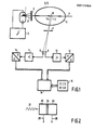
- Fig. 1 denotes an X-ray tube, which is connected to a high-voltage generator 2, which can be switched to two different high voltages, for example 100 kV and 160 kV.
- a thin primary beam 5 (pencil beam) is generated from the X-ray beam 3 emitted by the X-ray tube, ie a beam that has only a small extent perpendicular to its direction of propagation (for example 2 mm ⁇ 2 mm).
- the primary beam passes through an examination body 6 and generates scattered radiation in it.
- Each of the two detectors 8 and 9 "sees" a certain comparatively short, approximately punctiform section of the primary beam through the opening in the diaphragm, ie it detects the section of the primary beam generated in this section and in the direction of the connecting lines L1 and L2 with the detectors 8 or 9 scattered radiation.
- the output signals of the detectors 8 and 9 are fed via a preamplifier 10 and 11 and a digital-to-analog converter 12 and 13 to a computing device 14.
- a first measurement is carried out at a tube voltage of 100 kV and a second measurement at a tube voltage of 160 kV.
- the two measured values, which each of the detectors 8 and 9 provides, are processed in the computing device 14 using the constants c1, c2, b1, b2 stored in a memory 15. This processing is based on the following considerations.
- the attenuation which the X-ray radiation experiences on its way through the examination body to one of the detectors depends exponentially on the integral of the attenuation coefficient along the path covered. Accordingly, the relationship applies to the signal S11 that the detector 8 generates in the first spectral range E1
- c11 is a proportionality constant which takes into account such factors as measurement time and detector sensitivity and u (x, E1) the attenuation coefficient dependent on location x and energy E1.
- the attenuation coefficient u can be broken down into an absorption coefficient and a scattering coefficient, which in turn can be split into an energy-dependent term and an only location-dependent term, so that the relationship applies
- a e (x) is a coefficient that depends only on location x or only on the scatter density at this location, while f c (E) is a factor that describes the energy dependence of the scatter.
- ap (x) denotes the energy-independent photo absorption coefficient, which only depends on the location, and fp ( E ) describes the energy dependence of the photo absorption. If the two voltages at which the X-ray source 1 is operated lie between ..80 kV and ..50 kV, the scatter is practically not dependent on the energy, ie f c (E) is a constant. On the other hand, photo weakening depends heavily on energy; it is known that it is inversely proportional to the third power of energy. If one takes into account that f c (E) is practically a constant, then by inserting equation (5) into equation (4)
- Ap (L1) represents the photo absorption along path L1.
- the constants d1 and b1 can be determined in the following way:
- the examination body 6 is replaced by a homogeneous calibration body with a defined geometry and known photo absorption coefficient ap, so that the photo absorption can be calculated on the basis of the predetermined path L1, which the scattered radiation takes through this calibration body. Then the signals S11 and S12 are measured at two different x-ray tube voltages and the quotient Q1 is formed therefrom. The measurement process described is then repeated with a second likewise homogeneous calibration body with the same geometry, but with a substantially different, also known photo absorption. If the values found in the two measurements with each of the two calibration bodies or the calculated values are inserted into equation (7), two equations are obtained for determining the unknowns d1, b1.
- the measurement process described is preferably repeated with further calibration bodies in order to reduce the influence of measurement inaccuracies, etc.
- the values d1, b1 found in this way depend only on the spectral distribution of the energy in the primary beam, i.e. on the voltage at the X-ray tube and on the geometry of the measuring arrangement. If the subsequent measurements for determining the photo-weakening are therefore carried out at the same tube voltages or at the same position of the detectors 8 and 9 and the diaphragm 7 with respect to the primary beam 5, these values do not change.
- the photo weakening according to equation (8) can be carried out on path L2 assigned to this detector.
- Q2 is the quotient of the measured values measured by this detector at energies E1 and E2 and d2 and b2 are constants which, however, are not necessarily identical to d1 and b1. Differences in b1 and b2 result from possible differences in the sensitivities of the detectors, d1 and d2 depend on the brake beam spectral distribution at E1 and E2 and are not exactly identical due to the fact that the change in the energy caused by the Compton scattering process X-ray quanta leads to slightly different photo attenuation in detectors 1 and 2.
- the detectors 8 and 9 and the sections on the primary beam whose scattered radiation they detect are close to one another, the paths which the scattered radiation travels from the primary beam 5 through the examination body 6 to the detectors 8 and 9 are very closely adjacent to one another. For this reason, the scattered rays experience practically the same photo absorption.
- the photo absorption which the X-ray radiation travels on the way to the first section on the primary beam detected by the detector 8 is also the same for both paths L1 and L2.
- the two paths L1 and L2 differ only by the distance 16 which the primary beam 5 must travel in order to get from the section on the primary beam detected by the detector 8 to the section detected by the detector 9.
- the calculation of the photo weakening Ap in the area 16 takes place in the computing device 14 on the basis of the measured values from which the quotients Q1 and Q2 are formed, and from the constants stored in the memory 15 in accordance with equation (9).
- This detector arrangement consists of two sections 22 and 23, which are arranged one behind the other as seen in the direction of the scattered radiation 21 to be detected.
- the two sections 22 and 23 are expediently separated by a layer 24 hardening the X-radiation.
- the section 22 hit first by stray radiation is designed such that it essentially only converts the longer-wave part of the stray radiation spectrum into an electrical signal which appears at the detector output 25.
- the remaining part, possibly hardened by layer 24 of the scattered radiation spectrum is converted into an electrical signal by section 23 at output 26.
- the so-called split detector shown is able to deliver signals corresponding to the intensity of the scattered radiation in two different spectral ranges.
- the advantage that only one measurement is required when using such detectors is offset by the disadvantage that instead of two channels (10, 12 or 11, 13) four are required to process the measured values.
Landscapes
- Physics & Mathematics (AREA)
- Health & Medical Sciences (AREA)
- Life Sciences & Earth Sciences (AREA)
- Chemical & Material Sciences (AREA)
- Analytical Chemistry (AREA)
- Biochemistry (AREA)
- General Health & Medical Sciences (AREA)
- General Physics & Mathematics (AREA)
- Immunology (AREA)
- Pathology (AREA)
- Analysing Materials By The Use Of Radiation (AREA)
- Apparatus For Radiation Diagnosis (AREA)
Applications Claiming Priority (2)
| Application Number | Priority Date | Filing Date | Title |
|---|---|---|---|
| DE3534702 | 1985-09-28 | ||
| DE19853534702 DE3534702A1 (de) | 1985-09-28 | 1985-09-28 | Verfahren zur bestimmung der fotoschwaechung in einem bereich eines untersuchungskoerpers und anordnung zur durchfuehrung des verfahrens |
Publications (3)
| Publication Number | Publication Date |
|---|---|
| EP0217464A2 true EP0217464A2 (fr) | 1987-04-08 |
| EP0217464A3 EP0217464A3 (en) | 1989-03-15 |
| EP0217464B1 EP0217464B1 (fr) | 1991-12-18 |
Family
ID=6282246
Family Applications (1)
| Application Number | Title | Priority Date | Filing Date |
|---|---|---|---|
| EP86201647A Expired - Lifetime EP0217464B1 (fr) | 1985-09-28 | 1986-09-23 | Procédé pour la détermination de l'atténuation photonique dans un domaine d'un corps et dispositif pour la mise en oeuvre du procédé |
Country Status (4)
| Country | Link |
|---|---|
| US (1) | US4785401A (fr) |
| EP (1) | EP0217464B1 (fr) |
| JP (1) | JPS6280541A (fr) |
| DE (2) | DE3534702A1 (fr) |
Families Citing this family (12)
| Publication number | Priority date | Publication date | Assignee | Title |
|---|---|---|---|---|
| DE4034602A1 (de) * | 1990-06-20 | 1992-05-07 | Philips Patentverwaltung | Anordnung zur messung des impulsuebertragsspektrums von roentgenquanten |
| JP3408848B2 (ja) * | 1993-11-02 | 2003-05-19 | 株式会社日立メディコ | 散乱x線補正法及びx線ct装置並びに多チャンネルx線検出器 |
| CA2348150C (fr) | 2000-05-25 | 2007-03-13 | Esam M.A. Hussein | Systeme non rotatif a rayons x pour l'imagerie tridimensionnelle et triparametrique |
| CN1946342A (zh) * | 2004-04-21 | 2007-04-11 | 皇家飞利浦电子股份有限公司 | 锥束相干散射计算机断层摄影装置 |
| CA2513990C (fr) * | 2004-08-27 | 2010-09-14 | Paul Jacob Arsenault | Reconstitution d'image a diffusion par rayons x, par equilibrage des ecarts entre les reponses de detecteurs, et dispositif connexe |
| US20080219404A1 (en) * | 2007-03-08 | 2008-09-11 | Bio-Imaging Research, Inc. | Method and Apparatus to Facilitate Formation of a Two-Dimensional Image Using X-Ray Fan Beam Scatter |
| US20080253525A1 (en) * | 2007-04-11 | 2008-10-16 | Boyden Edward S | Compton scattered x-ray visualizing, imaging, or information providing of at least some dissimilar matter |
| US8041006B2 (en) * | 2007-04-11 | 2011-10-18 | The Invention Science Fund I Llc | Aspects of compton scattered X-ray visualization, imaging, or information providing |
| US20080253522A1 (en) * | 2007-04-11 | 2008-10-16 | Searete Llc, A Limited Liability Corporation Of The State Of Delaware | Tool associated with compton scattered X-ray visualization, imaging, or information provider |
| US20080253527A1 (en) * | 2007-04-11 | 2008-10-16 | Searete Llc, A Limited Liability Corporation Of The State Of Delaware | Limiting compton scattered x-ray visualizing, imaging, or information providing at particular regions |
| US7627085B2 (en) * | 2007-04-11 | 2009-12-01 | Searete Llc | Compton scattered X-ray depth visualization, imaging, or information provider |
| US8837677B2 (en) * | 2007-04-11 | 2014-09-16 | The Invention Science Fund I Llc | Method and system for compton scattered X-ray depth visualization, imaging, or information provider |
Family Cites Families (9)
| Publication number | Priority date | Publication date | Assignee | Title |
|---|---|---|---|---|
| US3769507A (en) * | 1971-08-25 | 1973-10-30 | Research Corp | Dynamic radiography |
| US3843881A (en) * | 1973-01-11 | 1974-10-22 | Phillips Petroleum Co | Detection of elements by irradiating material and measuring scattered radiation at two energy levels |
| DK131955C (da) * | 1973-10-09 | 1976-02-23 | I Leunbach | Fremgangsmade og anleg til bestemmelse af elektrontetheden i et delvolumen af et legeme |
| DE2544354A1 (de) * | 1975-10-03 | 1977-04-14 | Siemens Ag | Verfahren zur bestimmung der dichte von koerpern mittels durchdingender strahlen und geraet zu seiner durchfuehrung |
| DE2655230A1 (de) * | 1976-12-06 | 1978-06-15 | Siemens Ag | Verfahren und einrichtung zur roentgen- und gammastreustrahlen-tomographie |
| DE2920051C2 (de) * | 1979-05-18 | 1984-04-19 | Philips Patentverwaltung Gmbh, 2000 Hamburg | Röntgengerät zur Ermittlung der Absorptionsverteilung in einem ebenen Untersuchungsbereich |
| DE2944147A1 (de) * | 1979-11-02 | 1981-05-14 | Philips Patentverwaltung Gmbh, 2000 Hamburg | Anordnung zur ermittlung der streudichteverteilung in einem ebenen untersuchungsbereich |
| DE3035524A1 (de) * | 1980-09-19 | 1982-05-06 | Philips Patentverwaltung Gmbh, 2000 Hamburg | Streustrahlen-durchleuchtungsanordnung |
| JPS5770432A (en) * | 1980-10-20 | 1982-04-30 | Deiemuetsukusu Asoshieetsusu | Radiation scanning method and apparatus |
-
1985
- 1985-09-28 DE DE19853534702 patent/DE3534702A1/de not_active Withdrawn
-
1986
- 1986-09-22 US US06/909,807 patent/US4785401A/en not_active Expired - Fee Related
- 1986-09-23 EP EP86201647A patent/EP0217464B1/fr not_active Expired - Lifetime
- 1986-09-23 DE DE8686201647T patent/DE3682999D1/de not_active Expired - Lifetime
- 1986-09-26 JP JP61227906A patent/JPS6280541A/ja active Pending
Also Published As
| Publication number | Publication date |
|---|---|
| DE3534702A1 (de) | 1987-04-09 |
| DE3682999D1 (de) | 1992-01-30 |
| US4785401A (en) | 1988-11-15 |
| EP0217464B1 (fr) | 1991-12-18 |
| EP0217464A3 (en) | 1989-03-15 |
| JPS6280541A (ja) | 1987-04-14 |
Similar Documents
| Publication | Publication Date | Title |
|---|---|---|
| EP0571017B1 (fr) | Procédé de filtrage pour un système rayons X et agencement pour réaliser ledit procédé de filtrage | |
| EP0209952B1 (fr) | Procédé pour la mesure de la répartition spatiale de rayonnement X diffusé élastiquement ainsi que le dispositif pour la mise en oeuvre du procédé | |
| DE2421649A1 (de) | Vorrichtung zur pruefung einer probe oder eines materials durch messung der absorption der gamma- oder roentgenstrahlung | |
| DE2648434A1 (de) | Verfahren zum analysieren von kohle oder koks | |
| EP0496454A1 (fr) | Appareil de radiographie | |
| EP0217464B1 (fr) | Procédé pour la détermination de l'atténuation photonique dans un domaine d'un corps et dispositif pour la mise en oeuvre du procédé | |
| DE3300406A1 (de) | Referenzdetektorvorrichtung fuer multidetektor-tomodensitometer und mit dieser vorrichtung ausgeruestetes tomodensitometer | |
| DE2543011A1 (de) | Einrichtung zur roentgenstrahlen- fluoreszenzanalyse | |
| DE1955195B2 (de) | Einrichtung zum Messen der Energie von in Beschleunigern für die Strahlentherapie beschleunigten elektrisch geladenen Teilchen mittels Cerenkov-Strahlung | |
| DE2411841C3 (de) | Auger-Elektronenspektrometer | |
| DE3003909C2 (de) | Verfahren zur gleichzeitigen Messung von a- und ß-Teilchen und Detektoreinrichtung zur Durchführung des Verfahrens | |
| DE1598120B2 (de) | Vorrichtung zur bestimmung des flaechenanteils verschiedener phasen auf oberflaechen heterogen aufgebauter metallischer oder nichtmetallischer stoffe | |
| DE1598841A1 (de) | Einrichtung zum Analysieren und/oder Trennen von Gemischen | |
| DE1798241A1 (de) | Verfahren und Vorrichtung zur Bestimmung der mittleren Groesse von Feststoffteilchen in einem Fluidum | |
| EP2217946B1 (fr) | Dispositif pour la détermination en ligne du contenu d'une substance et procédé utilisant un tel dispositif | |
| DE2413136A1 (de) | Verfahren und vorrichtung zur bestimmung der masse und des schwerpunkts eines gegenstands | |
| DE3136819A1 (de) | Roentgenstrahlenfluoreszenzverfahren zum bestimmen der mittleren durchschnittskonzentration eines elements in einer probe | |
| DE2440120A1 (de) | Vorrichtung zur wiedergabe der energieverteilung eines aus geladenen teilchen bestehenden strahles | |
| DE19603000A1 (de) | Verfahren zum Kalibrieren einer Anordnung zur Ermittlung des Impulsübertragsspektrums und Kalibriereinheit zur Durchführung des Verfahrens | |
| DE3300566C2 (fr) | ||
| DE2001513A1 (de) | Vorrichtung zur Messung des Gehalts einer Probe an einem Element durch Gamma-Absorptiometrie | |
| DE1960508A1 (de) | Radioisotopen-Roentgenfluoreszenzanalysator zur Elementaranalyse von Gesteinen und Erzen unter natuerlichen Lagerungsbedingungen | |
| DE1201089B (de) | Verfahren und Vorrichtung zur quantitativen Roentgenstrahlen-Fluoreszenzanalyse | |
| DE3135838C2 (de) | Verfahren zur Füllstandsmessung von mit Pulvern oder Flüssigkeiten gefüllten Rohren oder Hülsen | |
| DE2364081C3 (de) | Verfahren und Vorrichtung zum Klassifizieren von Reifen |
Legal Events
| Date | Code | Title | Description |
|---|---|---|---|
| PUAI | Public reference made under article 153(3) epc to a published international application that has entered the european phase |
Free format text: ORIGINAL CODE: 0009012 |
|
| AK | Designated contracting states |
Kind code of ref document: A2 Designated state(s): DE FR GB |
|
| RAP1 | Party data changed (applicant data changed or rights of an application transferred) |
Owner name: N.V. PHILIPS' GLOEILAMPENFABRIEKEN Owner name: PHILIPS PATENTVERWALTUNG GMBH |
|
| PUAL | Search report despatched |
Free format text: ORIGINAL CODE: 0009013 |
|
| AK | Designated contracting states |
Kind code of ref document: A3 Designated state(s): DE FR GB |
|
| 17P | Request for examination filed |
Effective date: 19890905 |
|
| 17Q | First examination report despatched |
Effective date: 19910226 |
|
| GRAA | (expected) grant |
Free format text: ORIGINAL CODE: 0009210 |
|
| AK | Designated contracting states |
Kind code of ref document: B1 Designated state(s): DE FR GB |
|
| REF | Corresponds to: |
Ref document number: 3682999 Country of ref document: DE Date of ref document: 19920130 |
|
| GBT | Gb: translation of ep patent filed (gb section 77(6)(a)/1977) | ||
| ET | Fr: translation filed | ||
| PLBE | No opposition filed within time limit |
Free format text: ORIGINAL CODE: 0009261 |
|
| STAA | Information on the status of an ep patent application or granted ep patent |
Free format text: STATUS: NO OPPOSITION FILED WITHIN TIME LIMIT |
|
| 26N | No opposition filed | ||
| PGFP | Annual fee paid to national office [announced via postgrant information from national office to epo] |
Ref country code: GB Payment date: 19940901 Year of fee payment: 9 |
|
| PGFP | Annual fee paid to national office [announced via postgrant information from national office to epo] |
Ref country code: FR Payment date: 19940928 Year of fee payment: 9 |
|
| PGFP | Annual fee paid to national office [announced via postgrant information from national office to epo] |
Ref country code: DE Payment date: 19941125 Year of fee payment: 9 |
|
| PG25 | Lapsed in a contracting state [announced via postgrant information from national office to epo] |
Ref country code: GB Effective date: 19950923 |
|
| GBPC | Gb: european patent ceased through non-payment of renewal fee |
Effective date: 19950923 |
|
| PG25 | Lapsed in a contracting state [announced via postgrant information from national office to epo] |
Ref country code: FR Effective date: 19960531 |
|
| PG25 | Lapsed in a contracting state [announced via postgrant information from national office to epo] |
Ref country code: DE Effective date: 19960601 |
|
| REG | Reference to a national code |
Ref country code: FR Ref legal event code: ST |