EP0217531A2 - Système de tuyau d'échappement - Google Patents
Système de tuyau d'échappement Download PDFInfo
- Publication number
- EP0217531A2 EP0217531A2 EP86306492A EP86306492A EP0217531A2 EP 0217531 A2 EP0217531 A2 EP 0217531A2 EP 86306492 A EP86306492 A EP 86306492A EP 86306492 A EP86306492 A EP 86306492A EP 0217531 A2 EP0217531 A2 EP 0217531A2
- Authority
- EP
- European Patent Office
- Prior art keywords
- exhaust pipe
- pipe system
- coupling
- tubular member
- parts
- Prior art date
- Legal status (The legal status is an assumption and is not a legal conclusion. Google has not performed a legal analysis and makes no representation as to the accuracy of the status listed.)
- Withdrawn
Links
Images


Classifications
-
- F—MECHANICAL ENGINEERING; LIGHTING; HEATING; WEAPONS; BLASTING
- F01—MACHINES OR ENGINES IN GENERAL; ENGINE PLANTS IN GENERAL; STEAM ENGINES
- F01N—GAS-FLOW SILENCERS OR EXHAUST APPARATUS FOR MACHINES OR ENGINES IN GENERAL; GAS-FLOW SILENCERS OR EXHAUST APPARATUS FOR INTERNAL-COMBUSTION ENGINES
- F01N13/00—Exhaust or silencing apparatus characterised by constructional features
- F01N13/18—Construction facilitating manufacture, assembly, or disassembly
- F01N13/1805—Fixing exhaust manifolds, exhaust pipes or pipe sections to each other, to engine or to vehicle body
- F01N13/1811—Fixing exhaust manifolds, exhaust pipes or pipe sections to each other, to engine or to vehicle body with means permitting relative movement, e.g. compensation of thermal expansion or vibration
- F01N13/1822—Fixing exhaust manifolds, exhaust pipes or pipe sections to each other, to engine or to vehicle body with means permitting relative movement, e.g. compensation of thermal expansion or vibration for fixing exhaust pipes or devices to vehicle body
-
- B—PERFORMING OPERATIONS; TRANSPORTING
- B60—VEHICLES IN GENERAL
- B60K—ARRANGEMENT OR MOUNTING OF PROPULSION UNITS OR OF TRANSMISSIONS IN VEHICLES; ARRANGEMENT OR MOUNTING OF PLURAL DIVERSE PRIME-MOVERS IN VEHICLES; AUXILIARY DRIVES FOR VEHICLES; INSTRUMENTATION OR DASHBOARDS FOR VEHICLES; ARRANGEMENTS IN CONNECTION WITH COOLING, AIR INTAKE, GAS EXHAUST OR FUEL SUPPLY OF PROPULSION UNITS IN VEHICLES
- B60K13/00—Arrangement in connection with combustion air intake or gas exhaust of propulsion units
- B60K13/06—Arrangement in connection with combustion air intake or gas exhaust of propulsion units using structural parts of the vehicle as ducts, e.g. frame parts
-
- F—MECHANICAL ENGINEERING; LIGHTING; HEATING; WEAPONS; BLASTING
- F01—MACHINES OR ENGINES IN GENERAL; ENGINE PLANTS IN GENERAL; STEAM ENGINES
- F01N—GAS-FLOW SILENCERS OR EXHAUST APPARATUS FOR MACHINES OR ENGINES IN GENERAL; GAS-FLOW SILENCERS OR EXHAUST APPARATUS FOR INTERNAL-COMBUSTION ENGINES
- F01N13/00—Exhaust or silencing apparatus characterised by constructional features
- F01N13/08—Other arrangements or adaptations of exhaust conduits
-
- F—MECHANICAL ENGINEERING; LIGHTING; HEATING; WEAPONS; BLASTING
- F01—MACHINES OR ENGINES IN GENERAL; ENGINE PLANTS IN GENERAL; STEAM ENGINES
- F01N—GAS-FLOW SILENCERS OR EXHAUST APPARATUS FOR MACHINES OR ENGINES IN GENERAL; GAS-FLOW SILENCERS OR EXHAUST APPARATUS FOR INTERNAL-COMBUSTION ENGINES
- F01N13/00—Exhaust or silencing apparatus characterised by constructional features
- F01N13/18—Construction facilitating manufacture, assembly, or disassembly
- F01N13/1805—Fixing exhaust manifolds, exhaust pipes or pipe sections to each other, to engine or to vehicle body
- F01N13/1811—Fixing exhaust manifolds, exhaust pipes or pipe sections to each other, to engine or to vehicle body with means permitting relative movement, e.g. compensation of thermal expansion or vibration
-
- F—MECHANICAL ENGINEERING; LIGHTING; HEATING; WEAPONS; BLASTING
- F16—ENGINEERING ELEMENTS AND UNITS; GENERAL MEASURES FOR PRODUCING AND MAINTAINING EFFECTIVE FUNCTIONING OF MACHINES OR INSTALLATIONS; THERMAL INSULATION IN GENERAL
- F16L—PIPES; JOINTS OR FITTINGS FOR PIPES; SUPPORTS FOR PIPES, CABLES OR PROTECTIVE TUBING; MEANS FOR THERMAL INSULATION IN GENERAL
- F16L27/00—Adjustable joints; Joints allowing movement
- F16L27/12—Adjustable joints; Joints allowing movement allowing substantial longitudinal adjustment or movement
- F16L27/127—Adjustable joints; Joints allowing movement allowing substantial longitudinal adjustment or movement with means for locking the longitudinal adjustment or movement in the final mounted position
- F16L27/1275—Adjustable joints; Joints allowing movement allowing substantial longitudinal adjustment or movement with means for locking the longitudinal adjustment or movement in the final mounted position by means of at least an external threaded bolt
- F16L27/12751—Adjustable joints; Joints allowing movement allowing substantial longitudinal adjustment or movement with means for locking the longitudinal adjustment or movement in the final mounted position by means of at least an external threaded bolt the threaded bolt extending longitudinally
-
- F—MECHANICAL ENGINEERING; LIGHTING; HEATING; WEAPONS; BLASTING
- F01—MACHINES OR ENGINES IN GENERAL; ENGINE PLANTS IN GENERAL; STEAM ENGINES
- F01N—GAS-FLOW SILENCERS OR EXHAUST APPARATUS FOR MACHINES OR ENGINES IN GENERAL; GAS-FLOW SILENCERS OR EXHAUST APPARATUS FOR INTERNAL-COMBUSTION ENGINES
- F01N2450/00—Methods or apparatus for fitting, inserting or repairing different elements
- F01N2450/18—Methods or apparatus for fitting, inserting or repairing different elements by using quick-active type locking mechanisms, e.g. clips
Definitions
- This invention relates to an exhaust pipe system for an articulated motor vehicle comprising at least two parts which can pivot relative to one another.
- This invention has particular, though not exclusive, application for articulated dump trucks.
- Articulated dump trucks comprise a front part (tractor) including an internal combustion engine and drivers cab; and a rear part (trailer) including a pivotable body for holding the material to be moved; the front and rear parts being pivotable relative to one another. It is known, in such vehicles, to pass the exhaust gases from the engine through an exhaust pipe system across the pivot between the front and rear parts to suitable ducts in the body, the heat generated by the exhaust gases aiding the removal of sticky or frozen material from the body, when the body is pivoted to dump the material. Articulated dump trucks are susceptible, on occasion, to rolling over, usually with the rear part rolling over whilst the front part remains upright. On such an occasion, the exhaust pipe system is usually extensively damaged between the front and rear parts of the vehicle.
- the object of the present invention is to provide an exhaust pipe system for an articulated motor vehicle which overcomes the above mentioned disadvantages.
- the exhaust pipe system comprises a first rigid portion securable to the first part of the vehicle; a second rigid portion securable to the second part of the vehicle; and an intermediate flexible portion connected at its ends to the rigid portions, the flexible portiion comprising a coupling comprising two parts which are releasably secured together by fastening means to provide a substantially gas-tight seal between the two parts of the coupling, the fastening means being such that, when the two parts of the coupling are subjected to a force, relative to one another, above a predetermined level (for example, when one part of the vehicle rolls over relative to the other part of the vehicle), the fastening means is released allowing the two parts of the coupling to separate from one another without damaging any of the exhaust pipe system.
- a predetermined level for example, when one part of the vehicle rolls over relative to the other part of the vehicle
- the exhaust pipe system of the present invention has the advantage that if one part of the vehicle does roll over relative to the other part of the vehicle, the two parts of the coupling simply separate from one another. Further, on righting the rolling-over part of the vehicle, the two parts of the coupling can be secured together again by the fastening means. This prevents damage to the exhaust pipe system, reduces the time the vehicle is left unusable, leaves the exhaust pipe system maintenance free, and eliminates the need to store, or wait for, spare parts. This invention also removes the requirement of installing a long lengthe of flexible tube in the exhaust pipe system between the two parts of the vehicle.
- the intermediate flexible portion of the exhaust pipe system preferably comprises a first flexible tube connected at one end to the first rigid portion of the exhaust pipe system and connected at the other end to one part of the coupling, and a second flexible tube connected at one end to the second rigid portion of the exhaust pipe system and connected at the other end to the other part of the coupling.
- each flexible tube is a single braid, stainless steel, flexible hose.
- Each part of the coupling preferably comprises a flange memger, one of the flange members having a circumferentially extending spigot locatable in a corresponding recess in the other flange member when the two parts of the coupling are secured together, the mated spigot and recess forming a substantially gas-tight seal between the two parts of the coupling.
- One or more sealing rings may also be positioned between the two parts of the coupling.
- one of the flange members has at least two, and preferably three, prootruding pins which are locatable in corresponding holes in the other flange member when the two parts of the coupling are secured together.
- the fastening means preferably comprises at least two, and preferably three, spring clips, each of which is secured to one part of the coupling and which comprises a handle pivotable about an axis at one end of the handle and a substantially U-shaped spring member comprising a spring strap extending between the arms of, and defining the base of, the U-shaped spring member for releasably engaging the other part of the coupling to secure the parts of the coupling together, the spring member being pivotably mounted on the handle at the free ends of its arms, the pivot axis of the spring member being substantially parallel to the pivot axis of the handle; nearer the free end of the handle than the pivot axis of the handle; and which, when the fastening means has secured the two parts of the coupling together, is nearer the said one part of the coupling than the pivot axis of the handle.
- each arm of the U-shaped spring member includes a helical coil spring.
- each part of the coupling comprises a flange member, preferably the spring strap engages behind a face of the flange member of the said other part of the coupling which extends outwardly from the said other part.
- each pin being positioned adjacent a spring clip, the arrangement being such that when the two parts of the coupling are secured together, each pin extends through its corresponding hole in the other flange member to protrude from the said face and the spring strap of each spring clip passes over its adjacent protruding pin to be located thereunder when each spring clip is releasably locked in position.
- the face is preferably at an angle, preferably at an angle of 5°, to a plane lying normal to the longitudinal axis of the coupling, to assist the release of the fastening means when the predetermined relative force is applied to the parts of the coupling.
- connection between the first rigid portion of the exhaust pipe system and the intermediate flexible portion preferably comprises a first spherical bearing which is capable of compensating for the relative pivotal movement, and for relative oscillatory movement, between the two parts of the vehicle during normal operation of the vehicle.
- the first spherical bearing comprises a first tubular member permanently attached to the intermediate flexible portion of the exhaust pipe system and having an internal surface of frustoconical shape at its free end; a second tubular member attached to the first tubular member by resilient means and having an external surface of truncated hemispherical shape at one end for partially mounting in the internal surface of the first tubular member, the maximum diameter of the external surface being greater than the maximum diameter of the internal surface, and at least one tapered sealing ring positioned between the external surface and internal surface, the resilient means biasing the first tubular member and second tubular member towards one another to form, with the tapered sealing ring, a substantially gas-tight seal between the first tubular member and the second tubular member but allowing limited (oscillatory) movement therebetween; and a third tubular member permanently attached to the first rigid portion of the exhaust pipe system and partially mounted in the second tubular member, but rotable relative thereto about the longitudinal axis of the first spherical bearing, at least one
- connection between the second rigid portion of the exhaust pipe system and the intermediate flexible portion comprises a second spherical bearing comprising a first tubular member, a second tubular member, at least one tapered sealing ring therebetween, and resilient means which are substantially identical to the correspondingly named parts described above for the first spherical member.
- the second tubular member is permanently attached to the second rigid portion of The exhaust pipe system.
- an exhaust pipe system l for an articulated motor vehicle comprising a front (first) part 2 and a rear (second) part 3 pivoted relative to one another at 4.
- the exhaust pipe system l comprises a first rigid portion 5 secured to the front part 2 of the articulated motor vehicle; a second rigid portion 6, in the form of an exhaust box, secured to the rear part 3 of the articulated motor vehicle; and an intermediate flexible portion 7 connected at its ends 8,9 to the first and second rigid portions respectively.
- the front part 2 of the articulated motor vehicle contains an internal combustion engine (not shown) to which the first rigid portion 5 of the exhaust pipe system l is connected.
- the rear part 3 of the articulated motor vehicle includes a container body l0 which has ducts in its outer wall connected to the second rigid portion 6 of the exhaust pipe system l to allow exhaust gases to flow through the ducts and thereby heat the container body.
- the intermediate flexible portion 7 includes a coupling ll, a first flexible tube l2, and a second flexible tube l3 which will now be explained in more detail with reference to Figures 2 to 6.
- the first flexible tube l2 is connected at one of its ends 8 to the first rigid portion 5, and the second flexible tube l3 is connected at one of its ends 9 to the second rigid portion 6.
- the means by which the connected is made will be described below.
- the coupling ll comprises two parts l4,l5 which can be releasably secured together.
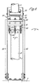
- Part l4 ( Figure 2 and 3) is welded to the other end l6 of the first flexible tube l2 and comprises a flange member l7 having a circumferentially extending spigot l8, three pin locating holes l9 through the flange member and equidistantly spaced apart, and a face 20 on the opposite side of the flange member to the circumferentially extending spigot which is at an angle of approximately 5° to a plane P lying normal to the longitudinal axis A of the coupling.
- Part l5 ( Figures 4 to 6) of the coupling ll is welded to the other end 2l of the second flexible tube l3 and comprises a flange member 22 having a circumferentially extending recess 23, three protruding pins 24, equidistantly spaced apart, and a spring clip 25 positioned adjacent each protruding pin.
- Each spring clip 25 includes a handle 26 which is pivotally mounted at one end 27 about an axis B, and a substantially U-shaped spring member 28.
- Each spring membher 28 is pivotally mounted at the free ends 29 of its arms 30 about an axis C, and includes a helical coil spring 3l in each arm, and a spring strap 32 extending between the arms at the end remote from the free ends 29.
- the axis C is positioned nearer the free end 33 of the handle 26 than the axis B, and, when the handle is resting against the part l5 of the coupling ll (the lock position), axis C is positioned nearer the second flexible tube 13 than the axis B.
- the spring clips 25 provide the fastening means to secure the two parts l4,l5 of the coupling ll together, and, in this configuration, have an over-centre locking mechanism.
- the holes l9 in flange member l7 are sized and positioned to receive the protruding pins 24 in flange member 22, the length of each protruding pin being greater than the length of the corresponding hole.
- the circumferentially extending recess 23 in flange member 22 is sized to receive the circumferentially extending spigot l8 of flange member l7 in a substantially gas-tight seal when the two parts l4,l5 of the coupling ll are releasably secured together.
- the two parts l4,l5 are releasably secured together by pivoting the handle 26 about its axis B such that the free end 33 of the handle moves away the second flexible tube l3.
- the two parts l4,l5 are then pushed together so that the circumferentially extending spigot l7 fully enters the circumferentially extending recess 23, and the protruding pins 24 pass through the pin receiving holes l9 to protrude from face 20.
- each spring clip 25 is then positioned against the face 20 below its respective protruding pin 24, and the free end 33 of each handle 26 moved back towards the second flexible tube l3 until each handle rests against the part l5 of the coupling ll and each spring strap 32 engages its respective protruding pin 24, thereby releasably securing the two parts l4,l5 together (Figure 7).
- the connection between the end 8 of the first flexible tube l2 and the first rigid portion 5 comprises a first spherical bearing 34.
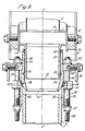
- the first spherical bearing 34 comprises three tubular members 35,36,37.
- the first tubular member 35 ( Figure 9) is welded to the end 8 of the first flexible tube l2 and has an internal surface 38 of frustoconical shape at its free end 39.
- the second tubular member 36 is attached to the first tubular member 35 by resilient means 40 comprising two metal ring 4l,42, three threaded nuts 43 and studs 44, and three coil springs 45.
- Metal ring 4l is integral with the first tubular member 35, and metal ring 42 is welded to the second tubular member 36.
- the studs 44 pass through apertures 62 ( Figure 2) in the metal rings 4l,42, are equidistantly spaced apart, and have nuts 43 threaded on each end.
- a coil spring 45 is positioned about each stud 44 between the metal ring 4l and the adjacent nut 43.
- the second tubular member 36 has an external surface 46 of truncated hemispherical shape at one end 47 which is shaped and sized to partially fit into the internal surface 38 of the first tubular member.
- Two tapered sealing rings 48 are positioned in grooves 49 in the internal surface 38 and engage the external surface 46.
- Metal ring 42 is also rigidly secured by support members 50 ( Figure 8) to the rear part 3 of the articulated motor vehicle.
- the tension applied by the coil springs 45 to move the first tubular member 35 towards the second tubular member 36 can be adjusted, thereby providing the resilient means 40 for attaching the second tubular member to the first tubular member.
- the tension applied by the coil springs 45 is set such that a substantially gas-tight seal is formed by the tapered sealing ring 48 between the first tubular member 35 and the second tubular member 36, and such as to allow for limited oscillatory movement in the direction indicated by arrows D between the first tubular member 35 and second tubular member 36.
- the third tubular member 37 is rigidly secured to the front part 2 of the articulated motor vehicle by a support bracket 6l, and is clamped (not shown) at one end 5l to the first rigid portion 5 of the exhaust pipe system.
- the other end 52 of the third tubular member 37 is positioned inside the second tubular member 36.
- Two sealing rings 53 are positioned in grooves 54 in the inner surface 55 of the second tubular member 36 which contact the external surface 56 of the third tubular member 37.
- This arrangement is such that a substantially gas-tight seal is formed between the second tubular member 36 and the third tubular member 37, and such that limited rotational movement is allowed between the second tubular member 36 and the third tubular member 37 about the longitudinal axis E of the first spherical bearing 34.
- the first spherical bearing 34 provides conpensation for the relative pivotal movement (above pivot 4), and for relative oscillatory movement (in direction D), between the front part 2 and rear part 3 of the articulated motor vehicle.
- the connection between the end 9 of the second flexible tube l3 and the second rigid portion 6 is made by a second spherical bearing 57.
- the second spherical bearing 57 comprises two tubular member 58,59 which are substantially identical to the first and second tubular members 35,36 respectively of the first spherical bearing 34; and resilient means 60 which is substantially identical to resilient means 40.
- tubular member 58 is welded to the end 9 of the second flexible tube l3, and tubular member 59 is permanently attached to the second rigid portion 6.
- Tapered sealing rings (not shown) are positioned between the tubular members 58,59 in the same way as the tapered sealing rings 48 in the first spherical bearing 34.
- the second spherical bearing 57 allows for other limited oscillatory movements between the front parts 2 and the rear part 3 of the articulated motor vehicle.
- the present invention therefore provides an exhaust pipe system for an articulated motor vehicle which has an intermediate flexible portion between the rigid portions of the exhaust pipe system attached to each part of the vehicle, the intermediate flexible portion including a coupling comprising two parts which are releasably secured together and which separate when a force above a predetermined level is applied between them.
- the force is usually a combination of both axial tensile force and bending about the coupling.
- the arrangement is such that the two parts of the coupling are secured together with a substantially gas-tight seal during normal operation of the vehicle, but will separate if one part of the vehicle rolls over.
- the coupling described in the above preferred embodiment has the added advantages that on separation of the parts of the coupling, no excessive strain is applied to other parts of the exhaust pipe system, thereby avoiding fatigue and/or damage, and that there are no loose parts which could otherwise be lost on separation.
Landscapes
- Engineering & Computer Science (AREA)
- Mechanical Engineering (AREA)
- General Engineering & Computer Science (AREA)
- Chemical & Material Sciences (AREA)
- Combustion & Propulsion (AREA)
- Transportation (AREA)
- Exhaust Silencers (AREA)
- Joints Allowing Movement (AREA)
- Quick-Acting Or Multi-Walled Pipe Joints (AREA)
Applications Claiming Priority (2)
| Application Number | Priority Date | Filing Date | Title |
|---|---|---|---|
| GB8523308 | 1985-09-20 | ||
| GB08523308A GB2180609A (en) | 1985-09-20 | 1985-09-20 | Exhaust pipe system |
Publications (2)
| Publication Number | Publication Date |
|---|---|
| EP0217531A2 true EP0217531A2 (fr) | 1987-04-08 |
| EP0217531A3 EP0217531A3 (fr) | 1988-07-20 |
Family
ID=10585506
Family Applications (1)
| Application Number | Title | Priority Date | Filing Date |
|---|---|---|---|
| EP86306492A Withdrawn EP0217531A3 (fr) | 1985-09-20 | 1986-08-21 | Système de tuyau d'échappement |
Country Status (3)
| Country | Link |
|---|---|
| US (1) | US4719752A (fr) |
| EP (1) | EP0217531A3 (fr) |
| GB (1) | GB2180609A (fr) |
Cited By (1)
| Publication number | Priority date | Publication date | Assignee | Title |
|---|---|---|---|---|
| EP2365240A1 (fr) * | 2010-03-12 | 2011-09-14 | PlymoVent AB | Couplage sécurisé pour système d'extraction d'émissions de véhicule |
Families Citing this family (15)
| Publication number | Priority date | Publication date | Assignee | Title |
|---|---|---|---|---|
| GB8902182D0 (en) * | 1989-02-01 | 1989-03-22 | Eminox Ltd | Mounting system |
| JP3451706B2 (ja) * | 1993-07-09 | 2003-09-29 | マツダ株式会社 | エンジンの排気装置 |
| US5832726A (en) * | 1997-01-24 | 1998-11-10 | Cooper Cameron Corporation | Internal combustion engine assembly |
| US6164062A (en) * | 1999-01-22 | 2000-12-26 | Caterpillar Inc. | Exhaust system for an internal combustion engine and shield arrangement therefor |
| DE10128949A1 (de) * | 2001-06-19 | 2003-07-10 | Faurecia Abgastechnik Gmbh | Abgasklappe |
| US7273413B2 (en) * | 2004-03-01 | 2007-09-25 | Robert Frink | Vehicle exhaust system hose and coupling assembly |
| US7717205B2 (en) * | 2006-11-28 | 2010-05-18 | Caterpillar Inc. | Engine hood assembly enclosure with exhaust aftertreatment device integrated therein, and machine using same |
| US7926604B2 (en) * | 2006-12-19 | 2011-04-19 | International Truck Intellectual Property Company, Llc | Electrical harness clipping bar for aftertreatment device |
| SE530776C2 (sv) * | 2007-01-18 | 2008-09-09 | Nederman Philip & Co Ab | Säkerhetskoppling |
| US7971676B2 (en) * | 2007-10-26 | 2011-07-05 | Dusa Ii James R | Exhaust system protection device |
| US8453784B2 (en) | 2007-10-26 | 2013-06-04 | II James R. Dusa | Exhaust system protection device |
| US20100314504A1 (en) * | 2009-06-12 | 2010-12-16 | Volvo Group North America, Inc. | Support apparatus for an exhaust system |
| US20110036130A1 (en) * | 2009-08-17 | 2011-02-17 | Karla Jean Hisler | Catalytic converter theft deterrent device |
| US11913642B2 (en) * | 2020-07-29 | 2024-02-27 | E2Comply, Llc | Apparatus, methods, and systems for providing a modular tubular exhaust |
| US11713706B2 (en) * | 2021-03-17 | 2023-08-01 | William Todd | Catalytic converter anti-theft devices and systems |
Family Cites Families (18)
| Publication number | Priority date | Publication date | Assignee | Title |
|---|---|---|---|---|
| US152413A (en) * | 1874-06-23 | Improvement in couplings for air and steam brakes | ||
| US426824A (en) * | 1890-04-29 | Edwin a | ||
| US930933A (en) * | 1909-02-18 | 1909-08-10 | Christopher Grey | Steam-pipe coupling for cars. |
| DE672947C (de) * | 1937-01-18 | 1939-03-13 | Magneti Marelli Spa | Loesbare Kupplung fuer Rohrleitungen von Fahrzeugen |
| GB530038A (en) * | 1939-07-18 | 1940-12-03 | Malcolm Edward Johnson | Improvements in servomotor brake pipe couplings for vehicles |
| US2502753A (en) * | 1946-08-17 | 1950-04-04 | Fred H Rohr | Flexible joint and flexible universal joint |
| US2533640A (en) * | 1947-10-25 | 1950-12-12 | Raymond M Ulrich | Quick disconnect hydraulic coupler |
| GB715160A (en) * | 1951-05-21 | 1954-09-08 | Bendix Aviat Corp | Improvements in or relating to quick-release pipe couplings |
| GB761017A (en) * | 1954-09-23 | 1956-11-07 | Automotive Prod Co Ltd | Improvements in or relating to hose coupling devices |
| FR1184375A (fr) * | 1956-11-20 | 1959-07-21 | Athey Products Corp | Benne basculante chauffée pour véhicules de transport de matériaux gluants |
| FR1342897A (fr) * | 1962-10-01 | 1963-11-15 | Dispositif de raccordement rapide pour tuyaux, tubes ou analogues | |
| US3152815A (en) * | 1963-06-03 | 1964-10-13 | Barragato Achille Robert | Intra vehicle mechanical connector |
| FR1478343A (fr) * | 1965-07-07 | 1967-04-28 | Faiveley Sa | Dispositif permettant l'accouplement pneumatique et électrique de véhicules de chemin de fer |
| FR2316435A1 (fr) * | 1975-07-04 | 1977-01-28 | Peugeot | Perfectionnement aux dispositifs d'echappement des gaz d'un moteur a combustion |
| HU173328B (hu) * | 1976-12-22 | 1979-04-28 | Gany Mavag Mozdony Vagon Es Ge | Sfericheskoe sharnirnoe soedinenie trub mezhdu detaljami mashin, peremehhajuhhikhsja po otnosheniju drug-drugu vo vremja ehksploatacii |
| US4339919A (en) * | 1980-03-24 | 1982-07-20 | Towmotor Corporation | Flexible muffler mounting |
| US4392513A (en) * | 1981-02-09 | 1983-07-12 | Parrish Reuel C | Quick disconnect safety coupling |
| JPS58128934A (ja) * | 1982-01-27 | 1983-08-01 | Tokyu Car Corp | ダンプトレ−ラの荷台凍結防止装置 |
-
1985
- 1985-09-20 GB GB08523308A patent/GB2180609A/en not_active Withdrawn
-
1986
- 1986-08-21 EP EP86306492A patent/EP0217531A3/fr not_active Withdrawn
- 1986-09-18 US US06/909,000 patent/US4719752A/en not_active Expired - Fee Related
Cited By (6)
| Publication number | Priority date | Publication date | Assignee | Title |
|---|---|---|---|---|
| EP2365240A1 (fr) * | 2010-03-12 | 2011-09-14 | PlymoVent AB | Couplage sécurisé pour système d'extraction d'émissions de véhicule |
| WO2011110641A3 (fr) * | 2010-03-12 | 2012-01-19 | Plymovent Ab | Accouplement de sûreté pour système d'échappement de véhicule |
| CN102884356A (zh) * | 2010-03-12 | 2013-01-16 | 普利美有限公司 | 用于车辆废气排出系统的安全联接器 |
| CN102884356B (zh) * | 2010-03-12 | 2015-04-01 | 普利美尾气抽排有限公司 | 安全联接器组件和包括其的车辆废气排出系统 |
| RU2557149C2 (ru) * | 2010-03-12 | 2015-07-20 | Плюмовент Экзост Экстракшн Б.В. | Предохранительная муфта для системы отбора выхлопных газов транспортного средства |
| US9739405B2 (en) | 2010-03-12 | 2017-08-22 | Plymovent Exhaust Extraction B.V. | Safety coupling for vehicle exhaust extraction system |
Also Published As
| Publication number | Publication date |
|---|---|
| GB2180609A (en) | 1987-04-01 |
| GB8523308D0 (en) | 1985-10-23 |
| US4719752A (en) | 1988-01-19 |
| EP0217531A3 (fr) | 1988-07-20 |
Similar Documents
| Publication | Publication Date | Title |
|---|---|---|
| EP0217531A2 (fr) | Système de tuyau d'échappement | |
| US4156436A (en) | Support system for flexible conduits | |
| AU597015B2 (en) | Flexible joint for connecting two axially spaced pipes in an engine exhaust system | |
| US5713592A (en) | Apparatus for supporting vehicle conduit | |
| US6854561B2 (en) | Hanger systems and methods | |
| CA1266165A (fr) | Support universel | |
| US5024283A (en) | Pivotable, resilient mounting | |
| US5927108A (en) | Wheel lock | |
| US4077597A (en) | Mirror | |
| JPH0565986A (ja) | ホース連結用アダプタ | |
| US4286309A (en) | Detachable vehicle lighting fixture | |
| US5791610A (en) | Quick release bow rack | |
| US3960232A (en) | Exhaust system mounting | |
| US4180230A (en) | Hanger for vehicle mud flaps | |
| US5150911A (en) | Tow bar assembly | |
| US3989269A (en) | Sway control devices utilizable in conjunction with equalizer hitches | |
| WO1995003506A1 (fr) | Joint de conduit d'echappement pour vehicule, flexible dans toutes les directions | |
| US4251096A (en) | Bumper and fixings | |
| US7481595B2 (en) | Ball joint | |
| US4073461A (en) | Fender-mount rear view mirror support | |
| US6663126B2 (en) | Bicycle trailer hitch | |
| AU2022331205B2 (en) | Cable routing device | |
| US6116483A (en) | Spare wheel mounting bracket | |
| EP0853011A1 (fr) | Stabilisateur pour ressort à lame. | |
| US5048376A (en) | Tool, mounting means and ring device for anti-skid chains |
Legal Events
| Date | Code | Title | Description |
|---|---|---|---|
| PUAI | Public reference made under article 153(3) epc to a published international application that has entered the european phase |
Free format text: ORIGINAL CODE: 0009012 |
|
| 17P | Request for examination filed |
Effective date: 19860828 |
|
| AK | Designated contracting states |
Kind code of ref document: A2 Designated state(s): AT BE CH DE FR GB IT LI LU NL SE |
|
| PUAL | Search report despatched |
Free format text: ORIGINAL CODE: 0009013 |
|
| AK | Designated contracting states |
Kind code of ref document: A3 Designated state(s): AT BE CH DE FR GB IT LI LU NL SE |
|
| STAA | Information on the status of an ep patent application or granted ep patent |
Free format text: STATUS: THE APPLICATION IS DEEMED TO BE WITHDRAWN |
|
| 18D | Application deemed to be withdrawn |
Effective date: 19890121 |
|
| RIN1 | Information on inventor provided before grant (corrected) |
Inventor name: HALL, ANDREW WILLIAM |