EP0217604A2 - Spleissen optischer Fasern - Google Patents
Spleissen optischer Fasern Download PDFInfo
- Publication number
- EP0217604A2 EP0217604A2 EP86307222A EP86307222A EP0217604A2 EP 0217604 A2 EP0217604 A2 EP 0217604A2 EP 86307222 A EP86307222 A EP 86307222A EP 86307222 A EP86307222 A EP 86307222A EP 0217604 A2 EP0217604 A2 EP 0217604A2
- Authority
- EP
- European Patent Office
- Prior art keywords
- optical fibre
- clamping device
- splice
- splicing
- optical fibres
- Prior art date
- Legal status (The legal status is an assumption and is not a legal conclusion. Google has not performed a legal analysis and makes no representation as to the accuracy of the status listed.)
- Withdrawn
Links
- 239000013307 optical fiber Substances 0.000 title claims abstract description 47
- 230000003287 optical effect Effects 0.000 claims abstract description 47
- 239000004033 plastic Substances 0.000 abstract description 5
- 229920003023 plastic Polymers 0.000 abstract description 5
- 230000004927 fusion Effects 0.000 description 8
- 230000000712 assembly Effects 0.000 description 3
- 238000000429 assembly Methods 0.000 description 3
- 239000000853 adhesive Substances 0.000 description 1
- 230000001070 adhesive effect Effects 0.000 description 1
- 239000011248 coating agent Substances 0.000 description 1
- 238000000576 coating method Methods 0.000 description 1
- 239000000835 fiber Substances 0.000 description 1
- 238000007526 fusion splicing Methods 0.000 description 1
Images
Classifications
-
- G—PHYSICS
- G01—MEASURING; TESTING
- G01N—INVESTIGATING OR ANALYSING MATERIALS BY DETERMINING THEIR CHEMICAL OR PHYSICAL PROPERTIES
- G01N3/00—Investigating strength properties of solid materials by application of mechanical stress
- G01N3/08—Investigating strength properties of solid materials by application of mechanical stress by applying steady tensile or compressive forces
- G01N3/14—Investigating strength properties of solid materials by application of mechanical stress by applying steady tensile or compressive forces generated by dead weight, e.g. pendulum; generated by springs tension
-
- G—PHYSICS
- G02—OPTICS
- G02B—OPTICAL ELEMENTS, SYSTEMS OR APPARATUS
- G02B6/00—Light guides; Structural details of arrangements comprising light guides and other optical elements, e.g. couplings
- G02B6/24—Coupling light guides
- G02B6/255—Splicing of light guides, e.g. by fusion or bonding
- G02B6/2551—Splicing of light guides, e.g. by fusion or bonding using thermal methods, e.g. fusion welding by arc discharge, laser beam, plasma torch
-
- G—PHYSICS
- G02—OPTICS
- G02B—OPTICAL ELEMENTS, SYSTEMS OR APPARATUS
- G02B6/00—Light guides; Structural details of arrangements comprising light guides and other optical elements, e.g. couplings
- G02B6/24—Coupling light guides
- G02B6/36—Mechanical coupling means
- G02B6/38—Mechanical coupling means having fibre to fibre mating means
- G02B6/3801—Permanent connections, i.e. wherein fibres are kept aligned by mechanical means
-
- G—PHYSICS
- G01—MEASURING; TESTING
- G01N—INVESTIGATING OR ANALYSING MATERIALS BY DETERMINING THEIR CHEMICAL OR PHYSICAL PROPERTIES
- G01N2203/00—Investigating strength properties of solid materials by application of mechanical stress
- G01N2203/003—Generation of the force
- G01N2203/0032—Generation of the force using mechanical means
- G01N2203/0035—Spring
-
- G—PHYSICS
- G01—MEASURING; TESTING
- G01N—INVESTIGATING OR ANALYSING MATERIALS BY DETERMINING THEIR CHEMICAL OR PHYSICAL PROPERTIES
- G01N2203/00—Investigating strength properties of solid materials by application of mechanical stress
- G01N2203/02—Details not specific for a particular testing method
- G01N2203/026—Specifications of the specimen
- G01N2203/0262—Shape of the specimen
- G01N2203/0278—Thin specimens
-
- G—PHYSICS
- G01—MEASURING; TESTING
- G01N—INVESTIGATING OR ANALYSING MATERIALS BY DETERMINING THEIR CHEMICAL OR PHYSICAL PROPERTIES
- G01N2203/00—Investigating strength properties of solid materials by application of mechanical stress
- G01N2203/02—Details not specific for a particular testing method
- G01N2203/026—Specifications of the specimen
- G01N2203/0262—Shape of the specimen
- G01N2203/0278—Thin specimens
- G01N2203/028—One dimensional, e.g. filaments, wires, ropes or cables
Definitions
- This invention relates to end-to-end splicing of optical fibres.
- the invention is especially concerned with fusion splicing of optical fibres but it is to be understood that the invention is also applicable to splicing of fibres by means of an index matching adhesive.
- optical fibre splice mechanical testing apparatus comprising two optical fibre clamping devices which are adapted to be permanently or detachably mounted on splicing equipment at positions spaced lengthwise of two optical fibres to be spliced and located on opposite sides of the splicing station, at least one of which clamping devices is constrained to move towards or away from the other clamping device in a direction lengthwise of said optical fibres between a first position nearer the the splicing station and a second position remote from the splicing station and is urged towards said second position by spring means and, associated with said movable clamping device, adjustable means for temporarily maintaining said movable clamping device in said first position against the action of said spring means, the arrangement being such that, after splicing of two optical fibres has been effected, the movable clamping device is temporarily maintained in said first position against the action of said spring means, the clamping devices are clamped to the optical fibres, and the adjustable means is
- protection is applied to an optical fibre splice after the splice has been effected and, for this purpose, it has been the practice for an operator to remove spliced optical fibres from the splicing station and to place the splice in a station where such protection can be applied.
- the optical fibre splice mechanical testing apparatus of the present invention can also be employed to transfer spliced optical fibres from the splicing station to a station at which protection can be applied to the splice, without any manhandling of the spliced optical fibres by an operator, thereby substantially reducing risk of any damage to the splice.
- the clamping devices are carried by a common support structure which can be so adjustably mounted on optical fibre splicing equipment that, after the splice between optical fibres clamped in the clamping devices has been mechanically tested and found satisfactory, the spliced optical fibres while still clamped by said clamping devices can be readily transferred to the splice protection-application station.
- the clamping devices are mounted at longitudinally spaced positions on a common shaft which extends lengthwise of and is transversely spaced from the splicing station and which is constrained to pivot about its longitudinal axis between a position in which spliced optical fibres in the splicing station are clamped in the clamping devices to a position in which said spliced optical fibres still clamped in the clamping devices are located in the splice protection-application station.
- Each clamping device preferably comprises an elongate member which, at one of its ends, is mounted on the shaft and which, at the other of its ends, carries a pair of adjustable jaws between which an optical fibre can be clamped.
- Pivotable movement of the shaft on which the clamping devices are mounted is preferably effected by means of a system of levers and an associated adjustable stop by means of which the length of the arcuate path followed by the clamping devices when the shaft is pivoted can be readily adjusted.
- the movable clamping device preferably is keyed to and slidably mounted on the shaft and the spring means urging the movable clamping device towards said second position preferably is a coil spring which extends between the movable clamping device and a stop which is secured to the shaft and through which the shaft extends.
- the adjustable means for temporarily maintaining the movable clamping device in said first position against the action of the coil spring may take any convenient form but, in its simplest form, preferably comprises a sleeve which is slidably mounted on the shaft on the side of the movable clamping device remote from the coil spring and which is keyed to the shaft by means of bayonet-like fitting similar to that employed in sockets for the reception of electric light bulbs.
- the sleeve may be in screw threaded engagement with the shaft so that, as the sleeve is unwound and the movable clamping device moves towards said second position under the action of the coil spring, a tensile force is gradually applied to the splice.
- the optical fibre splice mechanical testing apparatus may include means for effecting all operations of the apparatus in sequence automatically.
- the invention also includes optical fibre splicing equipment incorporating optical fibre splice mechanical testing apparatus as hereinbefore described.
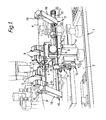
- optical fibre splicing equipment 1 includes a housing 2 on which optical fibre clamping assemblies 3 are positioned on opposite sides of a pair of electrodes 5 by means of which a fusion splice between two aligned optical fibres F can be effected and which constitute a splicing station 4. Also mounted on the housing 2 is a splice support table 7 in the upper surface of which is a splice support groove 8 and which constitutes a splice protection-application station 6 at which a heat-shrinkable plastics sleeve, positioned on a fusion splice between two aligned optical fibres, can be heated to cause it to shrink around the fusion splice.
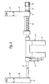
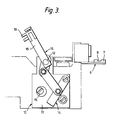
- the apparatus 10 comprises a block 11, a shaft 12 which is mounted in the block and extends substantially parallel to optical fibres F to be spliced by the optical fibre splicing equipment 1 and which is pivotable about its longitudinal axis by means of a system 14 of levers, and an associated adjustable stop 15 by means of which the extent of pivotal movement of the shaft about its longitudinal axis can be readily adjusted.
- two optical fibres clamping devices 16 and 17 each of which comprises an elongate member 18 which, at one of its ends is mounted on the shaft and which, at the other of its ends, carries a pair of adjustable jaws 19 between which an optical fibre can be clamped.
- the adjustable jaws 19 are spring loaded sufficiently enough to grip an optical fibre F without causing any damage to any coating on the fibre.
- the elongate member 18 of the clamping device 17 is constrained to move towards or away from the clamping device 16 in a direction lengthwise of the shaft 12 between a first position nearer the splicing station 4 and a second position remote from the splicing station and is urged towards the second position by a coil spring 20 which extends between the clamping device 17 and a stop 23 which is secured to the shaft and through which the shaft extends.
- Adjustable means for temporarily maintaining the movable clamping device 17 in the first position against the action of the coil spring 20 comprises a sleeve 21 which is slidably mounted on the shaft 12 on the side of the movable clamping device 17 remote from the coil spring 20 and which is keyed to the shaft by means of a bayonet-like fitting similar to that employed in sockets for the reception of electric light bulbs.
- Manipulation of the sleeve 21 can be effected by a knurled cap 22.
- the adjustable stop 15 will be so adjusted that the shaft 12 is pivotable about its longitudinal axis from a first position in which spliced optical fibres in the splicing station 4 are clamped in the clamping devices 16, 17 to a second position in which said spliced optical fibres still clamped in the clamping devices are located in the splice protection-application station 6.
- a heat-shrinkable plastics sleeve (not shown) is slipped over one of two optical fibres F to be spliced, the optical fibres F are aligned in the clamping assemblies 3 of the optical fibre splicing equipment 1 with their end faces substantially abutting at the splicing station 4 and the fusion splice between the aligned optical fibres is effected.
- the shaft 12 With the spring loaded jaws 19 of the clamping devices 16, 17 open and with the movable clamping device 17 urged to the first position nearer the splicing station 4 against the action of the coil spring 20 by means of the sleeve 21, the shaft 12 is caused to pivot about its longitudinal axis to the first position in which the spliced optical fibres F pass through the open jaws of the clamping devices, the heat-shrinkable plastics sleeve being positioned between the splice and one of the clamping devices.
- the spring loaded jaws 19 of the clamping devices 16, 17 are then actuated to cause the clamping devices to grip the spliced optical fibres.
- the spliced optical fibres F are then released from the optical fibre clamping assemblies 3 of the splicing equipment 1 and the shaft 12 is pivoted about its longitudinal axis to withdraw the spliced optical fibres from the splicing station 4 to a position intermediate the splicing station and the splice protection-application station 6.
- the locking sleeve 21 is then released so that the movable clamping device 17 is urged in a direction away from the clamping device 16 by means of the coil spring 20 to impart a predetermined tensile force on the fusion splice between the optical fibres.
- the heat-shrinkable plastics sleeve is slid over the fusion splice and further pivotal movement of the shaft 12 is effected to the second position in which the spliced optical fibres F still clamped in the clamping devices 16, 17, are located in the splice protection-application station 6.
- the heat-shrinkable sleeve is heated to cause it to shrink on to the fusion splice and when this has been completed the optical fibres are released from the jaws 19 of the clamping devices 16, 17.
Landscapes
- Physics & Mathematics (AREA)
- General Physics & Mathematics (AREA)
- Engineering & Computer Science (AREA)
- Plasma & Fusion (AREA)
- Optics & Photonics (AREA)
- Life Sciences & Earth Sciences (AREA)
- Health & Medical Sciences (AREA)
- Chemical & Material Sciences (AREA)
- Analytical Chemistry (AREA)
- Biochemistry (AREA)
- General Health & Medical Sciences (AREA)
- Immunology (AREA)
- Pathology (AREA)
- Mechanical Coupling Of Light Guides (AREA)
Applications Claiming Priority (2)
| Application Number | Priority Date | Filing Date | Title |
|---|---|---|---|
| GB8523157 | 1985-09-19 | ||
| GB858523157A GB8523157D0 (en) | 1985-09-19 | 1985-09-19 | Optical fibre splicing |
Publications (2)
| Publication Number | Publication Date |
|---|---|
| EP0217604A2 true EP0217604A2 (de) | 1987-04-08 |
| EP0217604A3 EP0217604A3 (de) | 1988-08-03 |
Family
ID=10585424
Family Applications (1)
| Application Number | Title | Priority Date | Filing Date |
|---|---|---|---|
| EP86307222A Withdrawn EP0217604A3 (de) | 1985-09-19 | 1986-09-19 | Spleissen optischer Fasern |
Country Status (4)
| Country | Link |
|---|---|
| US (1) | US4736632A (de) |
| EP (1) | EP0217604A3 (de) |
| AU (1) | AU6298686A (de) |
| GB (2) | GB8523157D0 (de) |
Cited By (2)
| Publication number | Priority date | Publication date | Assignee | Title |
|---|---|---|---|---|
| EP1130430A4 (de) * | 1999-09-09 | 2003-01-15 | Furukawa Electric Co Ltd | Schutzummantelungsmechanismus für ein glasfaserschnelzsplei gerät |
| CN1329758C (zh) * | 2002-07-03 | 2007-08-01 | 菲特尔美国公司 | 减小光纤中拼接损耗的系统和方法 |
Families Citing this family (27)
| Publication number | Priority date | Publication date | Assignee | Title |
|---|---|---|---|---|
| JPH0675023B2 (ja) * | 1988-01-30 | 1994-09-21 | 株式会社フジクラ | 光ファイバの接続損失推定法 |
| US4840450A (en) * | 1988-02-03 | 1989-06-20 | General Electric Company | Apparatus and method for optical fiber end positioning for laser injection |
| US5002351A (en) * | 1988-07-05 | 1991-03-26 | Preformed Line Products Company | Fusion splicer for optical fibers |
| US5170456A (en) * | 1988-09-07 | 1992-12-08 | Fujikura Ltd. | Apparatus for aligning a plurality of single-fiber cables |
| US5046813A (en) * | 1988-09-07 | 1991-09-10 | Fujikura Ltd. | Method and apparatus for aligning a plurality of single-fiber cables, and method of simultaneously fusion-splicing such cables |
| JP2951359B2 (ja) * | 1989-04-20 | 1999-09-20 | 古河電気工業株式会社 | 光ファイバ用被覆除去装置 |
| JPH0752149B2 (ja) * | 1989-12-14 | 1995-06-05 | 日本電信電話株式会社 | セラミックス製割スリーブの試験装置 |
| JP2532281Y2 (ja) * | 1991-07-02 | 1997-04-09 | 住友電気工業株式会社 | ファイバ形カプラ製造装置 |
| GB9117761D0 (en) * | 1991-08-16 | 1991-10-02 | Bicc Plc | Optical fibre splicing |
| DE4131670C2 (de) * | 1991-09-23 | 1994-09-29 | Stein Herbert Textechno | Zugprüfgerät sowie Verfahren zum Durchführen von Zugversuchen an verdrallten Prüfmaterialien |
| US5187767A (en) * | 1992-05-14 | 1993-02-16 | Northern Telecom Limited | Optical fiber prooftester and method for its use |
| GB2271433A (en) * | 1992-10-08 | 1994-04-13 | David Lister Myers | Optical fibre fusion splicing with reciprocal movement |
| US5386490A (en) * | 1993-07-01 | 1995-01-31 | E-Tek Dynamics, Inc. | Automated workstation for the manufacture of optical fiber couplers |
| CA2116934C (en) * | 1994-03-03 | 2000-08-01 | Murray R. Harman | Method for controlling the contact of optical fibers |
| US5481640A (en) * | 1994-06-27 | 1996-01-02 | Fiberlign Division Of Preformed Line Products (Canada) Ltd. | Tool for fusing optical fibers |
| US5717813A (en) * | 1994-06-27 | 1998-02-10 | Fiberlign A Division Of Preformed Line Products (Canada) Ltd. | Fusion splice element for use in splicing optical fibers |
| US5740301A (en) * | 1994-06-27 | 1998-04-14 | Fiberlign Division Of Preformed Line Products Ltd. | Fusion splicing block with electrodes disposed on planar surface |
| DE19714718A1 (de) * | 1997-04-09 | 1998-10-15 | Siemens Ag | Spleißschutz und Aufnahmevorrichtung für Lichtwellenleiter sowie Anordnung zum Einlegen der Lichtwellenleiter in den Spleißschutz |
| US6088503A (en) * | 1998-02-02 | 2000-07-11 | Ciena Corporation | Optical fiber precision handling tool |
| SE9901493D0 (sv) * | 1999-04-26 | 1999-04-26 | Ericsson Telefon Ab L M | Fibersvetsningsapparat med uppvärmningsanordning |
| US6334007B1 (en) | 2000-04-13 | 2001-12-25 | Amherst Holding Co. | Optical fiber pull tester having an acoustic sensor |
| SE519520C2 (sv) * | 2000-11-29 | 2003-03-11 | Ericsson Telefon Ab L M | Dragprovmaskin för optiska fibrer |
| SE526483C2 (sv) * | 2003-09-05 | 2005-09-20 | Ericsson Telefon Ab L M | Förfarande och anordning för att minimera överskott av fiberkabel |
| CN101819297B (zh) * | 2010-04-23 | 2011-08-17 | 哈尔滨工业大学 | 一种用于光纤耦合器制作的熔融拉伸机构 |
| CN103009052B (zh) * | 2013-01-11 | 2014-12-31 | 山东太平洋光缆有限公司 | 光纤活动连接器内衬套自动压接机 |
| JP6554734B2 (ja) * | 2015-03-10 | 2019-08-07 | Seiオプティフロンティア株式会社 | 光ファイバの融着接続方法および融着接続装置 |
| CN111580224B (zh) * | 2020-06-23 | 2024-10-22 | 四川华拓光通信股份有限公司 | 一种快速测试用可插拔光纤端口的弹性辅助装置 |
Family Cites Families (4)
| Publication number | Priority date | Publication date | Assignee | Title |
|---|---|---|---|---|
| FR2445972A1 (fr) * | 1979-01-03 | 1980-08-01 | Lyonnaise Transmiss Optiques | Dispositif de soudage de plusieurs fibres optiques bout a bout par nappes et procede de soudage a l'aide de ce dispositif |
| US4274707A (en) * | 1979-06-14 | 1981-06-23 | Northern Telecom Limited | Apparatus for fusion splicing of optical fibers |
| JPS6051807A (ja) * | 1983-08-31 | 1985-03-23 | Fujitsu Ltd | 光フアイバ−接続部の収容方法 |
| IT1173154B (it) * | 1984-01-27 | 1987-06-18 | Pirelli Cavi Spa | Metodo per giuntare due fibre ottiche e giunzione cosi' ottenuta |
-
1985
- 1985-09-19 GB GB858523157A patent/GB8523157D0/en active Pending
-
1986
- 1986-09-15 US US06/907,657 patent/US4736632A/en not_active Expired - Fee Related
- 1986-09-17 AU AU62986/86A patent/AU6298686A/en not_active Abandoned
- 1986-09-19 GB GB8622641A patent/GB2180668B/en not_active Expired
- 1986-09-19 EP EP86307222A patent/EP0217604A3/de not_active Withdrawn
Cited By (2)
| Publication number | Priority date | Publication date | Assignee | Title |
|---|---|---|---|---|
| EP1130430A4 (de) * | 1999-09-09 | 2003-01-15 | Furukawa Electric Co Ltd | Schutzummantelungsmechanismus für ein glasfaserschnelzsplei gerät |
| CN1329758C (zh) * | 2002-07-03 | 2007-08-01 | 菲特尔美国公司 | 减小光纤中拼接损耗的系统和方法 |
Also Published As
| Publication number | Publication date |
|---|---|
| US4736632A (en) | 1988-04-12 |
| GB8523157D0 (en) | 1985-10-23 |
| GB2180668A (en) | 1987-04-01 |
| GB8622641D0 (en) | 1986-10-22 |
| GB2180668B (en) | 1989-08-31 |
| EP0217604A3 (de) | 1988-08-03 |
| AU6298686A (en) | 1987-03-26 |
Similar Documents
| Publication | Publication Date | Title |
|---|---|---|
| US4736632A (en) | Optical fibre splicing | |
| CA1284047C (en) | Optical fibre breakout | |
| US5395025A (en) | Method and apparatus for angle cleaving ribbon fiber | |
| WO1998026314B1 (en) | Apparatus for, and method of, automated production, and/or packaging and/or testing of fiber optic devices including optical fiber system components and optical fibers | |
| DE69208497T2 (de) | Verspleissen von Glasfasern | |
| CA1270629A (en) | Fusion splicing optical fibre ribbon | |
| US5195157A (en) | Optical fibre splicing | |
| US4315584A (en) | Method and a device for separating a plurality of light waveguides carried in a cable | |
| EP0105909A4 (de) | Präzisionsspalten optischer fasern. | |
| US4607775A (en) | Device for cutting glass fibers | |
| US6643448B1 (en) | Optical fiber stripping tool | |
| US20170168240A1 (en) | An Optical Fiber Cleaving Device | |
| JP3951801B2 (ja) | 融着接続光ファイバの処理方法および搬送治具 | |
| DE3474291D1 (en) | Method and apparatus for cutting optical wave guides | |
| WO2000065388A1 (en) | Optical fiber splicing apparatus | |
| US20160091661A1 (en) | Portable Fiber Optic Splicer | |
| US4861133A (en) | Device for applying a splice protector to optical conductors | |
| US5323475A (en) | Optical connector | |
| US4927237A (en) | Universal night vision goggle adapter | |
| JP2001208931A (ja) | 光ファイバの融着接続方法と融着接続機および被覆除去器 | |
| JP2011191356A (ja) | 光ファイバの切断方法および切断装置 | |
| JP3122546B2 (ja) | 光ファイバの自動切断装置 | |
| JPS5824102A (ja) | 光フアイバの応力切断方法 | |
| US5187767A (en) | Optical fiber prooftester and method for its use | |
| WO2024122648A1 (en) | Optical fiber cutting device and optical fiber cutting method |
Legal Events
| Date | Code | Title | Description |
|---|---|---|---|
| PUAI | Public reference made under article 153(3) epc to a published international application that has entered the european phase |
Free format text: ORIGINAL CODE: 0009012 |
|
| AK | Designated contracting states |
Kind code of ref document: A2 Designated state(s): AT BE CH DE FR IT LI LU NL SE |
|
| 17P | Request for examination filed |
Effective date: 19870622 |
|
| PUAL | Search report despatched |
Free format text: ORIGINAL CODE: 0009013 |
|
| AK | Designated contracting states |
Kind code of ref document: A3 Designated state(s): AT BE CH DE FR IT LI LU NL SE |
|
| STAA | Information on the status of an ep patent application or granted ep patent |
Free format text: STATUS: THE APPLICATION HAS BEEN WITHDRAWN |
|
| 18W | Application withdrawn |
Withdrawal date: 19880927 |
|
| RIN1 | Information on inventor provided before grant (corrected) |
Inventor name: CASE, PETER GERARD |