EP0217605A2 - Système de conditionnement d'air - Google Patents
Système de conditionnement d'air Download PDFInfo
- Publication number
- EP0217605A2 EP0217605A2 EP86307225A EP86307225A EP0217605A2 EP 0217605 A2 EP0217605 A2 EP 0217605A2 EP 86307225 A EP86307225 A EP 86307225A EP 86307225 A EP86307225 A EP 86307225A EP 0217605 A2 EP0217605 A2 EP 0217605A2
- Authority
- EP
- European Patent Office
- Prior art keywords
- orifice
- air conditioning
- expansion valve
- conditioning system
- limit value
- Prior art date
- Legal status (The legal status is an assumption and is not a legal conclusion. Google has not performed a legal analysis and makes no representation as to the accuracy of the status listed.)
- Withdrawn
Links
Images

Classifications
-
- B—PERFORMING OPERATIONS; TRANSPORTING
- B60—VEHICLES IN GENERAL
- B60H—ARRANGEMENTS OF HEATING, COOLING, VENTILATING OR OTHER AIR-TREATING DEVICES SPECIALLY ADAPTED FOR PASSENGER OR GOODS SPACES OF VEHICLES
- B60H1/00—Heating, cooling or ventilating devices
- B60H1/00642—Control systems or circuits; Control members or indication devices for heating, cooling or ventilating devices
- B60H1/00814—Control systems or circuits characterised by their output, for controlling particular components of the heating, cooling or ventilating installation
- B60H1/00878—Control systems or circuits characterised by their output, for controlling particular components of the heating, cooling or ventilating installation the components being temperature regulating devices
- B60H1/00885—Controlling the flow of heating or cooling liquid, e.g. valves or pumps
-
- G—PHYSICS
- G05—CONTROLLING; REGULATING
- G05D—SYSTEMS FOR CONTROLLING OR REGULATING NON-ELECTRIC VARIABLES
- G05D9/00—Level control, e.g. controlling quantity of material stored in vessel
- G05D9/12—Level control, e.g. controlling quantity of material stored in vessel characterised by the use of electric means
-
- B—PERFORMING OPERATIONS; TRANSPORTING
- B60—VEHICLES IN GENERAL
- B60H—ARRANGEMENTS OF HEATING, COOLING, VENTILATING OR OTHER AIR-TREATING DEVICES SPECIALLY ADAPTED FOR PASSENGER OR GOODS SPACES OF VEHICLES
- B60H1/00—Heating, cooling or ventilating devices
- B60H1/00485—Valves for air-conditioning devices, e.g. thermostatic valves
-
- B—PERFORMING OPERATIONS; TRANSPORTING
- B60—VEHICLES IN GENERAL
- B60H—ARRANGEMENTS OF HEATING, COOLING, VENTILATING OR OTHER AIR-TREATING DEVICES SPECIALLY ADAPTED FOR PASSENGER OR GOODS SPACES OF VEHICLES
- B60H1/00—Heating, cooling or ventilating devices
- B60H1/00492—Heating, cooling or ventilating devices comprising regenerative heating or cooling means, e.g. heat accumulators
-
- F—MECHANICAL ENGINEERING; LIGHTING; HEATING; WEAPONS; BLASTING
- F25—REFRIGERATION OR COOLING; COMBINED HEATING AND REFRIGERATION SYSTEMS; HEAT PUMP SYSTEMS; MANUFACTURE OR STORAGE OF ICE; LIQUEFACTION SOLIDIFICATION OF GASES
- F25B—REFRIGERATION MACHINES, PLANTS OR SYSTEMS; COMBINED HEATING AND REFRIGERATION SYSTEMS; HEAT PUMP SYSTEMS
- F25B41/00—Fluid-circulation arrangements
- F25B41/30—Expansion means; Dispositions thereof
- F25B41/31—Expansion valves
- F25B41/315—Expansion valves actuated by floats
-
- F—MECHANICAL ENGINEERING; LIGHTING; HEATING; WEAPONS; BLASTING
- F25—REFRIGERATION OR COOLING; COMBINED HEATING AND REFRIGERATION SYSTEMS; HEAT PUMP SYSTEMS; MANUFACTURE OR STORAGE OF ICE; LIQUEFACTION SOLIDIFICATION OF GASES
- F25B—REFRIGERATION MACHINES, PLANTS OR SYSTEMS; COMBINED HEATING AND REFRIGERATION SYSTEMS; HEAT PUMP SYSTEMS
- F25B43/00—Arrangements for separating or purifying gases or liquids; Arrangements for vaporising the residuum of liquid refrigerant, e.g. by heat
- F25B43/006—Accumulators
Definitions
- This invention relates to an automobile air conditioning system having a variable capacity compressor.
- variable capacity compressors have been used for the purpose of improving the performance and effectiveness of automobile air conditioning systems. If a variable capacity compressor is used in an automobile air conditioning system, an accumulator should also be included in the refrigerating system. This is because, if a thermostatic automatic expansion valve is used in the refrigerating system in which the variable capacity compressor is included and the air conditioning load is small, the capacity of the compressor will be cyclically increased and decreased, i.e. a hunting phenomenon occurs. Therefore, it becomes difficult to control the refrigeration cycle.
- the automobile air conditioning system comprises a compressor 1 which is provided with a variable capacity mechanism, a condensor 2, an orifice tube 3, which serves as an expansion device, an evaporator 4 and an accumulator 5. These parts are serially connected with one another to form a closed refrigeration circuit.
- Compressed refrigerant discharged from the compressor 1 flows into the condensor 2 to allow the gaseous refrigerant to condense, and thereafter the refrigerant flows into the evaporator 4 through the orifice tube 3. Therefore, the compressed refrigerant is expanded while passing through the orifice tube 3.
- the expanded refrigerant is returned to the compressor 1 through the accumulator 5.
- the refrigerant in evaportator 4 is a mixture of gas and liquid, and the amount of refrigerant which must be enclosed in the refrigeration circuit is greater than that for a refrigeration circuit incorporating a thermostatic automatic expansion valve. Also, as the air conditioning load decreases, excess refrigerant is accumulated in the accumulator 5 and the volume of the accumulator 5 must therefore be larger as compared with the volume of a receiver tank of a refrigeration circuit incorporating a thermostatic automatic expansion valve. The accumulator 5 is needed to prevent liquid refrigerant from reaching the compressor 1. Thus, an automobile must be provided with sufficient space for the accumulator 5.
- an air conditioning system comprises a variable capacity compressor, a condensor, an expansion valve with an orifice of variable size, an evaporator, an accumulator and a control apparatus for controlling the size of the orifice of the expansion valve, and is characterized in that the control apparatus comprises sensor means for detecting the level of the surface of liquid refrigerant in the accumulator, comparison means for comparing the detected level of the liquid surface with a predetermined value, and control means for increasing and decreasing the size of the orifice of the expansion valve in response to the result of the comparison by the comparison means.
- the comparison means is arranged to compare the sensed level of the liquid surface with an upper limit value and a lower limit value
- the control means is arranged to increase and decrease the size of the orifice of the expansion value in response to the comparison means determining that the level of the liquid surface is below the lower limit value and above the upper limit value respectively.
- an automobile air conditioning system comprises a variable capacity compressor 10, a condensor 20, an electronic expansion valve 21, an evaporator 22 and an accumulator 23. These parts are serially connected with one another to form a closed refrigeration circuit.
- Compressed refrigerant gas at a high temperature is discharged from the compressor 10 and flows into the condensor 20 to be condensed to liquid refrigerant, which then enters the electronic expansion valve 21.
- the liquid refrigerant is reduced in pressure and expanded by the electronic expansion valve 21.
- the size of the orifice in the electronic expansion valve 21 through which the refrigerant flows is gradually changed under the control of a micro-computer.
- the refrigerant which has passed through the expansion valve 21 is a mixture of vapour and liquid.
- This refrigerant then enters the evaporator 22, where it is able to exchange heat with the air, causing some or all of the remaining liquid to be vaporized. However, if some of the liquid refrigerant is not vaporized and flows out from the evaporator 22, this refrigerant is collected in the accumulator 23 so that only gaseous refrigerant flows out of the evaporator 22 and back to the compressor 10.
- the accumulator 23 comprises a receptacle 231, a first conduit 232, which is connected to the evaporator 22, and a second conduit 233, which is connected to the compressor 10.
- a partition wall 234 is disposed between the ends of the first and second conduits 232,233.
- a sensor 24 for detecting the level of the liquid surface is disposed in the top end of the receptacle 231.
- a guide rod 241 extends axially along the centreline of the receptacle 231, and a float 242 is slidably disposed on the rod 241. Changes in the level of the liquid surface in the accumulator 23 are converted into changes in electrical resistance which the sensor 24 outputs as changes in voltage.
- a control apparatus includes the sensor 24 for detecting the level of the liquid surface in the accumulator 23, a liquid level comparison device 25 for comparing predetermined limit values with the level of the liquid surface in the accumulator 23, and a control device 26 for controlling, via an pulse motor M, the orifice size of the elctronic expansion valve 21 in accordance with an output signal from the comparison device 25.
- the electronic expansion valve 21 is set to close the refrigeration circuit.
- the electronic expansion valve 21 has its orifice opened to open the refrigeration circuit.
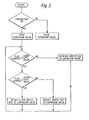
- the comparison device 25 contains preset limit values for the level of the liquid surface in the accumulator 23, and these values are used in controlling the opening and closing of the orifice of the expansion valve 21. Therefore, if the electronic expansion valve 21 is opened to a predetermined extent, the extent of opening is monitored by comparing the liquid level output from the sensor 24 with the preset limit values.
- the liquid level comparison device 25 When the liquid level in the accumulator 23 is less than or equal to the upper limit value, but equal to or greater than the lower limit value, the liquid level comparison device 25 does not generate a signal for altering the setting of the expansion valve 21. Accordingly, the electronic expansion valve 21 remains opened to its predetermined extent. That is, the orifice size of the electronic expansion valve 21 is fixed, and the refrigeration circuit operates as if it is a conventional accumulator refrigeration circuit with a fixed throttle valve.
- the comparison device 25 If the liquid level in the accumulator 23 exceeds the preset upper limit value, the comparison device 25 outputs a positive signal. When the control device 26 receives this positive signal, it reduces the orifice size of the electronic expansion valve 21. Otherwise, if the accumulator 23 is full of liquid refrigerant and the air conditioning load is reduced, liquid refrigerant might flow into the compressor 10. It is for this reason that it is necessary to throttle the orifice of the electronic expansion valve 21. The liquid level in the accumulator 23 drops once the orifice of the expansion valve 21 has been throttled. On the other hand, if the liquid level in the accumulator 23 drops below the preset lower limit value, the comparison device 25 outputs a negative signal.
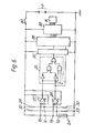
- the sensor 24 is connected to an electrical power source P via a switch 40.
- a voltage V s representative of the position of the float 242 of sensor 24 is supplied to inverting input terminals of comparators 27, 28.
- a reference voltage V l representative of the upper limit value for the liquid level is produced by a voltage divider formed by resistors 29, 30 and is supplied to a non-inverting terminal of the comparator 27.
- a reference voltage V 2 representative of the lower limit value for the liquid level is produced by a voltage divider formed by resistors 32, 33 and is supplied to a non-inverting input terminal of the comparator 28.
- the outputs of the comparator 27 and the comparator 28 are determined by the results of the comparisons of the reference voltages V 1 , V 2 with the voltage V s .
- reference voltage V I represents the upper limit value
- reference voltage V 2 represents lower limit value
- the reference voltage V 1 is always higher than the reference voltage V 2 .
- the comparators 27 and 28 are arranged so that when the voltage V s is higher than the reference voltage V 1 , the outputs of the two comparators 27, 28 are at high levels.
- the output of the comparator 27 drops to a low level whilst the outout of the comparator 28 remains at the high level.
- the outputs of the comparators 27, 28 are fed into a logic circuit 35.
- the output of the logic circuit 35 and the output of the comparator 28 are fed into a micro-computer 36 through an A-D converter 37 as control signals for the orifice of the electronic expansion valve 21.
- the output of the logic circuit 35 is at a high level.
- the output signals of the comparators are different to one another, i.e. when the voltage V S is higher than the reference voltage V 2 but lower than the reference voltage V 1 , the output of the logic circuit 35 is at a low level.
- the micro-computer 36 alters the orifice size of the electronic expansion valve 21 by means of a pulse motor M.
- the pulse motor M is driven by an output signal from a driving circuit 38 connected to the micro-computer 36.
- the micro-computer 36 does not instruct altering of the orifice size of the expansion valve 21.
- the driving circuit does not generate a signal to drive the pulse motor M.
- the micro-computer 36 includes a circuit for keeping the orifice of the expansion valve 21 opened to a predetermined extend for a predetermined period of time after the compressor 10 has been turned on.
Landscapes
- Engineering & Computer Science (AREA)
- Physics & Mathematics (AREA)
- Mechanical Engineering (AREA)
- Thermal Sciences (AREA)
- General Engineering & Computer Science (AREA)
- Automation & Control Theory (AREA)
- Power Engineering (AREA)
- Analytical Chemistry (AREA)
- Chemical & Material Sciences (AREA)
- General Physics & Mathematics (AREA)
- Air-Conditioning For Vehicles (AREA)
- Air Conditioning Control Device (AREA)
- Separation By Low-Temperature Treatments (AREA)
Applications Claiming Priority (2)
| Application Number | Priority Date | Filing Date | Title |
|---|---|---|---|
| JP206270/85 | 1985-09-20 | ||
| JP60206270A JPS6268115A (ja) | 1985-09-20 | 1985-09-20 | 自動車用空調装置の制御装置 |
Publications (2)
| Publication Number | Publication Date |
|---|---|
| EP0217605A2 true EP0217605A2 (fr) | 1987-04-08 |
| EP0217605A3 EP0217605A3 (fr) | 1987-09-09 |
Family
ID=16520546
Family Applications (1)
| Application Number | Title | Priority Date | Filing Date |
|---|---|---|---|
| EP86307225A Withdrawn EP0217605A3 (fr) | 1985-09-20 | 1986-09-19 | Système de conditionnement d'air |
Country Status (5)
| Country | Link |
|---|---|
| EP (1) | EP0217605A3 (fr) |
| JP (1) | JPS6268115A (fr) |
| KR (1) | KR870003355A (fr) |
| CN (1) | CN1004060B (fr) |
| AU (1) | AU589211B2 (fr) |
Cited By (10)
| Publication number | Priority date | Publication date | Assignee | Title |
|---|---|---|---|---|
| FR2645948A1 (fr) * | 1989-04-14 | 1990-10-19 | Mathieu Christian | Installation de recuperation d'un fluide frigorigene, notamment chlorofluorocarbone |
| EP0419857A3 (en) * | 1989-08-28 | 1991-08-14 | Linde Aktiengesellschaft | Method for monitoring a refrigeration plant |
| EP0592003A1 (fr) * | 1992-10-09 | 1994-04-13 | Kabushiki Kaisha Sankyo Seiki Seisakusho | Appareil comprenant un obturateur pour un réfrigérateur et un dispositif pour détecter l'arrêt de l'obturateur, et méthode d'utilisation de cet appareil |
| WO2001022013A1 (fr) * | 1999-09-08 | 2001-03-29 | Gram Equipment A/S | Refrigerateur dote d'un separateur de gaz liquide centrifuge |
| EP3438574A1 (fr) * | 2017-08-02 | 2019-02-06 | Wurm GmbH & Co. KG Elektronische Systeme | Installation frigorifique et procédé de réglage d'une installation frigorifique |
| CN113787883A (zh) * | 2021-09-07 | 2021-12-14 | 安徽江淮汽车集团股份有限公司 | 一种空调系统及车辆 |
| EP3601907B1 (fr) | 2017-03-28 | 2022-04-20 | Danfoss A/S | Système de compression de vapeur doté d'un séparateur de liquide de conduite d'aspiration |
| US11333449B2 (en) | 2018-10-15 | 2022-05-17 | Danfoss A/S | Heat exchanger plate with strengthened diagonal area |
| US11460230B2 (en) | 2015-10-20 | 2022-10-04 | Danfoss A/S | Method for controlling a vapour compression system with a variable receiver pressure setpoint |
| US12253279B1 (en) * | 2020-02-19 | 2025-03-18 | Advantek Consulting Engineering Inc. | Air conditioner with selectively activated coil segments for increased dehumidification and efficiency |
Families Citing this family (12)
| Publication number | Priority date | Publication date | Assignee | Title |
|---|---|---|---|---|
| JP4542414B2 (ja) | 2004-11-18 | 2010-09-15 | 株式会社豊田自動織機 | 水素燃料自動車における水素タンク冷却装置 |
| JP5399333B2 (ja) * | 2010-07-01 | 2014-01-29 | トヨタ自動車株式会社 | プレ空調システム |
| JP2012162125A (ja) * | 2011-02-04 | 2012-08-30 | Calsonic Kansei Corp | 冷凍サイクル装置 |
| CN103033005B (zh) * | 2011-09-29 | 2016-04-20 | 杭州三花研究院有限公司 | 一种汽车空调系统电子膨胀阀的控制方法 |
| CN103033008B (zh) * | 2011-09-29 | 2016-04-20 | 杭州三花研究院有限公司 | 一种汽车空调系统电子膨胀阀的控制方法 |
| US9829230B2 (en) * | 2013-02-28 | 2017-11-28 | Mitsubishi Electric Corporation | Air conditioning apparatus |
| JP7375486B2 (ja) * | 2018-12-14 | 2023-11-08 | 株式会社デンソー | 車両の熱交換システム |
| CN109878210B (zh) * | 2019-04-30 | 2020-10-16 | 漯河市慧光印刷科技有限公司 | 一种印刷机刮刀和回墨刀调节装置 |
| CN110530077A (zh) * | 2019-09-26 | 2019-12-03 | 珠海格力电器股份有限公司 | 可自动调节的冷媒量调节装置、方法及空调设备 |
| CN111237865B (zh) * | 2020-03-04 | 2022-04-12 | 青岛海信日立空调系统有限公司 | 一种多联式空调系统 |
| JP7007612B2 (ja) * | 2020-06-30 | 2022-01-24 | ダイキン工業株式会社 | 冷凍システムおよび熱源ユニット |
| CN112146314B (zh) * | 2020-09-22 | 2022-03-11 | 华商国际工程有限公司 | 氨泵供液制冷系统及其控制方法 |
Family Cites Families (13)
| Publication number | Priority date | Publication date | Assignee | Title |
|---|---|---|---|---|
| US129523A (en) * | 1872-07-16 | Improvement in magazine-guns | ||
| CA127409A (fr) * | 1910-01-07 | 1910-08-09 | Lyman Melvin Jones | Connexion de bielle |
| FR1073488A (fr) * | 1952-01-07 | 1954-09-27 | Trist & Co Ltd Ronald | Perfectionnements relatifs à un appareil pour contrôler le déplacement d'un élément par rapport au déplacement d'un autre élément |
| FR1057041A (fr) * | 1952-03-11 | 1954-03-04 | Merlin Gerin | Dispositif de contrôle et de commande automatique |
| US2694171A (en) * | 1953-01-26 | 1954-11-09 | Julian A Campbell | Electric motor system for liquid level control |
| US2799848A (en) * | 1953-12-17 | 1957-07-16 | Glantz Lester Murray | Two-level control system |
| US2858430A (en) * | 1954-02-08 | 1958-10-28 | Alco Valve Co | Electronic on-and-off control |
| US3461907A (en) * | 1966-08-18 | 1969-08-19 | Charles P Wood Jr | Liquid level control device for refrigeration systems |
| US3532956A (en) * | 1968-02-26 | 1970-10-06 | Steven I Simon | Automatic step reset controller |
| US3600904A (en) * | 1969-05-27 | 1971-08-24 | Emerson Electric Co | Control for refrigeration system |
| DE3066169D1 (en) * | 1980-04-18 | 1984-02-23 | Monseol Ltd | A compression refrigerator unit adjustable in accordance with the liquid flowing out from the evaporator |
| JPS57207773A (en) * | 1981-06-17 | 1982-12-20 | Taiheiyo Kogyo Kk | Method of controlling cooling circuit and its control valve |
| AU549713B2 (en) * | 1983-12-22 | 1986-02-06 | Carrier Corp. | Control of expansion valve in a refrigeration system |
-
1985
- 1985-09-20 JP JP60206270A patent/JPS6268115A/ja active Pending
-
1986
- 1986-09-19 EP EP86307225A patent/EP0217605A3/fr not_active Withdrawn
- 1986-09-19 AU AU62955/86A patent/AU589211B2/en not_active Ceased
- 1986-09-20 CN CN86106975.7A patent/CN1004060B/zh not_active Expired
- 1986-09-20 KR KR1019860007890A patent/KR870003355A/ko not_active Withdrawn
Cited By (14)
| Publication number | Priority date | Publication date | Assignee | Title |
|---|---|---|---|---|
| FR2645948A1 (fr) * | 1989-04-14 | 1990-10-19 | Mathieu Christian | Installation de recuperation d'un fluide frigorigene, notamment chlorofluorocarbone |
| EP0419857A3 (en) * | 1989-08-28 | 1991-08-14 | Linde Aktiengesellschaft | Method for monitoring a refrigeration plant |
| EP0592003A1 (fr) * | 1992-10-09 | 1994-04-13 | Kabushiki Kaisha Sankyo Seiki Seisakusho | Appareil comprenant un obturateur pour un réfrigérateur et un dispositif pour détecter l'arrêt de l'obturateur, et méthode d'utilisation de cet appareil |
| US5461294A (en) * | 1992-10-09 | 1995-10-24 | Kabushiki Kaisha Sankyo Seiki Seisakusho | Method of detecting the stop of a refrigerator damper, and device for practicing the method |
| US6666041B1 (en) | 1999-09-08 | 2003-12-23 | Gram Equipment A/S | Refrigerator with cyclone liquid gas separator |
| EA003381B1 (ru) * | 1999-09-08 | 2003-04-24 | Грэм Эквипмент А/С | Холодильная машина с циклонным сепаратором для разделения газа и жидкости |
| WO2001022013A1 (fr) * | 1999-09-08 | 2001-03-29 | Gram Equipment A/S | Refrigerateur dote d'un separateur de gaz liquide centrifuge |
| US11460230B2 (en) | 2015-10-20 | 2022-10-04 | Danfoss A/S | Method for controlling a vapour compression system with a variable receiver pressure setpoint |
| EP3601907B1 (fr) | 2017-03-28 | 2022-04-20 | Danfoss A/S | Système de compression de vapeur doté d'un séparateur de liquide de conduite d'aspiration |
| EP3438574A1 (fr) * | 2017-08-02 | 2019-02-06 | Wurm GmbH & Co. KG Elektronische Systeme | Installation frigorifique et procédé de réglage d'une installation frigorifique |
| DE102017117565A1 (de) * | 2017-08-02 | 2019-02-07 | Wurm Gmbh & Co. Kg Elektronische Systeme | Kälteanlage und verfahren zur regelung einer kälteanlage |
| US11333449B2 (en) | 2018-10-15 | 2022-05-17 | Danfoss A/S | Heat exchanger plate with strengthened diagonal area |
| US12253279B1 (en) * | 2020-02-19 | 2025-03-18 | Advantek Consulting Engineering Inc. | Air conditioner with selectively activated coil segments for increased dehumidification and efficiency |
| CN113787883A (zh) * | 2021-09-07 | 2021-12-14 | 安徽江淮汽车集团股份有限公司 | 一种空调系统及车辆 |
Also Published As
| Publication number | Publication date |
|---|---|
| KR870003355A (ko) | 1987-04-16 |
| JPS6268115A (ja) | 1987-03-28 |
| AU6295586A (en) | 1987-03-26 |
| CN1004060B (zh) | 1989-05-03 |
| EP0217605A3 (fr) | 1987-09-09 |
| AU589211B2 (en) | 1989-10-05 |
| CN86106975A (zh) | 1987-04-29 |
Similar Documents
| Publication | Publication Date | Title |
|---|---|---|
| EP0217605A2 (fr) | Système de conditionnement d'air | |
| EP0523902B1 (fr) | Système à circuit frigorifique | |
| EP0697087B1 (fr) | Commande du debit de refrigerant d'apres le niveau de liquide dans le separateur de phases d'un systeme de refrigeration a deux compresseurs et deux evaporateurs | |
| US5392612A (en) | Refrigeration system having a self adjusting control range | |
| EP0597597B1 (fr) | Dispositif de climatisation | |
| US5501267A (en) | Air conditioning apparatus for an electric vehicle using least power consumption between compressor and electric heater | |
| KR930004382B1 (ko) | 공기조화기 | |
| KR890004395B1 (ko) | 냉동 사이클 장치 | |
| US5655379A (en) | Refrigerant level control in a refrigeration system | |
| US5046325A (en) | Refrigerating circuit apparatus with two stage compressor and heat storage tank | |
| US6460359B1 (en) | Method and device for cool-drying | |
| US20010010158A1 (en) | Mobile air conditioning system and control mechanisms therefor | |
| US4507932A (en) | Control system for air conditioning systems | |
| EP0709630A1 (fr) | Système de refroidissement à compression de vapeur | |
| US4498311A (en) | Control device for a variable displacement compressor in an air conditioning system | |
| JP2008292112A (ja) | 冷凍サイクル装置のコンプレッサの吸入圧力推定装置 | |
| US5036697A (en) | Apparatus for detecting gas-liquid ratio of a fluid | |
| GB2130747A (en) | Control device for refrigeration cycle | |
| EP0351204A2 (fr) | Système de conditionnement d'air d'automobile avec dispositif de régulation | |
| IL44785A (en) | A refrigeration system provided with variable length capillary tube | |
| EP0085245B1 (fr) | Dispositif de réglage de capacité pour un compresseur dans un système de réfrigération | |
| KR960002567B1 (ko) | 냉동회로 | |
| JP2000205664A (ja) | 冷凍サイクル装置 | |
| JPH0510183Y2 (fr) | ||
| KR100230433B1 (ko) | 차량용 공기 조화 장치 |
Legal Events
| Date | Code | Title | Description |
|---|---|---|---|
| PUAI | Public reference made under article 153(3) epc to a published international application that has entered the european phase |
Free format text: ORIGINAL CODE: 0009012 |
|
| AK | Designated contracting states |
Kind code of ref document: A2 Designated state(s): DE FR GB IT SE |
|
| PUAL | Search report despatched |
Free format text: ORIGINAL CODE: 0009013 |
|
| AK | Designated contracting states |
Kind code of ref document: A3 Designated state(s): DE FR GB IT SE |
|
| 17P | Request for examination filed |
Effective date: 19880211 |
|
| 17Q | First examination report despatched |
Effective date: 19880926 |
|
| STAA | Information on the status of an ep patent application or granted ep patent |
Free format text: STATUS: THE APPLICATION IS DEEMED TO BE WITHDRAWN |
|
| 18D | Application deemed to be withdrawn |
Effective date: 19890207 |
|
| RIN1 | Information on inventor provided before grant (corrected) |
Inventor name: TAGUCHI, YUKIHIKO |