EP0217637A2 - Bande de calfatage extrudée - Google Patents
Bande de calfatage extrudée Download PDFInfo
- Publication number
- EP0217637A2 EP0217637A2 EP86307370A EP86307370A EP0217637A2 EP 0217637 A2 EP0217637 A2 EP 0217637A2 EP 86307370 A EP86307370 A EP 86307370A EP 86307370 A EP86307370 A EP 86307370A EP 0217637 A2 EP0217637 A2 EP 0217637A2
- Authority
- EP
- European Patent Office
- Prior art keywords
- strip
- caulk
- side edges
- tacky
- polymeric material
- Prior art date
- Legal status (The legal status is an assumption and is not a legal conclusion. Google has not performed a legal analysis and makes no representation as to the accuracy of the status listed.)
- Granted
Links
Images
Classifications
-
- B—PERFORMING OPERATIONS; TRANSPORTING
- B29—WORKING OF PLASTICS; WORKING OF SUBSTANCES IN A PLASTIC STATE IN GENERAL
- B29C—SHAPING OR JOINING OF PLASTICS; SHAPING OF MATERIAL IN A PLASTIC STATE, NOT OTHERWISE PROVIDED FOR; AFTER-TREATMENT OF THE SHAPED PRODUCTS, e.g. REPAIRING
- B29C48/00—Extrusion moulding, i.e. expressing the moulding material through a die or nozzle which imparts the desired form; Apparatus therefor
- B29C48/25—Component parts, details or accessories; Auxiliary operations
- B29C48/30—Extrusion nozzles or dies
- B29C48/305—Extrusion nozzles or dies having a wide opening, e.g. for forming sheets
- B29C48/307—Extrusion nozzles or dies having a wide opening, e.g. for forming sheets specially adapted for bringing together components, e.g. melts within the die
-
- B—PERFORMING OPERATIONS; TRANSPORTING
- B29—WORKING OF PLASTICS; WORKING OF SUBSTANCES IN A PLASTIC STATE IN GENERAL
- B29C—SHAPING OR JOINING OF PLASTICS; SHAPING OF MATERIAL IN A PLASTIC STATE, NOT OTHERWISE PROVIDED FOR; AFTER-TREATMENT OF THE SHAPED PRODUCTS, e.g. REPAIRING
- B29C48/00—Extrusion moulding, i.e. expressing the moulding material through a die or nozzle which imparts the desired form; Apparatus therefor
- B29C48/03—Extrusion moulding, i.e. expressing the moulding material through a die or nozzle which imparts the desired form; Apparatus therefor characterised by the shape of the extruded material at extrusion
- B29C48/12—Articles with an irregular circumference when viewed in cross-section, e.g. window profiles
-
- B—PERFORMING OPERATIONS; TRANSPORTING
- B29—WORKING OF PLASTICS; WORKING OF SUBSTANCES IN A PLASTIC STATE IN GENERAL
- B29C—SHAPING OR JOINING OF PLASTICS; SHAPING OF MATERIAL IN A PLASTIC STATE, NOT OTHERWISE PROVIDED FOR; AFTER-TREATMENT OF THE SHAPED PRODUCTS, e.g. REPAIRING
- B29C48/00—Extrusion moulding, i.e. expressing the moulding material through a die or nozzle which imparts the desired form; Apparatus therefor
- B29C48/16—Articles comprising two or more components, e.g. co-extruded layers
- B29C48/18—Articles comprising two or more components, e.g. co-extruded layers the components being layers
- B29C48/21—Articles comprising two or more components, e.g. co-extruded layers the components being layers the layers being joined at their surfaces
-
- B—PERFORMING OPERATIONS; TRANSPORTING
- B29—WORKING OF PLASTICS; WORKING OF SUBSTANCES IN A PLASTIC STATE IN GENERAL
- B29C—SHAPING OR JOINING OF PLASTICS; SHAPING OF MATERIAL IN A PLASTIC STATE, NOT OTHERWISE PROVIDED FOR; AFTER-TREATMENT OF THE SHAPED PRODUCTS, e.g. REPAIRING
- B29C48/00—Extrusion moulding, i.e. expressing the moulding material through a die or nozzle which imparts the desired form; Apparatus therefor
- B29C48/25—Component parts, details or accessories; Auxiliary operations
- B29C48/30—Extrusion nozzles or dies
-
- B—PERFORMING OPERATIONS; TRANSPORTING
- B29—WORKING OF PLASTICS; WORKING OF SUBSTANCES IN A PLASTIC STATE IN GENERAL
- B29C—SHAPING OR JOINING OF PLASTICS; SHAPING OF MATERIAL IN A PLASTIC STATE, NOT OTHERWISE PROVIDED FOR; AFTER-TREATMENT OF THE SHAPED PRODUCTS, e.g. REPAIRING
- B29C48/00—Extrusion moulding, i.e. expressing the moulding material through a die or nozzle which imparts the desired form; Apparatus therefor
- B29C48/25—Component parts, details or accessories; Auxiliary operations
- B29C48/30—Extrusion nozzles or dies
- B29C48/304—Extrusion nozzles or dies specially adapted for bringing together components, e.g. melts within the die
-
- B—PERFORMING OPERATIONS; TRANSPORTING
- B29—WORKING OF PLASTICS; WORKING OF SUBSTANCES IN A PLASTIC STATE IN GENERAL
- B29C—SHAPING OR JOINING OF PLASTICS; SHAPING OF MATERIAL IN A PLASTIC STATE, NOT OTHERWISE PROVIDED FOR; AFTER-TREATMENT OF THE SHAPED PRODUCTS, e.g. REPAIRING
- B29C48/00—Extrusion moulding, i.e. expressing the moulding material through a die or nozzle which imparts the desired form; Apparatus therefor
- B29C48/001—Combinations of extrusion moulding with other shaping operations
- B29C48/0018—Combinations of extrusion moulding with other shaping operations combined with shaping by orienting, stretching or shrinking, e.g. film blowing
-
- B—PERFORMING OPERATIONS; TRANSPORTING
- B29—WORKING OF PLASTICS; WORKING OF SUBSTANCES IN A PLASTIC STATE IN GENERAL
- B29C—SHAPING OR JOINING OF PLASTICS; SHAPING OF MATERIAL IN A PLASTIC STATE, NOT OTHERWISE PROVIDED FOR; AFTER-TREATMENT OF THE SHAPED PRODUCTS, e.g. REPAIRING
- B29C48/00—Extrusion moulding, i.e. expressing the moulding material through a die or nozzle which imparts the desired form; Apparatus therefor
- B29C48/03—Extrusion moulding, i.e. expressing the moulding material through a die or nozzle which imparts the desired form; Apparatus therefor characterised by the shape of the extruded material at extrusion
- B29C48/07—Flat, e.g. panels
-
- B—PERFORMING OPERATIONS; TRANSPORTING
- B29—WORKING OF PLASTICS; WORKING OF SUBSTANCES IN A PLASTIC STATE IN GENERAL
- B29C—SHAPING OR JOINING OF PLASTICS; SHAPING OF MATERIAL IN A PLASTIC STATE, NOT OTHERWISE PROVIDED FOR; AFTER-TREATMENT OF THE SHAPED PRODUCTS, e.g. REPAIRING
- B29C48/00—Extrusion moulding, i.e. expressing the moulding material through a die or nozzle which imparts the desired form; Apparatus therefor
- B29C48/03—Extrusion moulding, i.e. expressing the moulding material through a die or nozzle which imparts the desired form; Apparatus therefor characterised by the shape of the extruded material at extrusion
- B29C48/07—Flat, e.g. panels
- B29C48/08—Flat, e.g. panels flexible, e.g. films
-
- B—PERFORMING OPERATIONS; TRANSPORTING
- B29—WORKING OF PLASTICS; WORKING OF SUBSTANCES IN A PLASTIC STATE IN GENERAL
- B29L—INDEXING SCHEME ASSOCIATED WITH SUBCLASS B29C, RELATING TO PARTICULAR ARTICLES
- B29L2031/00—Other particular articles
- B29L2031/26—Sealing devices, e.g. packaging for pistons or pipe joints
- B29L2031/265—Packings, Gaskets
-
- Y—GENERAL TAGGING OF NEW TECHNOLOGICAL DEVELOPMENTS; GENERAL TAGGING OF CROSS-SECTIONAL TECHNOLOGIES SPANNING OVER SEVERAL SECTIONS OF THE IPC; TECHNICAL SUBJECTS COVERED BY FORMER USPC CROSS-REFERENCE ART COLLECTIONS [XRACs] AND DIGESTS
- Y10—TECHNICAL SUBJECTS COVERED BY FORMER USPC
- Y10T—TECHNICAL SUBJECTS COVERED BY FORMER US CLASSIFICATION
- Y10T428/00—Stock material or miscellaneous articles
- Y10T428/24—Structurally defined web or sheet [e.g., overall dimension, etc.]
- Y10T428/24752—Laterally noncoextensive components
-
- Y—GENERAL TAGGING OF NEW TECHNOLOGICAL DEVELOPMENTS; GENERAL TAGGING OF CROSS-SECTIONAL TECHNOLOGIES SPANNING OVER SEVERAL SECTIONS OF THE IPC; TECHNICAL SUBJECTS COVERED BY FORMER USPC CROSS-REFERENCE ART COLLECTIONS [XRACs] AND DIGESTS
- Y10—TECHNICAL SUBJECTS COVERED BY FORMER USPC
- Y10T—TECHNICAL SUBJECTS COVERED BY FORMER US CLASSIFICATION
- Y10T428/00—Stock material or miscellaneous articles
- Y10T428/28—Web or sheet containing structurally defined element or component and having an adhesive outermost layer
-
- Y—GENERAL TAGGING OF NEW TECHNOLOGICAL DEVELOPMENTS; GENERAL TAGGING OF CROSS-SECTIONAL TECHNOLOGIES SPANNING OVER SEVERAL SECTIONS OF THE IPC; TECHNICAL SUBJECTS COVERED BY FORMER USPC CROSS-REFERENCE ART COLLECTIONS [XRACs] AND DIGESTS
- Y10—TECHNICAL SUBJECTS COVERED BY FORMER USPC
- Y10T—TECHNICAL SUBJECTS COVERED BY FORMER US CLASSIFICATION
- Y10T428/00—Stock material or miscellaneous articles
- Y10T428/28—Web or sheet containing structurally defined element or component and having an adhesive outermost layer
- Y10T428/2852—Adhesive compositions
-
- Y—GENERAL TAGGING OF NEW TECHNOLOGICAL DEVELOPMENTS; GENERAL TAGGING OF CROSS-SECTIONAL TECHNOLOGIES SPANNING OVER SEVERAL SECTIONS OF THE IPC; TECHNICAL SUBJECTS COVERED BY FORMER USPC CROSS-REFERENCE ART COLLECTIONS [XRACs] AND DIGESTS
- Y10—TECHNICAL SUBJECTS COVERED BY FORMER USPC
- Y10T—TECHNICAL SUBJECTS COVERED BY FORMER US CLASSIFICATION
- Y10T428/00—Stock material or miscellaneous articles
- Y10T428/28—Web or sheet containing structurally defined element or component and having an adhesive outermost layer
- Y10T428/2852—Adhesive compositions
- Y10T428/2878—Adhesive compositions including addition polymer from unsaturated monomer
- Y10T428/2891—Adhesive compositions including addition polymer from unsaturated monomer including addition polymer from alpha-beta unsaturated carboxylic acid [e.g., acrylic acid, methacrylic acid, etc.] Or derivative thereof
Definitions
- the present invention relates to a pre-formed caulk strip and to a method of making the same by utilizing an extrusion process.
- Caulking has been used in the building trades for both utilitarian and aesthetic reasons to cover open spaces, gaps or cracks between or within various structural members. Caulking is often used between metal panels, over expansion joints, around perimeters of door frames and window frames, between adjacent concrete slabs, and between a concrete slab and a foundation.
- caulking material as a sealant around a sink, bath tub or shower stall and its adjacent structural elements such as a wall or floor (which may be covered with ceramic or plastic tile) has been known for some time.
- Such caulking materials are used to prevent infiltration of water and water borne salts into cracks and to otherwise seal the cracks to prevent water damage and provide a more aesthetic appearance. Without a proper seal, water generally seeps into the crack, typically under the influence of capillary action, penetrates the underlying structure such as plaster, sheet rock, or wood, thereby causing crumbling of plaster or sheet rock, rotting, mildewing or molding of wood, and staining of adjacent surfaces such as the wall or ceiling below. This necessitates expensive repairs.
- caulking material has a rubber base which is plasticized, filled and tackified to provide a deformable plastic mass which generally has immediate adhesion for the surfaces upon which it is applied. Some caulks will cure to a non-tacky state while others retain their applied physical properties. The curing time for certain curable caulking materials to achieve a tack-free surface is often long, causing an accumulation of dust particles on its surface, which can result in an unsightly appearance.
- Caulking materials are typically applied in a variety of ways. Some caulking materials come in a cartridge which is placed into a caulking gun which forces the caulking material out of a small opening, about the diameter of a pencil, for deposit on the crack or seam. Other caulking materials are available in a putty-like composition for application by an appropriate tool. Still others are available in elongate strips which can merely be deposited appropriately.
- caulking materials make it difficult to apply a uniform fillet or bead of such material by the unskilled, often resulting in smearing, gaps or other defects. Additionally, the long curing time results in accumulation of dirt, dust, and other particles and leaves the uncured caulk susceptible to damage caused by inadvertent subsequent contact.
- U.S. Pat. No. 3,556,926 discloses the preparation of a caulking tape which attempts to meet this need by heating an oil-wax and polymer mixture and rapidly cooling one surface of the tape to cause such surface to be less tacky, but the resultant tacky surface of the composition would not be as effective a caulk as conventional rubber-based caulking materials because of the wax content which would make it less adherent.
- a commercial product comprising a tacky caulk fillet or bead adherently bonded to the surface of a dimensionalized (e.g., by biaxial orientation and heat setting) polyester film is available under the trade designation "Press-n-Seal" from Consumer Products Management Group, Inc. of P.0. Box 12886 Shawnee Mission, Kansas.
- Such a product is difficult to make because it requires deposition of the caulk fillet on a ribbon of the film, making placement of the fillet with respect to the film side edges difficult to control, necessitating the leaving of a large exposed film edge on each side of the fillet.
- the present invention provides an extruded caulking strip which is simple to apply to seal cracks or seams to provide an aesthetic appearance.
- the extruded caulk strip of the present invention comprises a substantially amorphous, non-tacky, conformable, elongate protective strip and a self-supporting, elongated, deformable, continuous, tacky caulk body.
- the protective strip has opposed major surfaces and opposed side edges and is formed of thermoplastic, film-forming polymeric material.
- the caulk body is in melt fusion contact with one major surface of the protective strip.
- the caulk body extends the entire length of the protective strip and has side edges within the side edges of the protective strip, with no more than about 1 mm, preferably 0.5 mm, most preferably 0.2 mm of the strip surface being exposed on either side of the caulk body.
- the preferred caulk body has a transverse cross section which is a trapezoid.
- amorphous refers to the fact that the extruded thermoplastic material forming the protective strip according to the invention has a relatively low amount of crystallinity, making it much more conformable and ductile.
- dimensionalized polymeric film such as biaxially oriented, heat-set polyethylene terephthalate, is highly crystalline and not so conformable or ductile.
- the caulk strip of the present invention is made by a method which comprises the steps of
- the process described above involves coextrusion, i.e., the forming of a composite article of thermoplastic material by simultaneously extruding each constituent element of the composite structure through a separate extrusion opening so that the extruded parts meet while in a semi-molten or plastic tacky state sufficient to cause intermingling of the constituents at the interface whereby they become firmly united on cooling.
- coextrusion i.e., the forming of a composite article of thermoplastic material by simultaneously extruding each constituent element of the composite structure through a separate extrusion opening so that the extruded parts meet while in a semi-molten or plastic tacky state sufficient to cause intermingling of the constituents at the interface whereby they become firmly united on cooling.
- the article of the present invention could be produced because the polymeric material forming the protective strip of the extruded caulk strip has vastly different thermoplastic properties than those of the caulking material.
- the caulking material typically cannot be heated much beyond about 100°C in order to maintain its structural integrity and shape.
- Suitable thermoplastic materials which are candidates for the protective strip are extrudable only at much higher temperatures, typically in excess of about 160°C, leading one to believe that such a composite caulk strip could not be made by coextrusion.
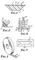
- FIGs. 1 and 3 there is shown an extruded caulk strip 10 having a protective strip 11 and a caulk body 12.
- Caulk 10 is conveniently carried on a release liner 13 which has sufficient adhesion for the surface of caulk body 12 and, on its backside, preferably a modest degree of frictional engagement with the exposed surface 15 of protective strip 11 so that a roll of strip 10 on a release liner 13 will not uncoil as the side of the roll is held parallel to the ground by its outer edge.
- a preferred release liner having these properties is formed of a polyethylene-paper-polyethylene laminate with one polyethylene surface coated with a silicone release material. A commercial embodiment of this material is available from Akrosil Division of Thilmay Paper Corp., Menasha, Wisconsin.
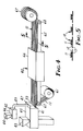
- Apparatus 40 includes two conventional extruders 41 and 42, each of which has a hopper 43 and 44, respectively, for receiving polymer, typically in the form of chips and pellets, and a housing 45 and 46, respectively, each of which includes a heating and mixing chamber for converting solid thermoplastic material into a plastic extrudable form and a means for pumping the plastic extrudable material to an extrusion die 47.
- Extrusion die 47 is shown in more detail in FIG. 6 as having a channel 48 for the passage of plastic extrudable material from extruder 42.
- a stream 50 of plastic extrudable material from extruder 41 passes from extrusion orifice 51 to form shaped caulk body 52.
- the part of the extrusion die block which permits the passage and shaping of the material forming the protective strip is thermally isolated from the part of the extrusion die block which permits the passage and shaping of the caulk mass.
- thermal isolation may be accomplished by the placement therebetween of a non-heat-conductive barrier 70, e.g., formed of ceramic material, glass fibers or the like.
- Extrusion opening 51 is shown in greater detail in FIG. 7 as having inwardly curving side dimensions 53 and inwardly curving bottom dimensions 54 rather than straight dimensions as would be expected in the formation of a trapazoidal shape from an extruded mass.
- the inwardly curving dimensions are required because of the visco-elastic properties of the caulk extrudate.
- the viscosity of the extruded caulk is such that it causes "die swell", i.e., expansion as it exits the die, thereby distorting its side dimensions.
- the die opening of the type depicted in FIG. 7 is therefor necessary to achieve a desired trapazoidal shape.
- the plastic material pumped from extruder 42 passes through conduit 49 through connecting passages 55 and 56 and out of slit-like opening 57 to form a strip 58 which merges with shaped caulk body 52 while the two are sufficiently tacky and adherent to form a self-fusion bond therebetween. Simultaneous extrusion of several extrudates may be accomplished as shown in FIG. 4 which reveals the simultaneous extrusion of four extrudates, as further depicted in cross section in FIG. 5.
- Release liner 13 from storage roll 61 is fed onto belt 62 which is carried on idler rolls 63 and 64 to receive composite extrudate 59 which is then cooled, either by utilizing a cooling station 66 which impinges an air blast on extrudate strips 10 or by merely having a sufficient length to permit cooling between the extrusion die and a take up roll 67 for caulk strip 10.
- the cross-sectional shape of caulk body 12 can take any variety of forms, the preferred being trapazoidal as shown. Other suitable forms include cross sections which are rectangular (e.g., square), hemispherical, triangular, and the like. Additionally, face 17 of strip 10 opposite protective strip 11 need not be flat or outwardly curving, but it could also be indented or otherwise shaped.
- the cross sectional dimensions may very, according to the particular utility contemplated. That is, where larger gaps are to be sealed, the dimensions would be correspondingly larger.
- the preferred dimensions are in the range of 1 to 5 mm in thickness and from 5 to 20 mm in average width, i.e., the dimension midway between the two parallel sides of the trapazoid.
- the protective strip preferably is relatively thin, e.g., on the order of about 0.1 to about 1 mm, when compared to the thickness of a caulk body.
- the protective strip preferably has a flat exposed surface 15 and a flat surface 16 which interfaces with the surface of caulk body 12, although surface 16 may take any shape so long as the material forming protective strip 11 does not interfere with the performance of the caulk.
- the material forming caulk body 12 can be any conventional caulking compound which is extrudable and which will maintain conventional caulking properties after melt extrusion as described above.
- the preferred caulking materials are those having a rubbery base, i.e., include a substantial portion of rubber such as butyl, polysulfide, polychloroprene, room temperature vulcanizable (RTV) silicone or acrylic rubber. Such rubbery materials may be in the latex form.
- caulking materials are typically compounded to a putty-like consistency with fillers such as calcium carbonate, zinc oxide, silica, tackifiers such as polybutene oils or terpene resins, plasticizers such as polybutene oils, thixotropes such as clays or colloidal silicas, and antioxidants.
- fillers such as calcium carbonate, zinc oxide, silica, tackifiers such as polybutene oils or terpene resins, plasticizers such as polybutene oils, thixotropes such as clays or colloidal silicas, and antioxidants.
- fillers such as calcium carbonate, zinc oxide, silica, tackifiers such as polybutene oils or terpene resins, plasticizers such as polybutene oils, thixotropes such as clays or colloidal silicas, and antioxidants.
- tackifiers such as polybutene oils or terpene resins
- plasticizers such as polybut
- a preferred useful caulking compound which hardens by solvent evaporation is as follows:
- a preferred caulking composition is composed of emulsions and solutions of poly(methylmethacrylate) or its copolymers.
- a typical useful caulking composition based upon acrylic latex is as follows:
- caulking compositions which are useful in the practice of this invention are as follows:
- the material forming the protective strip can be any thermoplastic film-forming polymeric material which, on extrusion and cooling, forms a substantially amorphous, non-tacky conformable strip.
- Preferred film-forming polymeric materials include thermoplastic polyurethanes, polyolefins (e.g, polyethylene, polypropylene, etc.), polyvinyl resins and the like.
- the preferred film-forming polymeric material is a thermoplastic polyurethane.
- the film-forming material may include additives normally found in plastics which are used in such situations such as, for example, anti-microbial agents, UV stabilizers, coloring agents, agents to modify the surface texture, and the like.
- caulking compound A The ingredients of caulking compound A were combined and mixed on a high shear mixer for a period of from 1-1/2 to 4 hours and then formed into suitable billets for extrusion.
- the thermoplastic film-forming polymeric material (in Protective strip Composition) was fed in pellet form into hopper 44 and thence through extruder 42 with a temperature gradient from about 179°C to an exit temperature of about 200°C.
- the two materials were extruded simultaneously onto a release liner 13 and thence into the cooling station 66.
- the resultant caulking strip performed well as a bathroom caulk, but tended to disintegrate on subsequent exposure to high acid cleaning materials.
- caulking compound B The ingredients of caulking compound B were combined and mixed on a high shear mixer for a period of from 1-1/2 to 4 hours and then formed into suitable billets for extrusion.
- the thermoplastic film-forming polymeric material (in Protective Strip Composition) was fed in pellet form into hopper 44 and thence through extruder 42 with a temperature gradient from about 179°C to an exit temperature of about 200°C.
- the two materials were extruded simultaneously onto a release liner 13 and thence into the cooling station 66.
- the resultant caulk strip performed well as a bathroom caulk with no detrimental affect when exposed to acid type cleaning materials.
Landscapes
- Engineering & Computer Science (AREA)
- Mechanical Engineering (AREA)
- Manufacturing & Machinery (AREA)
- Laminated Bodies (AREA)
- Sealing Material Composition (AREA)
- Building Environments (AREA)
- Door And Window Frames Mounted To Openings (AREA)
- Extrusion Moulding Of Plastics Or The Like (AREA)
Applications Claiming Priority (2)
| Application Number | Priority Date | Filing Date | Title |
|---|---|---|---|
| US06/782,359 US4629648A (en) | 1985-10-01 | 1985-10-01 | Extruded caulk strip |
| US782359 | 1991-10-24 |
Publications (3)
| Publication Number | Publication Date |
|---|---|
| EP0217637A2 true EP0217637A2 (fr) | 1987-04-08 |
| EP0217637A3 EP0217637A3 (en) | 1988-12-07 |
| EP0217637B1 EP0217637B1 (fr) | 1991-11-06 |
Family
ID=25125806
Family Applications (1)
| Application Number | Title | Priority Date | Filing Date |
|---|---|---|---|
| EP86307370A Expired - Lifetime EP0217637B1 (fr) | 1985-10-01 | 1986-09-25 | Bande de calfatage extrudée |
Country Status (6)
| Country | Link |
|---|---|
| US (1) | US4629648A (fr) |
| EP (1) | EP0217637B1 (fr) |
| JP (1) | JPH07103362B2 (fr) |
| CA (1) | CA1283519C (fr) |
| DE (1) | DE3682359D1 (fr) |
| ZA (1) | ZA867085B (fr) |
Cited By (1)
| Publication number | Priority date | Publication date | Assignee | Title |
|---|---|---|---|---|
| DE102018120852A1 (de) * | 2018-08-27 | 2020-02-27 | Bayer Vitrotechnic Gmbh | Vorrichtung und Verfahren zur Herstellung von Dichtungsbändern |
Families Citing this family (19)
| Publication number | Priority date | Publication date | Assignee | Title |
|---|---|---|---|---|
| US4822655A (en) * | 1986-08-08 | 1989-04-18 | Beecham Home Improvements Products Inc. | Butyl rubber preformed tape sealant |
| IT1224303B (it) * | 1988-11-09 | 1990-10-04 | Siv Soc Italiana Vetro | Procedimento e dispositivo per la fabbricazione di una guarnizione sul bordo di una lastra di vetro |
| US5397521A (en) * | 1992-07-01 | 1995-03-14 | Quinn; Pam | Method for fabricating a dimensionalized configuration |
| US5364677A (en) * | 1993-02-03 | 1994-11-15 | Gexco Ent. A Division Of Tennis Ball Saver, Inc. | Self-adhesive wrap-on grip for sports racquets and other equipment handles |
| US5635274A (en) * | 1994-06-21 | 1997-06-03 | Gencorp Inc. | Molded glass run channel composite |
| US5730446A (en) * | 1995-06-20 | 1998-03-24 | Minnesota Mining And Manufacturing Company | Sealing strip suitable for sealing a hem flange |
| US5569696A (en) * | 1995-07-13 | 1996-10-29 | The W. W. Henry Company | Stain resistant grout |
| US6907696B1 (en) | 2002-06-05 | 2005-06-21 | Allan Hutton | Caulk application device |
| ITGE20020061A1 (it) * | 2002-07-05 | 2004-01-05 | Ali Spa | Metodo per la formazione di elementi integrati di guarnizione su manufatti di plastica mediante sovrastampaggio con pellicole siliconiche. |
| US20070298272A1 (en) * | 2004-07-08 | 2007-12-27 | Nhk Spring Co., Ltd. | Gasket, Method For Producing The Gasket, And Gasket Installation Method |
| WO2006127649A2 (fr) * | 2005-05-22 | 2006-11-30 | U.S. Borax Inc. | Formulation co-biocide pour materiaux polymeres |
| US7434812B2 (en) * | 2005-11-23 | 2008-10-14 | Hercules Chemical Company Incorporated | Putty composition and method |
| WO2008101191A2 (fr) * | 2007-02-16 | 2008-08-21 | W.R. Grace & Co.-Conn. | Matériau étanche à fixation mécanique et à adhérence provisoire |
| US9457547B2 (en) * | 2007-11-07 | 2016-10-04 | Magnum Magnetics Corporation | Extrudable adherable material systems |
| US9783999B2 (en) * | 2009-07-27 | 2017-10-10 | Gregory A Amundson | Flexible corner trim product |
| CA2900614C (fr) | 2013-03-15 | 2021-10-26 | Oatey Co. | Ensemble clapet de non-retour et procede |
| US9765960B2 (en) | 2015-08-31 | 2017-09-19 | Gregory A. Amundson | Inside corner trim product |
| US10294715B1 (en) * | 2018-01-02 | 2019-05-21 | Diana L. Hertel | Methods of forming a temporary seal for flood protection |
| US10895104B1 (en) | 2020-02-11 | 2021-01-19 | Diana L. Hertel | Device for forming a temporary seal for flood protection |
Family Cites Families (15)
| Publication number | Priority date | Publication date | Assignee | Title |
|---|---|---|---|---|
| US2256864A (en) * | 1940-05-11 | 1941-09-23 | William C Ferguson | Sealing composition |
| US2454821A (en) * | 1944-02-02 | 1948-11-30 | Nat Greenhouse Co | Glazing and caulking material |
| US2541768A (en) * | 1948-07-03 | 1951-02-13 | Kenneth M Keller | Flexible molding strip |
| US3332055A (en) * | 1962-03-08 | 1967-07-18 | K & W Products Inc | Adhesive coating and calking composition |
| US3556926A (en) * | 1968-04-02 | 1971-01-19 | Chevron Res | Shock-cooled caulking tape and method of preparation |
| GB1251146A (fr) * | 1969-04-23 | 1971-10-27 | ||
| CA985341A (en) * | 1972-03-20 | 1976-03-09 | Alex Kunevicius | Molding and method and means of making the same |
| DE2246679C3 (de) * | 1972-09-22 | 1980-11-13 | Dynamit Nobel Ag, 5210 Troisdorf | Vorrichtung zum Extrudieren eines aus thermoplastischen Kunststoffen bestehenden Strangprofils mit einem Kernprofil und einer Deckschicht |
| CH565031A5 (fr) * | 1972-09-22 | 1975-08-15 | Dynamit Nobel Ag | |
| US4109431A (en) * | 1974-03-25 | 1978-08-29 | Ppg Industries, Inc. | Sealing and spacing unit for multiple glazed windows |
| FR2275707A1 (fr) * | 1974-06-20 | 1976-01-16 | Silvatrim Sa | Profile couvre-joint a garniture etanche et adhesive |
| JPS57165469A (en) * | 1981-04-07 | 1982-10-12 | Toa Nenryo Kogyo Kk | Adhesive resin composition and its laminate |
| GB2097710A (en) * | 1981-05-01 | 1982-11-10 | Silvatrim Ass | Padded molding strip |
| US4536445A (en) * | 1981-12-28 | 1985-08-20 | Raychem Corporation | Elastomer based adhesive compositions |
| IE821334L (en) * | 1982-06-03 | 1983-12-03 | Inst Ind Res And Standards S 2 | Window facing member |
-
1985
- 1985-10-01 US US06/782,359 patent/US4629648A/en not_active Expired - Lifetime
-
1986
- 1986-09-17 ZA ZA867085A patent/ZA867085B/xx unknown
- 1986-09-18 CA CA000518467A patent/CA1283519C/fr not_active Expired - Lifetime
- 1986-09-25 DE DE8686307370T patent/DE3682359D1/de not_active Expired - Lifetime
- 1986-09-25 EP EP86307370A patent/EP0217637B1/fr not_active Expired - Lifetime
- 1986-09-30 JP JP61233110A patent/JPH07103362B2/ja not_active Expired - Lifetime
Cited By (1)
| Publication number | Priority date | Publication date | Assignee | Title |
|---|---|---|---|---|
| DE102018120852A1 (de) * | 2018-08-27 | 2020-02-27 | Bayer Vitrotechnic Gmbh | Vorrichtung und Verfahren zur Herstellung von Dichtungsbändern |
Also Published As
| Publication number | Publication date |
|---|---|
| JPH07103362B2 (ja) | 1995-11-08 |
| JPS62124179A (ja) | 1987-06-05 |
| EP0217637B1 (fr) | 1991-11-06 |
| ZA867085B (en) | 1988-04-27 |
| DE3682359D1 (de) | 1991-12-12 |
| CA1283519C (fr) | 1991-04-30 |
| US4629648A (en) | 1986-12-16 |
| EP0217637A3 (en) | 1988-12-07 |
Similar Documents
| Publication | Publication Date | Title |
|---|---|---|
| EP0217637B1 (fr) | Bande de calfatage extrudée | |
| US4364886A (en) | Process for the manufacture of polyvinylidene fluoride - incompatible polymer laminates | |
| US5580630A (en) | Multi-layer waterproofing articles including a layer of water-soluble polymer | |
| AU2002359520B2 (en) | Caulkless panelized wall system | |
| US5599602A (en) | Double-sided pressure-sensitive adhesive tape and method of making | |
| US20050257875A1 (en) | Process for coating modified bitumen membranes using reflective laminate coatings | |
| JPH09501879A (ja) | 賦形品並びにその製造方法およびダイ | |
| EP1697477B1 (fr) | Bande d'etancheite pour coller des feuilles pare-vapeur, ainsi que procedes pour sa production | |
| US20060260213A1 (en) | Pan flashing with sill wedge | |
| EP0734425A1 (fr) | Ruban auto-adhesif double face et son procede de fabrication | |
| EP0293074A2 (fr) | Mélange de polymères pour film, pellicule ou laminé d'emballage | |
| US7841146B2 (en) | Product and method for concealing joints | |
| CA1064781A (fr) | Methode de laminage a chaud et produit final | |
| US20050081476A1 (en) | Drywall-trimming accessory and methods for making same and/or preparing same to adhere to drywall-finishing compound | |
| EP1009632B1 (fr) | Procede de production de plaques multicouches profilees, installation associee et plaques multicouches profilees ainsi produites | |
| US3842551A (en) | Drywall joint systems and method for making the same | |
| CN1176360A (zh) | 一种型材及其框架 | |
| US5934034A (en) | Foundation material for use with putty and manufacturing method therefor | |
| CN114133165B (zh) | 一种防辐射墙板配方及其生产装置 | |
| CN109577604B (zh) | 一种石墨eps板及制作工艺及其应用于楼地面的铺设方法 | |
| DE1962640A1 (de) | Bautenschutzfolie | |
| US20070254151A1 (en) | System for concealing joints | |
| EP3330470B1 (fr) | Ruban d'étanchéité avec agencement de couche adhésive | |
| JP2574017B2 (ja) | フツ素樹脂系フイルム被覆発泡積層体 | |
| JP2963466B2 (ja) | フッ素樹脂系フィルム被覆セメント成形物の製造方法およびその製造用部材 |
Legal Events
| Date | Code | Title | Description |
|---|---|---|---|
| PUAI | Public reference made under article 153(3) epc to a published international application that has entered the european phase |
Free format text: ORIGINAL CODE: 0009012 |
|
| AK | Designated contracting states |
Kind code of ref document: A2 Designated state(s): DE FR GB IT NL SE |
|
| PUAL | Search report despatched |
Free format text: ORIGINAL CODE: 0009013 |
|
| AK | Designated contracting states |
Kind code of ref document: A3 Designated state(s): DE FR GB IT NL SE |
|
| 17P | Request for examination filed |
Effective date: 19890321 |
|
| 17Q | First examination report despatched |
Effective date: 19900108 |
|
| GRAA | (expected) grant |
Free format text: ORIGINAL CODE: 0009210 |
|
| ITF | It: translation for a ep patent filed | ||
| AK | Designated contracting states |
Kind code of ref document: B1 Designated state(s): DE FR GB IT NL SE |
|
| REF | Corresponds to: |
Ref document number: 3682359 Country of ref document: DE Date of ref document: 19911212 |
|
| ET | Fr: translation filed | ||
| PLBE | No opposition filed within time limit |
Free format text: ORIGINAL CODE: 0009261 |
|
| STAA | Information on the status of an ep patent application or granted ep patent |
Free format text: STATUS: NO OPPOSITION FILED WITHIN TIME LIMIT |
|
| 26N | No opposition filed | ||
| EAL | Se: european patent in force in sweden |
Ref document number: 86307370.6 |
|
| PGFP | Annual fee paid to national office [announced via postgrant information from national office to epo] |
Ref country code: SE Payment date: 19990902 Year of fee payment: 14 |
|
| PGFP | Annual fee paid to national office [announced via postgrant information from national office to epo] |
Ref country code: NL Payment date: 19990908 Year of fee payment: 14 |
|
| PG25 | Lapsed in a contracting state [announced via postgrant information from national office to epo] |
Ref country code: SE Free format text: THE PATENT HAS BEEN ANNULLED BY A DECISION OF A NATIONAL AUTHORITY Effective date: 20000929 |
|
| PG25 | Lapsed in a contracting state [announced via postgrant information from national office to epo] |
Ref country code: NL Free format text: LAPSE BECAUSE OF NON-PAYMENT OF DUE FEES Effective date: 20010401 |
|
| EUG | Se: european patent has lapsed |
Ref document number: 86307370.6 |
|
| NLV4 | Nl: lapsed or anulled due to non-payment of the annual fee |
Effective date: 20010401 |
|
| PGFP | Annual fee paid to national office [announced via postgrant information from national office to epo] |
Ref country code: FR Payment date: 20010831 Year of fee payment: 16 Ref country code: DE Payment date: 20010831 Year of fee payment: 16 |
|
| PGFP | Annual fee paid to national office [announced via postgrant information from national office to epo] |
Ref country code: GB Payment date: 20010904 Year of fee payment: 16 |
|
| REG | Reference to a national code |
Ref country code: GB Ref legal event code: IF02 |
|
| PG25 | Lapsed in a contracting state [announced via postgrant information from national office to epo] |
Ref country code: GB Free format text: LAPSE BECAUSE OF NON-PAYMENT OF DUE FEES Effective date: 20020925 |
|
| PG25 | Lapsed in a contracting state [announced via postgrant information from national office to epo] |
Ref country code: DE Free format text: LAPSE BECAUSE OF NON-PAYMENT OF DUE FEES Effective date: 20030401 |
|
| GBPC | Gb: european patent ceased through non-payment of renewal fee |
Effective date: 20020925 |
|
| PG25 | Lapsed in a contracting state [announced via postgrant information from national office to epo] |
Ref country code: FR Free format text: LAPSE BECAUSE OF NON-PAYMENT OF DUE FEES Effective date: 20030603 |
|
| REG | Reference to a national code |
Ref country code: FR Ref legal event code: ST |
|
| PG25 | Lapsed in a contracting state [announced via postgrant information from national office to epo] |
Ref country code: IT Free format text: LAPSE BECAUSE OF NON-PAYMENT OF DUE FEES Effective date: 20050925 |