EP0217721A1 - Grille de protection à déverrouillage en cas de panique - Google Patents
Grille de protection à déverrouillage en cas de panique Download PDFInfo
- Publication number
- EP0217721A1 EP0217721A1 EP86450018A EP86450018A EP0217721A1 EP 0217721 A1 EP0217721 A1 EP 0217721A1 EP 86450018 A EP86450018 A EP 86450018A EP 86450018 A EP86450018 A EP 86450018A EP 0217721 A1 EP0217721 A1 EP 0217721A1
- Authority
- EP
- European Patent Office
- Prior art keywords
- panel
- panels
- closed position
- protective grid
- adjacent
- Prior art date
- Legal status (The legal status is an assumption and is not a legal conclusion. Google has not performed a legal analysis and makes no representation as to the accuracy of the status listed.)
- Granted
Links
- 230000004888 barrier function Effects 0.000 title 1
- 230000001681 protective effect Effects 0.000 claims abstract description 9
- XEEYBQQBJWHFJM-UHFFFAOYSA-N Iron Chemical compound [Fe] XEEYBQQBJWHFJM-UHFFFAOYSA-N 0.000 description 2
- 239000011521 glass Substances 0.000 description 1
- 229910052742 iron Inorganic materials 0.000 description 1
- 229910052751 metal Inorganic materials 0.000 description 1
- 238000000926 separation method Methods 0.000 description 1
Images

Classifications
-
- E—FIXED CONSTRUCTIONS
- E06—DOORS, WINDOWS, SHUTTERS, OR ROLLER BLINDS IN GENERAL; LADDERS
- E06B—FIXED OR MOVABLE CLOSURES FOR OPENINGS IN BUILDINGS, VEHICLES, FENCES OR LIKE ENCLOSURES IN GENERAL, e.g. DOORS, WINDOWS, BLINDS, GATES
- E06B11/00—Means for allowing passage through fences, barriers or the like, e.g. stiles
- E06B11/02—Gates; Doors
-
- E—FIXED CONSTRUCTIONS
- E05—LOCKS; KEYS; WINDOW OR DOOR FITTINGS; SAFES
- E05B—LOCKS; ACCESSORIES THEREFOR; HANDCUFFS
- E05B65/00—Locks or fastenings for special use
- E05B65/10—Locks or fastenings for special use for panic or emergency doors
Definitions
- the present invention relates to an automatic and simultaneous unlocking device for protective grids located for example in public places to ensure effective separation between the public and the performance area.
- the present invention makes it possible to carry out this operation on command by triggering remotely the unlocking of all or part of these grids.
- the subject of the invention is a protective grid with automatic unlocking in the event of panic, comprising at least one group of individual panels each disposed between two consecutive poles of a series of aligned poles, characterized in that each panel is articulated around an axis carried by one of the adjacent posts and carries, in line with the articulation post, hooking and locking means in the closed position of the adjacent panel, capable of being retracted and of releasing said panel adjacent when the carrier panel of said means is rotated and in that one of the end panels of said group is lockable in the closed position by a remote control device.
- Said hooking and locking means are, for example, constituted, on the one hand, by a projecting member in the form of a hook or the like, integral with the vertical upright of one of two adjacent panels and, on the other hand, by a retaining member of said projecting member, integral with the vertical upright of the other panel, being in the immediate vicinity of the first upright, in the closed position of said panels, said members unlocking after a rotation of a determined amplitude of l one and / or the other of the panels from their closed position.
- each panel comprises a means, such as a helical spring housed in the articulation post, exerting permanently on the panel, in the closed position of the latter, a force tending to open the panel.
- a means such as a helical spring housed in the articulation post, exerting permanently on the panel, in the closed position of the latter, a force tending to open the panel.
- Such a device allows, by a simple remote control of the unlocking of said end panel of the or each group, to release all the panels which can open, either by themselves under the action of the opening spring, either under the sole thrust of the spectators in the absence of such springs.
- Figures 1 and 2 show a grid consisting of a group of individual panels B, C, D each arranged between two vertical posts 1 fixed in the ground and aligned to form a continuous fence.
- each panel is a mesh panel consisting of galvanized rectangular metallic elements provided with vertical tubular uprights 2 and 3 ( Figure 5) superimposed on the right of each post 1, in the closed position.
- Panel A is an end panel and can be replaced by a fixed wall or completely removed.
- Panel A comprises a vertical upright 2 welded to a post 1 constituted by an I-shaped iron sealed in the ground.
- the bolt 5 is controlled by a remotely controlled coil 6.
- a spring 7 recalls the bolt 5 in the locking position of the panel B.
- a handle 8 optionally makes it possible to control the bolt 5 manually.
- the handle 8 can be padlocked with a station key in a box with breaking glass.
- Each panel B, C, D of the grid is articulated on one of the posts 1 and can pivot around an axis coincident or not with that of said post.
- each panel B, C, D has a vertical upright 2 welded to a tube 9 mounted journalled in a sheath 10 sealed in the ground and constituting (with the tube 9) said post 1.
- the Figure 4 shows the lower part of the tube 9 and the two adjacent panels B and C, the sheath 10 protruding very slightly from the ground surface.
- a projecting member 11 in the form of a hook capable of cooperating with the upright 3 of the panel C in the closed position (FIG. 5) of the latter.
- said upright 3 is provided with an orifice 12 into which the hook 11 can penetrate so as to retain the panel C closed when the panel B is itself in the closed position.
- unlocking the first panel B can therefore allow people massed on the side of the panels opposite the panel release area to push the panels effortlessly and open them to quickly cross the gate thus opened on the all of its individual panels.
- the opening of the passage if necessary is therefore total and instantaneous.
- a means tending to open each panel and constituted for example by a coil spring 14 housed in the tube 9 and fixed, on the one hand, on the latter and, on the other hand, on the fixed sleeve 10.
- the spring 14 constantly exerts on the panel a force tending to open the latter. Consequently, as soon as the first panel B is unlocked, the latter automatically opens to a certain degree under the action of its spring 14. In doing so, it releases the panel immediately following C which also opens itself and thus immediately to the last panel of the group constituting the grid.
- the entire grid is in position at least partially open over its entire length, from the opening of the bolt 5 and even before the crowd has reached the panels B, C, D, etc.
- the maximum opening angle of the panels can be limited to approximately 90 ° by providing, for example, a stud 15 arranged on the internal face of a flange 16 secured to the tube 9 and covering the upper edge of the sheath 10 in partial overflow.
- the stud 15 moves in a notch 17 formed in said upper edge of the sheath 10 and is capable of abutting, when the opening angle of the panel is close to 90 °, with one of the ends of the notch 17. Any other means of limiting the opening angle can of course be used, as well as any other means than the spring 14, to urge each panel B, C, D, etc., to open continuously.
- electrically controlled locks such as 4 can be provided on the same first panel of the group constituting the grid. It can also be made up of several distinct sections, each consisting of several panels and controlled by electric locks 4.
- the panels B, C, D etc ... can have any structure and shape.
Landscapes
- Engineering & Computer Science (AREA)
- Civil Engineering (AREA)
- Structural Engineering (AREA)
- Refuge Islands, Traffic Blockers, Or Guard Fence (AREA)
- Housing For Livestock And Birds (AREA)
- Bedding Items (AREA)
- Pinball Game Machines (AREA)
- Machines For Laying And Maintaining Railways (AREA)
- Chutes (AREA)
- Operating, Guiding And Securing Of Roll- Type Closing Members (AREA)
- Air Filters, Heat-Exchange Apparatuses, And Housings Of Air-Conditioning Units (AREA)
- Fencing (AREA)
- Gates (AREA)
- Baking, Grill, Roasting (AREA)
- Other Air-Conditioning Systems (AREA)
- Cookers (AREA)
- Measurement Of The Respiration, Hearing Ability, Form, And Blood Characteristics Of Living Organisms (AREA)
- Soil Working Implements (AREA)
Abstract
Description
- La présente invention concerne un dispositif de déverrouillage automatique et simultané pour des grilles de protection situées par exemple dans des lieux publics permettant d'assurer la séparation efficace entre le public et l'aire de spectacle.
- Jusqu'à présent l'ensemble de ces grilles sont fixes et si la protection est ainsi efficace, les risques d'entassement et d'écrasement contre ces grilles sont grands lorsqu'il se passe un évènement dramatique qui engendre la panique dans la foule, (effondrement des tribunes, incendies, bagarres).Dans ces cas extrêmes, le seul endroit hors de danger c'est justement l'aire d'évolution et, en toute logique, c'est donc vers cet emplacement qu'il faut évacuer le public le plus rapidement possible en ouvrant ces grilles.
- La présente invention permet de réaliser sur commande cette opération en déclenchant à distance le déverrouillage de tout ou partie de ces grilles.
- A cet effet, l'invention a pour objet une grille de protection à déverrouillage automatique en cas de panique, comprenant au moins un groupe de panneaux individuels disposés chacun entre deux poteaux consécutifs d'une série de poteaux alignés, caractérisée en ce que chaque panneau est articulé autour d'un axe porté par l'un des poteaux adjacents et porte, au droit du poteau d'articulation, des moyens d'accrochage et verrouillage en position fermée du panneau adjacent, susceptibles de s'escamoter et de libérer ledit panneau adjacent lors de la rotation du panneau porteur desdits moyens et en ce que l'un des panneaux d'extrémité dudit groupe est verrouillable en position fermée par un dispositif à commande à distance.
- Lesdits moyens d'accrochage et verrouillage sont, par exemple, constitués, d'une part, par un organe en saillie en forme de crochet ou analogue, solidaire du montant vertical de l'un de deux panneaux adjacents et, d'autre part, par un organe de retenue dudit organe en saillie, solidaire du montant vertical de l'autre panneau, se trouvant à proximité immédiate du premier montant, en position de fermeture desdits panneaux, lesdits organes se déverrouillant après une rotation d'une amplitude déterminée de l'un et/ou de l'autre des panneaux à partir de leur position de fermeture.
- Avantageusement, chaque panneau comporte un moyen, tel qu'un ressort hélicoïdal logé dans le poteau d'articulation, exerçant en permanence sur le panneau, en position de fermeture de ce dernier, un effort tendant à ouvrir le panneau.
- Un tel dispositif permet par une simple commande à distance du déverrouillage dudit panneau d'extrémité du ou de chaque groupe, de libérer tous les panneaux qui peuvent s'ouvrir, soit d'eux-mêmes sous l'action du ressort d'ouverture, soit sous la seule poussée des spectateurs en l'absence de tels ressorts.
- D'autres caractéristiques et avantages ressortiront de la description qui va suivre d'un mode de réalisation du dispositif de l'invention, description donnée à titre d'exemple uniquement et en regard des dessins annexés sur lesquels :
- - Figure 1 représente une vue en élévation d'une grille conforme à l'invention;
- - Figure 2 est une vue de dessus de la grille de la figure 1;
- - Figure 3 est une vue agrandie de la partie cerclée en III de la figure 2
- - Figure 4 est une vue en élévation agrandie et partielle de la partie inférieure du poteau interposé entre les panneaux B et C de la grille de la figure 1, et
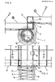
- - Figure 5 est une vue de dessus en coupe suivant la ligne V-V du dispositif de la figure 4.
- Les figures 1 et 2 représentent une grille constituée par un groupe de panneaux individuels B,C,D disposés chacun entre deux poteaux verticaux 1 fixés dans le sol et alignés pour former une clôture continue.
- Dans le mode de réalisation représenté chaque panneau est un panneau grillagé constitué d'éléments métalliques galvanisés rectangulaires pourvus de montants verticaux tubulaires 2 et 3 (figure 5) venant se superposer au droit de chaque poteau 1, en position de fermeture.
- Le panneau A est un panneau d'extrémité et peut être remplacé par une paroi fixe ou carrément supprimé.
- Le panneau A comporte un montant vertical 2 soudé à un poteau 1 constitué par un fer en I scellé dans le sol.
- Contre le montant 2 vient s'appliquer en position de fermeture du premier panneau B de la grille, le montant 3 de ce panneau B.
- Le verrouillage entre les panneaux A et B est assuré par un verrou à commande électrique 4 fixé sur le panneau A et dont le pène 5 pénètre dans un orifice approprié ménagé dans le montant 3 dudit premier panneau B de la grille selon l'invention.
- La commande du pène 5 est assurée par une bobine 6 commandée à distance. Un ressort 7 rappelle le pène 5 en position de verrouillage du panneau B.
- Une poignée 8 permet éventuellement de commander le pène 5 manuellement. La poignée 8 peut être cadenassée avec clef à poste dans une boîte avec vitre à briser.
- Chaque panneau B,C,D de la grille est articulé sur l'un des poteaux 1 et peut pivoter autour d'un axe confondu ou non avec celui dudit poteau.
- Dans le mode de réalisation des figures 4 et 5 chaque panneau B,C,D comporte un montant vertical 2 soudé à un tube 9 monté tourillonnant dans un fourreau 10 scellé dans le sol et constituant (avec le tube 9) ledit poteau 1. La figure 4 représente la partie inférieure du tube 9 et des deux panneaux adjacents B et C, le fourreau 10 dépassant très légèrement de la surface du sol.
- Les poteaux symbolisés en 1 sur la figure 1 et définissant les axes d'articulation des panneaux individuels B,C, D, etc... peuvent bien entendu avoir une toute autre structure sans que l'on sorte pour autant du cadre de l'invention.
- Sur le montant 2 du panneau B est fixé un organe en saillie 11 en forme de crochet susceptible de coopérer avec le montant 3 du panneau C en position de fermeture (figure 5) de ce dernier. A cet effet, ledit montant 3 est muni d'un orifice 12 dans lequel peut pénétrer le crochet 11 de manière à retenir le panneau C fermé lorsque le panneau B est lui-même en position de fermeture.
- Lorsque tous les panneaux B,C,D etc... de la grille sont dans la position illustrée par la figure 5 et que le premier panneau B est verrouillé par le pène 5, tous les panneaux de la grille se verrouillent mutuellement.
- Dès que le retrait du pène 5 est commandé, le premier panneau de la grille B est libéré et peut s'ouvrir en pivotant autour de son poteau 1 comme indiqué par la flèche 13 sur les dessins. En considérant la figure 5 on comprend aisément que la rotation du panneau B autour de l'axe de l'ensemble 9-10 permet au crochet 11 d'échapper à l'orifice 12 et de libérer le panneau C qui peut ainsi s'ouvrir suivant la flèche 13 en pivotant autour de son propre poteau 1 d'articulation. Il en est de même de tous les autres panneaux successifs (D,etc...) qui comportent tous bien entendu le même dispositif que celui représenté sur la figure 5.
- En cas d'urgence, le déverrouillage du premier panneau B peut donc permettre à des personnes massées du côté des panneaux opposés à la zone de dégagement des panneaux, de pousser ces derniers sans effort et les ouvrir pour franchir rapidement la grille ainsi ouverte sur la totalité de ses panneaux individuels.
- L'ouverture du passage en cas de nécessité est donc totale et instantanée.
- Pour faciliter encore le libre passage, on peut prévoir, comme représenté sur les figures 4 et 5, un moyen tendant à ouvrir chaque panneau et constitué par exemple par un ressort hélicoïdal 14 logé dans le tube 9 et fixé, d'une part, sur ce dernier et, d'autre part, sur le fourreau fixe 10. Le ressort 14 exerce constamment sur le panneau un effort tendant à ouvrir ce dernier. Par suite, dès le déverrouillage du premier panneau B, ce dernier s'ouvre automatiquement d'un certain degré sous l'action de son ressort 14. Ce faisant, il libère le panneau immédiatement suivant C qui s'ouvre lui-aussi et ainsi de suite jusqu'au dernier panneau du groupe constituant la grille.
- Ainsi la totalité de la grille est en position au moins partiellement ouverte sur toute sa longueur, dès l'ouverture du pène 5 et avant même que la foule ait atteint les panneaux B,C,D, etc...
- L'angle maximal d'ouverture des panneaux peut être limité à 90° environ en prévoyant par exemple un téton 15 disposé sur la face interne d'une collerette 16 solidaire du tube 9 et recouvrant en débordement partiel le rebord supérieur du fourreau 10.
- Le téton 15 se déplace dans une encoche 17 ménagée dans ledit rebord supérieur du fourreau 10 et est susceptible de venir en butée, lorsque l'angle d'ouverture du panneau avoisine 90°, avec l'une des extrémités de l'encoche 17. Tout autre moyen de limitation de l'angle d'ouverture peut bien entendu être utilisé, de même que tout autre moyen que le ressort 14, pour solliciter en permancence à l'ouverture chaque panneau B,C,D etc...
- Plusieurs verrous à commande électrique à distance tels que 4 peuvent être prévus sur le même premier panneau du groupe constituant la grille. Celle-ci peut aussi être formée de plusieurs tronçons distincts chacun constitué de plusieurs panneaux et commandé par des verrous électriques 4.
- Enfin, les panneaux B,C,D etc... peuvent avoir une structure et une forme quelconques.
Claims (6)
Priority Applications (1)
| Application Number | Priority Date | Filing Date | Title |
|---|---|---|---|
| AT86450018T ATE48462T1 (de) | 1985-09-06 | 1986-09-03 | Schutzzaun mit entriegelung im fall einer panik. |
Applications Claiming Priority (2)
| Application Number | Priority Date | Filing Date | Title |
|---|---|---|---|
| FR8513433 | 1985-09-06 | ||
| FR8513433A FR2587057B1 (fr) | 1985-09-06 | 1985-09-06 | Grille de protection a deverrouillage automatique en cas de panique |
Publications (2)
| Publication Number | Publication Date |
|---|---|
| EP0217721A1 true EP0217721A1 (fr) | 1987-04-08 |
| EP0217721B1 EP0217721B1 (fr) | 1989-12-06 |
Family
ID=9322781
Family Applications (1)
| Application Number | Title | Priority Date | Filing Date |
|---|---|---|---|
| EP86450018A Expired EP0217721B1 (fr) | 1985-09-06 | 1986-09-03 | Grille de protection à déverrouillage en cas de panique |
Country Status (10)
| Country | Link |
|---|---|
| EP (1) | EP0217721B1 (fr) |
| AT (1) | ATE48462T1 (fr) |
| DE (1) | DE3667315D1 (fr) |
| ES (1) | ES2004159A6 (fr) |
| FR (1) | FR2587057B1 (fr) |
| GR (1) | GR862267B (fr) |
| MA (1) | MA20763A1 (fr) |
| OA (1) | OA08392A (fr) |
| PT (1) | PT83304B (fr) |
| TN (1) | TNSN86125A1 (fr) |
Cited By (6)
| Publication number | Priority date | Publication date | Assignee | Title |
|---|---|---|---|---|
| DE3736251A1 (de) * | 1987-10-27 | 1989-05-11 | Hans Lechtenboehmer | Einseitig zu oeffnendes tor |
| GB2231066A (en) * | 1989-05-05 | 1990-11-07 | Stuart Morris | Safety fence |
| GB2239272A (en) * | 1989-11-11 | 1991-06-26 | Soltrepac Ltd | Crowd control barrier |
| GB2242210A (en) * | 1990-03-23 | 1991-09-25 | Derek Anthony Lake | Safety barrier |
| EP0437341A3 (en) * | 1990-01-10 | 1992-09-02 | Nnc Limited | Barrier structures |
| GB2639063A (en) * | 2024-08-16 | 2025-09-10 | Andres Vilas Lorenzo Alejandro | A sports field barrier device |
Families Citing this family (1)
| Publication number | Priority date | Publication date | Assignee | Title |
|---|---|---|---|---|
| NL2002521C2 (nl) * | 2009-02-12 | 2010-08-16 | Andries Cornelis Moree | Hek met afzonderlijke sluitinrichting. |
Citations (6)
| Publication number | Priority date | Publication date | Assignee | Title |
|---|---|---|---|---|
| US1430382A (en) * | 1921-06-15 | 1922-09-26 | Johnson Otto | Fence |
| US1540490A (en) * | 1924-02-07 | 1925-06-02 | Summit Brass & Bronze Works In | Gate mounting |
| GB603401A (en) * | 1945-10-19 | 1948-06-15 | Leslie Gordon Forster | Improvements in or relating to hinged gates |
| GB940107A (en) * | 1961-05-03 | 1963-10-23 | Commissariat Energie Atomique | Improvements in adjustable partitions |
| DE1801990A1 (de) * | 1968-10-09 | 1970-06-04 | Lamour Rolf Heinz | Kassen- und Kartenabrissanlage mit Absperrung |
| US4083535A (en) * | 1976-10-28 | 1978-04-11 | Britt James O | Portable fence |
-
1985
- 1985-09-06 FR FR8513433A patent/FR2587057B1/fr not_active Expired
-
1986
- 1986-09-03 DE DE8686450018T patent/DE3667315D1/de not_active Expired - Lifetime
- 1986-09-03 EP EP86450018A patent/EP0217721B1/fr not_active Expired
- 1986-09-03 PT PT83304A patent/PT83304B/pt not_active IP Right Cessation
- 1986-09-03 AT AT86450018T patent/ATE48462T1/de not_active IP Right Cessation
- 1986-09-04 GR GR862267A patent/GR862267B/el unknown
- 1986-09-04 TN TNTNSN86125A patent/TNSN86125A1/fr unknown
- 1986-09-05 OA OA58947A patent/OA08392A/fr unknown
- 1986-09-05 MA MA20991A patent/MA20763A1/fr unknown
- 1986-09-05 ES ES8601999A patent/ES2004159A6/es not_active Expired - Lifetime
Patent Citations (6)
| Publication number | Priority date | Publication date | Assignee | Title |
|---|---|---|---|---|
| US1430382A (en) * | 1921-06-15 | 1922-09-26 | Johnson Otto | Fence |
| US1540490A (en) * | 1924-02-07 | 1925-06-02 | Summit Brass & Bronze Works In | Gate mounting |
| GB603401A (en) * | 1945-10-19 | 1948-06-15 | Leslie Gordon Forster | Improvements in or relating to hinged gates |
| GB940107A (en) * | 1961-05-03 | 1963-10-23 | Commissariat Energie Atomique | Improvements in adjustable partitions |
| DE1801990A1 (de) * | 1968-10-09 | 1970-06-04 | Lamour Rolf Heinz | Kassen- und Kartenabrissanlage mit Absperrung |
| US4083535A (en) * | 1976-10-28 | 1978-04-11 | Britt James O | Portable fence |
Cited By (7)
| Publication number | Priority date | Publication date | Assignee | Title |
|---|---|---|---|---|
| DE3736251A1 (de) * | 1987-10-27 | 1989-05-11 | Hans Lechtenboehmer | Einseitig zu oeffnendes tor |
| GB2231066A (en) * | 1989-05-05 | 1990-11-07 | Stuart Morris | Safety fence |
| GB2239272A (en) * | 1989-11-11 | 1991-06-26 | Soltrepac Ltd | Crowd control barrier |
| EP0437341A3 (en) * | 1990-01-10 | 1992-09-02 | Nnc Limited | Barrier structures |
| GB2242210A (en) * | 1990-03-23 | 1991-09-25 | Derek Anthony Lake | Safety barrier |
| GB2242210B (en) * | 1990-03-23 | 1994-06-29 | Derek Anthony Lake | Safety barriers |
| GB2639063A (en) * | 2024-08-16 | 2025-09-10 | Andres Vilas Lorenzo Alejandro | A sports field barrier device |
Also Published As
| Publication number | Publication date |
|---|---|
| FR2587057B1 (fr) | 1987-12-04 |
| PT83304A (fr) | 1986-10-01 |
| MA20763A1 (fr) | 1987-04-01 |
| OA08392A (fr) | 1988-02-29 |
| ATE48462T1 (de) | 1989-12-15 |
| TNSN86125A1 (fr) | 1990-01-01 |
| GR862267B (en) | 1987-01-02 |
| EP0217721B1 (fr) | 1989-12-06 |
| PT83304B (pt) | 1991-02-08 |
| DE3667315D1 (de) | 1990-01-11 |
| FR2587057A1 (fr) | 1987-03-13 |
| ES2004159A6 (es) | 1991-01-01 |
Similar Documents
| Publication | Publication Date | Title |
|---|---|---|
| EP0151076B1 (fr) | Dispositif pour condamner l'accès aux échelles à crinoline | |
| CH631230A5 (fr) | Dispositif de fermeture de securite a plusieurs lames pour batiments. | |
| EP0179960B1 (fr) | Coffre à ouverture assistée pour la protection d'un appareillage se présentant sous la forme d'un poteau | |
| EP0081417A1 (fr) | Enceinte de sûreté comportant un ou plusieurs compartiments verticaux | |
| EP0217721B1 (fr) | Grille de protection à déverrouillage en cas de panique | |
| BE1007921A3 (fr) | Dispositif pour le coffrage de plafond. | |
| EP2686489B1 (fr) | Ensemble a cadre de support et grille de securite antichute | |
| EP0267343A1 (fr) | Dispositif de protection contre des véhicules piégés ou à intrusion intempestive | |
| EP0314565B1 (fr) | Dispositif de condamnation de l'accès supérieur d'un conduit tubulaire vertical | |
| FR2635357A1 (fr) | Dispositif de condamnation de l'acces inferieur d'une echelle | |
| EP0485489B1 (fr) | Echelle a dispositif anti-chute et a condamnation d'acces | |
| EP1334236A1 (fr) | Barriere extensible sur roulettes a elements modulaires pivotants deployable et repliable manuellement | |
| EP0270437B1 (fr) | Dispositif de condamnation de porte | |
| EP0517612B1 (fr) | Dispositif de manoeuvre d'au moins un volet notamment d'une fenêtre d'habitation | |
| FR2836946A1 (fr) | Dispositif de double verrouillage, notamment pour portillon ou analogue de barriere de protection d'une piscine | |
| FR2696499A1 (fr) | Dispositif destiné à la fermeture d'une ouverture pratiquée dans le mur d'un local protégé contre l'incendie. | |
| EP0329535B1 (fr) | Barrière-écluse basculante de sécurité pour plate-forme | |
| FR2578803A1 (fr) | Parc a bicyclettes modulaire formant abri antivol d'encombrement reduit. | |
| FR2728012A1 (fr) | Dispositif pour limiter l'acces inferieur a une echelle a crinoline | |
| FR2716916A1 (fr) | Dispositif de verrouillage de fenêtre ou de porte. | |
| FR2601062A1 (fr) | Loquet de verrouillage a pene pivotant, destine notamment a une partie comportant une fermeture antipanique. | |
| FR2520432A1 (fr) | Dispositif de verrouillage automatique du tablier deploye d'un volet roulant | |
| FR2654125A1 (fr) | Borne de stationnement rabattable. | |
| WO1990015219A1 (fr) | Dispositif de protection de l'acces a une echelle a partir d'un plancher superieur | |
| EP1914349A1 (fr) | Dispositifs et ensemble de fermeture temporaire d'un passage piétonnier tel qu'un couloir |
Legal Events
| Date | Code | Title | Description |
|---|---|---|---|
| PUAI | Public reference made under article 153(3) epc to a published international application that has entered the european phase |
Free format text: ORIGINAL CODE: 0009012 |
|
| AK | Designated contracting states |
Kind code of ref document: A1 Designated state(s): AT BE CH DE GB IT LI LU NL SE |
|
| 17P | Request for examination filed |
Effective date: 19870923 |
|
| 17Q | First examination report despatched |
Effective date: 19880819 |
|
| GRAA | (expected) grant |
Free format text: ORIGINAL CODE: 0009210 |
|
| AK | Designated contracting states |
Kind code of ref document: B1 Designated state(s): AT BE CH DE GB IT LI LU NL SE |
|
| REF | Corresponds to: |
Ref document number: 48462 Country of ref document: AT Date of ref document: 19891215 Kind code of ref document: T |
|
| REF | Corresponds to: |
Ref document number: 3667315 Country of ref document: DE Date of ref document: 19900111 |
|
| ITF | It: translation for a ep patent filed | ||
| GBT | Gb: translation of ep patent filed (gb section 77(6)(a)/1977) | ||
| PLBE | No opposition filed within time limit |
Free format text: ORIGINAL CODE: 0009261 |
|
| STAA | Information on the status of an ep patent application or granted ep patent |
Free format text: STATUS: NO OPPOSITION FILED WITHIN TIME LIMIT |
|
| 26N | No opposition filed | ||
| REG | Reference to a national code |
Ref country code: CH Ref legal event code: PUE Owner name: PLASTIL |
|
| NLS | Nl: assignments of ep-patents |
Owner name: SOCIETE PLASTIL TE MOUTHIERS, FRANKRIJK. |
|
| EPTA | Lu: last paid annual fee | ||
| ITTA | It: last paid annual fee | ||
| EAL | Se: european patent in force in sweden |
Ref document number: 86450018.6 |
|
| PGFP | Annual fee paid to national office [announced via postgrant information from national office to epo] |
Ref country code: BE Payment date: 19990817 Year of fee payment: 14 |
|
| PGFP | Annual fee paid to national office [announced via postgrant information from national office to epo] |
Ref country code: AT Payment date: 19990819 Year of fee payment: 14 |
|
| PGFP | Annual fee paid to national office [announced via postgrant information from national office to epo] |
Ref country code: GB Payment date: 19990825 Year of fee payment: 14 |
|
| PGFP | Annual fee paid to national office [announced via postgrant information from national office to epo] |
Ref country code: SE Payment date: 19990916 Year of fee payment: 14 |
|
| PGFP | Annual fee paid to national office [announced via postgrant information from national office to epo] |
Ref country code: LU Payment date: 19990922 Year of fee payment: 14 |
|
| PGFP | Annual fee paid to national office [announced via postgrant information from national office to epo] |
Ref country code: NL Payment date: 19990928 Year of fee payment: 14 |
|
| PGFP | Annual fee paid to national office [announced via postgrant information from national office to epo] |
Ref country code: DE Payment date: 19991115 Year of fee payment: 14 |
|
| PGFP | Annual fee paid to national office [announced via postgrant information from national office to epo] |
Ref country code: CH Payment date: 19991202 Year of fee payment: 14 |
|
| PG25 | Lapsed in a contracting state [announced via postgrant information from national office to epo] |
Ref country code: LU Free format text: LAPSE BECAUSE OF NON-PAYMENT OF DUE FEES Effective date: 20000903 Ref country code: GB Free format text: LAPSE BECAUSE OF NON-PAYMENT OF DUE FEES Effective date: 20000903 Ref country code: AT Free format text: LAPSE BECAUSE OF NON-PAYMENT OF DUE FEES Effective date: 20000903 |
|
| PG25 | Lapsed in a contracting state [announced via postgrant information from national office to epo] |
Ref country code: SE Free format text: THE PATENT HAS BEEN ANNULLED BY A DECISION OF A NATIONAL AUTHORITY Effective date: 20000929 |
|
| PG25 | Lapsed in a contracting state [announced via postgrant information from national office to epo] |
Ref country code: LI Free format text: LAPSE BECAUSE OF NON-PAYMENT OF DUE FEES Effective date: 20000930 Ref country code: CH Free format text: LAPSE BECAUSE OF NON-PAYMENT OF DUE FEES Effective date: 20000930 Ref country code: BE Free format text: LAPSE BECAUSE OF NON-PAYMENT OF DUE FEES Effective date: 20000930 |
|
| BERE | Be: lapsed |
Owner name: PLASTIL Effective date: 20000930 |
|
| PG25 | Lapsed in a contracting state [announced via postgrant information from national office to epo] |
Ref country code: NL Free format text: LAPSE BECAUSE OF NON-PAYMENT OF DUE FEES Effective date: 20010401 |
|
| GBPC | Gb: european patent ceased through non-payment of renewal fee |
Effective date: 20000903 |
|
| REG | Reference to a national code |
Ref country code: CH Ref legal event code: PL |
|
| EUG | Se: european patent has lapsed |
Ref document number: 86450018.6 |
|
| NLV4 | Nl: lapsed or anulled due to non-payment of the annual fee |
Effective date: 20010401 |
|
| PG25 | Lapsed in a contracting state [announced via postgrant information from national office to epo] |
Ref country code: DE Free format text: LAPSE BECAUSE OF NON-PAYMENT OF DUE FEES Effective date: 20010601 |
|
| PG25 | Lapsed in a contracting state [announced via postgrant information from national office to epo] |
Ref country code: IT Free format text: LAPSE BECAUSE OF NON-PAYMENT OF DUE FEES;WARNING: LAPSES OF ITALIAN PATENTS WITH EFFECTIVE DATE BEFORE 2007 MAY HAVE OCCURRED AT ANY TIME BEFORE 2007. THE CORRECT EFFECTIVE DATE MAY BE DIFFERENT FROM THE ONE RECORDED. Effective date: 20050903 |