EP0218094B1 - Gerät zum Aufzeichnen und Wiedergeben von Strahlungsbildern - Google Patents
Gerät zum Aufzeichnen und Wiedergeben von Strahlungsbildern Download PDFInfo
- Publication number
- EP0218094B1 EP0218094B1 EP86112174A EP86112174A EP0218094B1 EP 0218094 B1 EP0218094 B1 EP 0218094B1 EP 86112174 A EP86112174 A EP 86112174A EP 86112174 A EP86112174 A EP 86112174A EP 0218094 B1 EP0218094 B1 EP 0218094B1
- Authority
- EP
- European Patent Office
- Prior art keywords
- image
- stimulable phosphor
- image recording
- scanning
- section
- Prior art date
- Legal status (The legal status is an assumption and is not a legal conclusion. Google has not performed a legal analysis and makes no representation as to the accuracy of the status listed.)
- Expired
Links
Images

Classifications
-
- G—PHYSICS
- G03—PHOTOGRAPHY; CINEMATOGRAPHY; ANALOGOUS TECHNIQUES USING WAVES OTHER THAN OPTICAL WAVES; ELECTROGRAPHY; HOLOGRAPHY
- G03B—APPARATUS OR ARRANGEMENTS FOR TAKING PHOTOGRAPHS OR FOR PROJECTING OR VIEWING THEM; APPARATUS OR ARRANGEMENTS EMPLOYING ANALOGOUS TECHNIQUES USING WAVES OTHER THAN OPTICAL WAVES; ACCESSORIES THEREFOR
- G03B42/00—Obtaining records using waves other than optical waves; Visualisation of such records by using optical means
- G03B42/02—Obtaining records using waves other than optical waves; Visualisation of such records by using optical means using X-rays
Definitions
- This invention relates to a radiation image recording and read-out apparatus provided with:
- This invention particularly relates to a radiation image recording and read-out apparatus in which the stimulable phosphor sheets are circulated and reused for recording radiation images.
- phosphors When certain kinds of phosphors are exposed to a radiation such as X-rays, ⁇ -rays, ⁇ -rays, ⁇ -rays, cathode rays or ultraviolet rays, they store a part of the energy of the radiation. Then, when the phosphor which has been exposed to the radiation is exposed to stimulating rays such as visible light, light is emitted by the phosphor in proportion to the stored energy of the radiation. A phosphor exhibiting such properties is referred to as a stimulable phosphor.
- a stimulable phosphor sheet As disclosed in U.S. Patent No. 4,258,264, 4,276,473, 4,315,318 and 4,387,428 and Japanese Unexamined Patent Publication No. 56(1981)-11395, it has been proposed to use a stimulable phosphor in a radiation image recording and reproducing system. Specifically, a sheet comprising the stimulable phosphor (hereinafter referred to as a stimulable phosphor sheet or simply as a sheet) is first exposed to a radiation passing through an object to have a radiation image stored thereon, and is then scanned with stimulating rays which cause it to emit light in proportion to the radiation energy stored.
- a stimulable phosphor sheet As disclosed in U.S. Patent No. 4,258,264, 4,276,473, 4,315,318 and 4,387,428 and Japanese Unexamined Patent Publication No. 56(1981)-11395, it has been proposed to use a stimulable phosphor in a radiation image recording and reproducing system. Specifically,
- the light emitted by the stimulable phosphor sheet when the sheet is exposed to the stimulating rays is photoelectrically detected and converted into an electric image signal, which is processed as desired to reproduce a visible image having an improved image quality, particularly a high diagnostic efficiency and accuracy.
- the finally obtained visible image may be reproduced in the form of a hard copy or may be displayed on a cathode ray tube (CRT).
- the stimulable phosphor sheet is used to temporarily store the radiation image in order to reproduce the final visible image therefrom on a final recording medium. For economical reasons, therefore, it is desirable that the stimulable phosphor sheet be used repeatedly.
- a mobile X-ray diagnostic station such as a traveling X-ray diagnostic station in the form of a vehicle like a bus which is provided with a radiation image recording and read-out apparatus for use in the aforesaid radiation image recording and reproducing system and moves from place to place to record radiation images for mass medical examinations
- the mobile X-ray diagnostic station with stimulable phosphor sheets which can be used repeatedly, once store the radiation images of the objects respectively on the stimulable phosphor sheets, transfer the electric image signals read out from the stimulable phosphor sheets to a recording medium having a large storage capacity, such as a magnetic tape, and circulate and reuse the stimulable phosphor sheets for further image recording and read-out operations, thereby to obtain the radiation image signals of many objects.
- a recording medium having a large storage capacity such as a magnetic tape
- the radiation energy remaining on the stimulable phosphor sheet after it is scanned with stimulating rays to read out the radiation image stored thereon should be erased by exposure to light or heat as described, for example, in U.S. Patent No. 4,400,619 or Japanese Unexamined Patent Publication No. 56(1981)-12599.
- the stimulable phosphor sheet should then be used again for radiation image recording.
- the operator of the apparatus is required to store the type of image recording conducted on each stimulable phosphor sheet in the memory, and adjust the image read-out size to an appropriate value based on the memory at the time of the image read-out.
- Such work is very troublesome, and becomes a great burden to the operator of the apparatus.
- EP-A2-0 142 709 an apparatus in accordance with the generic clause of claim 1 is known.
- the scanning size may be adjusted in the image recording section.
- the operation of the apparatus is initiated by a selection of the irradiation area of the screen ("size adjust signal"), i.e. by a signal relating to one parameter of an image recording mode only. Based on said signal an easel drive adjusts a diaphragm determining the irradiation area. This adjustment takes considerable time. Only after adjustment of the diaphragm will a signal reporting the adjusted irradiation area to the apparatus computer be emitted.
- the known apparatus does allow for adjustment on the basis of a selected irradiation area only. This makes operation of the apparatus prone to errors, in particular human errors, in the adjustment, and also slow in operation.
- the operation of the apparatus is basically determined by a starting input signal specifying one of a number of "image recording menus" stored in the control computer of the apparatus.
- image recording menu a specific recording mode is to be understood, defined by a number of parameters, namely for instance the portion of a body to be irradiated, the intensity of irradiation used and the irradiation direction.
- the object image recording range on the stimulable phosphor sheet is approximately fixed by an image recording menu such as the image recording portion of the object and an image recording method. Therefore, it becomes possible to adjust the image read-out size to the minimum required size suitable for respective radiation images when combinations of image recording menus with stimulating ray scanning sizes (i.e. the image read-out sizes) suitable for the respective image recording menus are stored in the storage means and the stimulating ray scanning size corresponding to an image recording menu specified for a stimulable phosphor sheet is read from the storage means and adjusted. In this case, it is only necessary for the operator of the apparatus to enter information on the image recording menu to the control section, for example, by operating keys on an operating console.
- the start point of scanning may be adjusted at different positions in accordance with the respective stimulating ray scanning sizes.
- the center of the image recording area which coincides with the center of a scanning surface in the image read-out carried out later
- the radiation image recording and read-out apparatus of the present invention it is possible to adjust the irradiation field at the region, where scanning with stimulating rays is carried out, by use of the irradiation field adjusting means. In this case, there is no risk of the stimulable phosphor sheet being exposed to a radiation over an area larger than the region where the radiation image is actually read out. As a result, it becomes possible to decrease the radiation dose to the object.
- the radiation image recording and read-out apparatus since there is no risk of unnecessary image read-out being carried out, it is possible to shorten the time required for the image read-out. Further, in order to obtain the effects of the radiation image recording and read-out apparatus in accordance with the present invention, since it is only necessary for the operator of the apparatus to enter the image recording menu, the burden to the operator is relieved markedly as compared with the case where the image read-out region is changed manually.
- the radiation image recording and read-out apparatus in accordance with the present invention, since in the image recording step the stimulable phosphor sheet is exposed to a radiation only at the region where image read-out is to be carried out, it becomes possible to prevent unnecessary exposure of the object such as the human body to a radiation.
- an embodiment of the radiation image recording and read-out apparatus in accordance with the present invention is provided with a sheet conveyance circulation path 26 constituted by endless belts 1, 2, 3, 4, 5, 6, 7, 8, 9 and 10, guide rollers 11, 12, 13 and 14 which are rotated respectively by the endless belts 1, 6, 7 and 10, guide plates 15, 16, 17, 18, 19, 20 and 21, and nip rollers 22, 23, 24 and 25.
- a plurality of (by way of example, five) stimulable phosphor sheets 30, 30, ... are positioned in spaced relation to each other on the circulation path 26 and are conveyed in the direction as indicated by the arrow A by the endless belts 1 to 10 and nip rollers 22, 23, 24 and 25 as the sheet circulation and conveyance means.
- the endless belts 2 and 3 are positioned to vertically hold the stimulable phosphor sheet 30 therebetween.
- An image recording section 40 is constituted by an image recording stand 41 positioned on the left side of the endless belts 2 and 3, and a radiation source 42, e.g. an X-ray source, spaced from the image recording stand 41 to stand face to face with the endless belts 2 and 3.
- a radiation source 42 e.g. an X-ray source
- a radiation source moving means 65 is provided for moving the radiation source 42 vertically and horizontally in a plane parallel with the image recording stand 41, and an irradiation field adjusting means 66 is positioned between the radiation source 42 and the image recording stand 41 for adjusting the irradiation field on the stimulable phosphor sheet 30 positioned at the image recording section 40.
- the irradiation field adjusting means 66 is constituted by a movable stop plate or the like and adjusts the size and position of the irradiation field on the sheet 30.
- An image read-out section 50 is positioned at the lower section of the circulation path 26.
- a laser beam source 51 is positioned above the endless belt 8 constituting a part of the image read-out section 50, and a mirror 53 and a galvanometer mirror 54 are positioned for scanning a laser beam 52 emitted by the laser beam source 51 in the width direction of the sheet 30 placed on the endless belt 8.
- the galvanometer mirror 54 and the endless belt 8 at the image read-out section 50 are constituted so that the scanning size of the laser beam 52 on the sheet 30 is changeable. They are constituted so that the starting point of scanning may be changed.
- the galvanometer mirror 54 is swung in both ways to scan the laser beam 52 in the main scanning direction on the sheet 30 carrying the radiation image stored thereon.
- the sheet 30 which has been subjected to image recording at the image recording section 40 is then conveyed by the sheet circulation and conveyance means to the image read-out section 50.
- a light guiding reflection mirror 55 and a light guide member 56 are positioned along the main scanning line at the scanning portion of the laser beam 52 on the sheet 30.
- the sheet 30 When the sheet 30 is exposed to the laser beam 52, the sheet 30 emits light in proportion to the stored radiation energy.
- the light emitted by the sheet 30 directly towards the light guide member 56 and the light emitted by the sheet 30 and reflected by the light guiding reflection mirror 55 enter the light guide member 56 from a light input face 56A thereof, and is guided inside of the light guide member 56 through total reflection to a light output face 56B thereof.
- the light is thus detected by a photomultiplier 57 connected to the light output face 56B of the light guide member 56.
- the sheet 30 is moved by the endless belt 8 in the sub-scanning direction as indicated by the arrow A approximately normal to the main scanning direction, so that the radiation image is read out over the whole surface of the sheet 30.
- the electric image signal S1 generated by the photomultiplier 57 is sent to an image processing circuit 60 for processing the electric image signal S1.
- the image signal S1 thus processed is then sent to an image reproducing apparatus 61.
- the image reproducing apparatus 61 may be a display device such as a CRT, or a device for recording a visible image by point-by-point scanning on a photographic film. Or, the image signal may be stored on a storage means such as a magnetic tape (not shown).
- the reciprocal swinging width and the number of swings of the galvanometer mirror 54, and the sub-scanning movement length of the endless belt 8 corresponding to the number of swings are changeable by a drive control circuit 64 which will be described later.
- the stimulable phosphor sheet 30 is conveyed by the endless belts 9 and 10 via the guide plate 18, the nip rollers 22, the guide plate 19 and the nip rollers 23 to an erasing section 70 comprising a case 71 and many erasing light sources 72, 72, ..., constituted by fluorescent lamps, arranged within the case 71.
- an erasing section 70 comprising a case 71 and many erasing light sources 72, 72, ..., constituted by fluorescent lamps, arranged within the case 71.
- the sheet 30 is conveyed into the case 71 by the nip rollers 23.
- the shutter 73 is closed, and the erasing light sources 72, 72, ... are turned on.
- the nip rollers 24 are rotated and the sheet 30 is conveyed out of the erasing section 70. Then, the sheet 30 is sent via the guide plate 20 to the nip rollers 25, and then conveyed by the nip rollers 25 along the guide plate 21 onto the endless belt 1 and to the image recording section 40 at which the sheet 30 is reused for image recording.
- An image recording menu signal S2 is entered, for example, from an operating console 63, into the control section 62.
- the image recording menu signal S2 represents a combination of the image recording portion of the object with the image recording method or the like, for example, general image recording of the chest or general image recording of the cranium.
- the recording range of the object 43 on the stimulable phosphor sheet 30 is approximately fixed by the image recording menu.
- the control section 62 stores the combinations of the image recording menus with the minimum necessary scanning sizes for the respective image recording menus in a storage means 62A.
- the image recording menu signal S2 is entered to the control section 62.
- the control section 62 Upon receiving the image recording menu signal S2, the control section 62 sends a scanning size designation signal S3' representing the scanning size, which is stored in the storage means 62A in combination with the image recording menu represented by the image recording menu signal S2, to the radiation source moving means 65 and the irradiation field adjusting means 66, and stores the scanning size designation signal S3' in a storage means 62C.
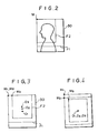
- the irradiation field adjusting means 66 operates to adjust the irradiation field to the scanning size on the stimulable phosphor sheet 30 as shown in Figure 3.
- the adjustment of the irradiation field is effected so that, for example, centers of the irradiation fields in the horizontal direction in Figure 3 align with each other and the upper sides or the lower sides of the respective irradiation fields coincide with each other. Therefore, centers O1, O2, O3 of the respective recording regions deviate vertically in Figure 3.
- the radiation source moving means 65 receives scanning size designation signal S3', it moves the radiation source 42 to the center O1, O2 or O3 of the recording region adjusted by the scanning size designation signal S3'. Therefore, for example, the head general image recording is conducted over the region of the 254mmx305mm size as indicated by F2 in Figure 3. In this case, since the irradiation field is adjusted as described above, no image of the object portion outside of the head region is recorded on the stimulable phosphor sheet 30.
- the control section 62 detects the sheet conveyance condition, for example, by receiving a signal representing conveyance of the stimulable phosphor sheet 30 from a sheet conveyance control circuit (not shown) for controlling the conveyance and circulation of the sheet 30.
- the control section 62 reads the scanning size designation signal S3' stored in the storage means 62C, and sends the signal S3' to the drive control circuit 64 for the galvanometer mirror 54 and the endless belt 8.
- the drive control circuit 64 controls operations of the galvanometer mirror 54 and the endless belt 8 so that scanning of the sheet 30 with the laser beam 52 is conducted over the scanning size represented by the signal S3'.
- the drive control circuit 64 adjusts the starting point of scanning to M1, M2 or M3 depending on the scanning size so that the scanning with the laser beam 52 is conducted over the recording region positioned as shown in Figure 3.
- the image recording stand 41 should be provided with marks respectively corresponding to a plurality of the scanning sizes as mentioned above, so that the image of an object portion is recorded exactly within each size.
- the starting point of scanning need not necessarily be changed when the size of scanning with stimulating rays is changed.
- the starting point of scanning may be maintained constant when the size of scanning with stimulating rays is changed.
- the scanning size is adjusted either to the overall area of the sheet 30, i.e. to the 356mmx432mm size, or to the 356mmx356mm size as indicated by F1 smaller than the size of the sheet 30, or to the 254mmx305mm size as indicated by F2, or to some other size.
- the starting point of scanning is adjusted to a point M at the corner of each size.
- the minimum necessary scanning size for an image recording menu is equal to the image recording size optimal for the image recording menu.
- the head general image recording is carried out generally exactly over the 254mmx305mm size as shown in Figure 2.
- the stimulable phosphor sheet 30 is larger than the 254mmx305mm size, an image of an object portion outside of the head is also recorded on the sheet 30.
- the image recording menu signal S2 representing the head general image recording is entered to the control section 62, and the scanning size designation signal S3 representing the corresponding scanning size, i.e. the 254mmx305mm size, is generated by the control section 62. Therefore, image read-out is conducted only over the 254mmx305mm size.
- the image read-out processing speed becomes high.
- the image recording menu signal S2 should not be entered to the control section 62.
- the apparatus should preferably be constituted so that, in this case, image read-out is conducted automatically over the entire area of the stimulable phosphor sheet 30, or conducted over a region adjusted manually.
Landscapes
- Physics & Mathematics (AREA)
- General Physics & Mathematics (AREA)
- Facsimile Scanning Arrangements (AREA)
- Radiography Using Non-Light Waves (AREA)
- Apparatus For Radiation Diagnosis (AREA)
- Facsimiles In General (AREA)
Claims (6)
- Gerät zum Aufzeichnen und Auslesen von Strahlungsbildern, versehen mit:i) einer Zirkulations- und Fördereinrichtung (1, 25) zum Fördern einer Mehrzahl von stimulierbaren Phosphorfolien (30) zum Aufzeichnen eines Strahlungsbildes auf diesen entlang eines vorgegebenen Zirkulationsweges (26),ii) einem Bildaufzeichnungsabschnitt (40), angeordnet auf dem Zirkulationsweg zum Aufzeichnen eines Strahlungsbildes eines Objektes (43) auf jeder der stimulierbaren Phosphorfolien, in dem die stimmulierbare Phosphorfolie einer Strahlung ausgesetzt wird, die durch das Objekt hindurchgeht,iii) einem Bildausleseabschnitt (50), angeordnet auf dem Zirkulationsweg (26) und versehen mit einer stimulierenden Strahlungsquelle (51) zur Emission stimulierender Strahlen zum Abtasten der stimulierbaren Phosphorfolien, die das Strahlungsbild tragen, das auf diesen in dem Bildaufzeichnungsabschnitt gespeichert wurde, und einer fotoelektrischen Ausleseeinrichtung (57) zur Erfassung von Licht, das durch die stimulierbare Phosphorfolie, die durch die stimulierenden Strahlen abgetastet wird, emittiert wird, um ein elektrisches Bildsignal zu erhalten, undiv) einem Löschabschnitt (70), der auf dem Zirkulationsweg angeordnet ist, um vor dem nächsten Bildaufzeichnen auf der stimulierbaren Phosphorfolie, für die ein Bildauslesevorgang in dem Bildausleseabschnitt durchgeführt worden ist, die stimulierbare Phosphorfolie zu veranlassen, die Strahlungsenergie abzugeben, die auf der stimulierbaren Phosphorfolie verbleibt,v) einem Steuerabschnitt (62), der ein Signal aufnimmt, das auf die Bildaufzeichnung bezogen ist und von dieser abhängt und die ein Signal zur Bezeichnung der Abtastgröße (S3) an den Bildausleseabschnitt (50) gibt,vi) wobei der Bildausleseabschnitt (50) so aufgebaut ist, daß eine Abtastgröße des stimulierenden Strahles in bezug auf die stimulierbare Phosphorfolie veränderbar ist, und daß der Bildaufnahmeabschnitt (50) das die Abtastgröße bezeichnende Signal (S3) aufnimmt und die Abstastgröße des stimulierenden Strahles auf eine Abtastgröße einstellt, die durch das die Abtastgröße bezeichnende Signal repräsentiert wird,vii) wobei der Bildaufzeichnungsabschnitt mit einer Bestrahlungsfeld-Einstelleinrichtung (65, 66) zum Einstellen eines Bestrahlungsfeldes auf einen Bereich auf der stimulierbaren Phosphorfolie versehen ist, auf dem die Abtastung mit den stimulierenden Strahlen ausgeführt wird,
dadurch gekennzeichnet, daßviii) der Bildaufzeichnungsabschnitt außerdem mit einer Einrichtung (65) zur Bewegung einer Strahlungsquelle (42) zur Emittierung der Strahlung verbunden ist,ix) der Steuerabschnitt (62) als ein Steuerabschnitt zur Speicherung von Kombinationen von Bildaufzeichnungsprogrammen mit Abtastgrößen für den stimulierenden Strahl in einer Speichereinrichtung (62A) ausgebildet ist,x) der Steuerabschnitt (62) ein Signal (S2) aufnimmt, das eines der Bildaufzeichnungsprogramme, wie ausgewählt, repräsentiert,xi) der Steuerabschnitt (62) die Abtastgröße entsprechend dem ausgewählten Bildaufzeichnungsprogramm, repräsentiert durch die Signale (S2) aus der Speichereinrichtung (62A), liest, undxii) der Steuerabschnitt (62) ein Signal als das die Abtastgröße bezeichnete Signal (S3) an den Bildausleseabschnitt (50) aussendet, das die Abtastgröße repräsentiert. - Gerät nach Anspruch 1, bei dem der Bildausleseabschnitt (50) eine Lichtablenkeinrichtung (54) aufweist, zum Abtasten mit den stimulierenden Strahlen auf der stimulierbaren Phosphofolie in einer Hauptabtastrichtung, und eine Folienbewegungseinrichtung (8) zum Bewegen der stimulierbaren Phosphorfolie in einer Unter-Abtastrichtung, während die stimulierbare Phosphorfolie mit den stimulierenden Strahlen in der Haupt-Abtastrichtung abgetastet wird.
- Gerät nach Anspruch 2, bei dem der Bildausleseabschnitt so ausgebildet ist, daß er die Abtastgröße des stimulierenden Strahles in bezug auf die stimulierbare Phosphorfolie durch Steuern des Betriebes der Lichtablenkeinrichtung (54) und der Folienbewegungseinrichtung (8) verändert.
- Gerät nach Anspruch 1, 2 oder 3, bei dem der Bildaufzeichnungsabschnitt (40) mit Markierungen versehen ist, die den Abtastgrößen für den stimulierenden Strahl entsprechen.
- Gerät nach einem der vorhergehenden Ansprüche, bei dem der Steuerabschnitt (62, 64) das die Abtastgröße bezeichnende Signal (S3) auch an die Bewegungseinrichtung (65) für die Strahlungsquelle und die Bestrahlungsfeld-Einstelleinrichtung (66) sendet.
- Gerät nach zumindest Anspruch 1, bei dem der Bildausleseabschnitt (50) so ausgebildet ist, daß er einen Startpunkt der Abtastung in Übereinstimmung mit der Abtastgröße verändert.
Applications Claiming Priority (2)
| Application Number | Priority Date | Filing Date | Title |
|---|---|---|---|
| JP60194218A JPS6254247A (ja) | 1985-09-03 | 1985-09-03 | 放射線画像情報記録読取装置 |
| JP194218/85 | 1985-09-03 |
Publications (2)
| Publication Number | Publication Date |
|---|---|
| EP0218094A1 EP0218094A1 (de) | 1987-04-15 |
| EP0218094B1 true EP0218094B1 (de) | 1992-07-29 |
Family
ID=16320916
Family Applications (1)
| Application Number | Title | Priority Date | Filing Date |
|---|---|---|---|
| EP86112174A Expired EP0218094B1 (de) | 1985-09-03 | 1986-09-03 | Gerät zum Aufzeichnen und Wiedergeben von Strahlungsbildern |
Country Status (4)
| Country | Link |
|---|---|
| US (1) | US4939367A (de) |
| EP (1) | EP0218094B1 (de) |
| JP (1) | JPS6254247A (de) |
| DE (1) | DE3686227T2 (de) |
Families Citing this family (6)
| Publication number | Priority date | Publication date | Assignee | Title |
|---|---|---|---|---|
| DE3814089A1 (de) * | 1987-04-27 | 1988-11-17 | Toshiba Kawasaki Kk | Verfahren und anordnung zum wiedergeben von reihenbildern |
| CA2090717A1 (en) * | 1992-03-03 | 1993-09-04 | David M. Heffelfinger | Fiber optic storage phosphor imaging plate scanner |
| JP3946809B2 (ja) * | 1996-09-30 | 2007-07-18 | 富士フイルム株式会社 | 放射線画像処理方法および装置 |
| US6317510B1 (en) * | 1997-12-19 | 2001-11-13 | Fuji Photo Film Co., Ltd. | Blackening processing method and apparatus |
| US6713776B2 (en) | 1999-12-28 | 2004-03-30 | Fuji Photo Film Co., Ltd. | Method for storing and reproducing radiation image and radiation image storage device |
| EP1416708A1 (de) * | 2002-10-28 | 2004-05-06 | Fuji Photo Film Co., Ltd. | Bildleseverfahren und -vorrichtung |
Family Cites Families (10)
| Publication number | Priority date | Publication date | Assignee | Title |
|---|---|---|---|---|
| DE2745883A1 (de) * | 1977-10-12 | 1979-04-19 | Siemens Ag | Roentgenuntersuchungsgeraet |
| JPS5512429A (en) * | 1978-07-12 | 1980-01-29 | Fuji Photo Film Co Ltd | Radioactive image reader |
| US4315318A (en) * | 1978-12-26 | 1982-02-09 | Fuji Photo Film Co., Ltd. | Method and apparatus for processing a radiation image |
| JPS55116340A (en) * | 1979-02-28 | 1980-09-06 | Fuji Photo Film Co Ltd | Method and device for processing gradation of radiation picture |
| JPS5611392A (en) * | 1979-07-11 | 1981-02-04 | Fuji Photo Film Co Ltd | Method and device for converting radiation image |
| JPS5611395A (en) * | 1979-07-11 | 1981-02-04 | Fuji Photo Film Co Ltd | Radiation image writeereading device |
| JPS56104645A (en) * | 1979-12-25 | 1981-08-20 | Fuji Photo Film Co Ltd | Radiation picture treating method and its device |
| JPS5928144A (ja) * | 1982-08-09 | 1984-02-14 | Fuji Photo Film Co Ltd | 放射線画像再生装置 |
| JPS6032044A (ja) * | 1983-08-02 | 1985-02-19 | Toshiba Corp | 放射線撮影装置 |
| JPS6088937A (ja) * | 1983-10-21 | 1985-05-18 | Fuji Photo Film Co Ltd | 放射線画像情報記録読取装置 |
-
1985
- 1985-09-03 JP JP60194218A patent/JPS6254247A/ja active Pending
-
1986
- 1986-09-03 DE DE8686112174T patent/DE3686227T2/de not_active Expired - Lifetime
- 1986-09-03 EP EP86112174A patent/EP0218094B1/de not_active Expired
-
1989
- 1989-01-18 US US07/298,817 patent/US4939367A/en not_active Expired - Lifetime
Also Published As
| Publication number | Publication date |
|---|---|
| US4939367A (en) | 1990-07-03 |
| DE3686227D1 (de) | 1992-09-03 |
| DE3686227T2 (de) | 1992-12-17 |
| EP0218094A1 (de) | 1987-04-15 |
| JPS6254247A (ja) | 1987-03-09 |
Similar Documents
| Publication | Publication Date | Title |
|---|---|---|
| EP0125800B1 (de) | Strahlungsbildaufzeichnungs- und Wiedergabevorrichtung | |
| EP0142709B1 (de) | Vorrichtung zum Aufzeichnen und Wiedergeben von Strahlungsbildern | |
| US4859849A (en) | Radiation image recording and read-out apparatus | |
| EP0182095B1 (de) | Strahlungsbildaufzeichnungs- und -Wiedergabevorrichtung mit der Möglichkeit der Darstellung von Objektdaten | |
| US4760256A (en) | Radiation image recording and read-out apparatus | |
| EP0218094B1 (de) | Gerät zum Aufzeichnen und Wiedergeben von Strahlungsbildern | |
| EP0172417B1 (de) | Strahlungsbildaufzeichnungs- und Wiedergabevorrichtung | |
| US4816680A (en) | Radiation image recording and read-out apparatus | |
| EP0178677B1 (de) | Verfahren zur Aufnahme und Wiedergabe von Strahlungsbildern | |
| EP0183040B1 (de) | Strahlungsbildaufnahme- und -wiedergabevorrichtung | |
| EP0179411B1 (de) | Vorrichtung für die Aufnahme und die Wiedergabe eines Strahlungsbildes | |
| US4754137A (en) | Tomographic type panoramic radiation image recording and read-out apparatus | |
| US4719356A (en) | Endless circulating conveying system for radiation image recording and read-out apparatus | |
| JPS6198343A (ja) | 放射線画像情報記録読取装置 | |
| JP2524298B2 (ja) | 放射線画像情報記録読取装置 | |
| JP2537599B2 (ja) | 放射線画像情報記録読取システム | |
| US4733076A (en) | Radiation image recording and read-out apparatus | |
| JPS63131134A (ja) | 放射線画像情報記録読取装置 | |
| JPS6139038A (ja) | 放射線画像情報記録読取装置 | |
| JPH0322610B2 (de) | ||
| JPH05119414A (ja) | 放射線画像情報読取方法 | |
| JPH0678907A (ja) | サブトラクション画像形成装置 | |
| JPH03157638A (ja) | 放射線画像情報記録読取再生方法 | |
| JPH0680456B2 (ja) | 放射線画像情報記録読取装置 | |
| JPH03125133A (ja) | 放射線画像記録読取装置 |
Legal Events
| Date | Code | Title | Description |
|---|---|---|---|
| PUAI | Public reference made under article 153(3) epc to a published international application that has entered the european phase |
Free format text: ORIGINAL CODE: 0009012 |
|
| AK | Designated contracting states |
Kind code of ref document: A1 Designated state(s): DE FR NL |
|
| 17P | Request for examination filed |
Effective date: 19871012 |
|
| 17Q | First examination report despatched |
Effective date: 19890112 |
|
| GRAA | (expected) grant |
Free format text: ORIGINAL CODE: 0009210 |
|
| AK | Designated contracting states |
Kind code of ref document: B1 Designated state(s): DE FR NL |
|
| REF | Corresponds to: |
Ref document number: 3686227 Country of ref document: DE Date of ref document: 19920903 |
|
| ET | Fr: translation filed | ||
| PLBE | No opposition filed within time limit |
Free format text: ORIGINAL CODE: 0009261 |
|
| STAA | Information on the status of an ep patent application or granted ep patent |
Free format text: STATUS: NO OPPOSITION FILED WITHIN TIME LIMIT |
|
| 26N | No opposition filed | ||
| PGFP | Annual fee paid to national office [announced via postgrant information from national office to epo] |
Ref country code: NL Payment date: 20050816 Year of fee payment: 20 |
|
| PGFP | Annual fee paid to national office [announced via postgrant information from national office to epo] |
Ref country code: FR Payment date: 20050919 Year of fee payment: 20 |
|
| PGFP | Annual fee paid to national office [announced via postgrant information from national office to epo] |
Ref country code: DE Payment date: 20051031 Year of fee payment: 20 |
|
| PG25 | Lapsed in a contracting state [announced via postgrant information from national office to epo] |
Ref country code: NL Free format text: LAPSE BECAUSE OF EXPIRATION OF PROTECTION Effective date: 20060903 |
|
| NLV7 | Nl: ceased due to reaching the maximum lifetime of a patent |
Effective date: 20060903 |