EP0218136A1 - Tête roulant pour le stucage automatique des surfaces des pierres, marbres ou similaires - Google Patents
Tête roulant pour le stucage automatique des surfaces des pierres, marbres ou similaires Download PDFInfo
- Publication number
- EP0218136A1 EP0218136A1 EP86113000A EP86113000A EP0218136A1 EP 0218136 A1 EP0218136 A1 EP 0218136A1 EP 86113000 A EP86113000 A EP 86113000A EP 86113000 A EP86113000 A EP 86113000A EP 0218136 A1 EP0218136 A1 EP 0218136A1
- Authority
- EP
- European Patent Office
- Prior art keywords
- putty
- spatulas
- order
- rolling head
- stuccoing
- Prior art date
- Legal status (The legal status is an assumption and is not a legal conclusion. Google has not performed a legal analysis and makes no representation as to the accuracy of the status listed.)
- Granted
Links
Images
Classifications
-
- E—FIXED CONSTRUCTIONS
- E04—BUILDING
- E04F—FINISHING WORK ON BUILDINGS, e.g. STAIRS, FLOORS
- E04F21/00—Implements for finishing work on buildings
- E04F21/20—Implements for finishing work on buildings for laying flooring
- E04F21/24—Implements for finishing work on buildings for laying flooring of masses made in situ, e.g. smoothing tools
- E04F21/245—Rotary power trowels, i.e. helicopter trowels
-
- B—PERFORMING OPERATIONS; TRANSPORTING
- B05—SPRAYING OR ATOMISING IN GENERAL; APPLYING FLUENT MATERIALS TO SURFACES, IN GENERAL
- B05C—APPARATUS FOR APPLYING FLUENT MATERIALS TO SURFACES, IN GENERAL
- B05C11/00—Component parts, details or accessories not specifically provided for in groups B05C1/00 - B05C9/00
- B05C11/02—Apparatus for spreading or distributing liquids or other fluent materials already applied to a surface ; Controlling means therefor; Control of the thickness of a coating by spreading or distributing liquids or other fluent materials already applied to the coated surface
- B05C11/04—Apparatus for spreading or distributing liquids or other fluent materials already applied to a surface ; Controlling means therefor; Control of the thickness of a coating by spreading or distributing liquids or other fluent materials already applied to the coated surface with blades
- B05C11/041—Apparatus for spreading or distributing liquids or other fluent materials already applied to a surface ; Controlling means therefor; Control of the thickness of a coating by spreading or distributing liquids or other fluent materials already applied to the coated surface with blades characterised by means for positioning, loading, or deforming the blades
-
- E—FIXED CONSTRUCTIONS
- E04—BUILDING
- E04F—FINISHING WORK ON BUILDINGS, e.g. STAIRS, FLOORS
- E04F21/00—Implements for finishing work on buildings
- E04F21/165—Implements for finishing work on buildings for finishing joints, e.g. implements for raking or filling joints, jointers
- E04F21/1652—Implements for finishing work on buildings for finishing joints, e.g. implements for raking or filling joints, jointers for smoothing and shaping joint compound to a desired contour
Definitions
- the present invention aims to achieve a rolling head, provided with inclined spatulas and orientable on its vertical axis, with which it is possible to perform automatic stuccoing of the surface of stone materials, with any type of sealant, either cement type as resins.
- Stuccoing with the aforementioned devices, is however not always effective for the various reasons, for example the reduced filling of the pores, but also for the difficulties of coating caused by the rapid hardening of the putty.
- the invention aims to obviate these drawbacks.
- the eccedent part on the contrary will have the tendency to flow on the part already released from the action of the spatula.
- This movement requires a determined time which depends on the degree of viscosity of the putty used.
- the spatulas each supported by a pendulum arm integral with the shaft, with a substantially radial arrangement and at a certain interval relative to each other and more than the disk rotation velocity is such that once the filling of a cavity, the successive passage of the spatulas does not change the situation.
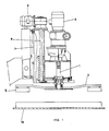
- the rolling head comprises a shaft 1, which is rotated by a variable speed drive 2, the velocity of which is arranged as a function of the diameter of the spatulas 4.
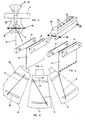
- the spatulas 4 (fig. 2) are locked between two jaws 8 and 9, of semi-cylindrical shape, retained between a vice (fig. 3) both mounted on the spatula holder arm 3, by means of clamps 11 and 12, which allow the variation of the orientation, respect for the radial direction of the carrier arms 3.
- On the vice 10 (fig. 3) two series of holes 13 and 14 are made, for example three holes each, to allow the movement in the longitudinal direction of the vice 10, in the radial direction of the support arm spatula 3.
- each spatula In angular direction on the contrary the orientation of each spatula can be varied, because of the presence of oblong holes in sector 15 and 16 (fig. 5) among which pass the locking screws 11 and 12, which fix the position of the vice 10.
- spatulas 4, illustrated in fig. 3 have a serrated edge
- spatulas 4, illustrated in FIG. 4 have a smooth edge.
- spatulas 4 are arranged so as to tend to return the putty towards the outside while the spatulas 4 'tend to approach the putty towards the center of the rotating head when the direction of rotation of the same disc is what is indicated by the arrow 17.
- each spatula 4 or 4 ′ is gripped between two semi-cylindrical jaws 8 and 9, having the possibility of being tilted more or less as necessary, respecting the work plan 18 (fig. 1).
- the cups 19 and 20 prevent the accidental scrolling of the spatulas 4 and 4 'of the vice 10.
Landscapes
- Engineering & Computer Science (AREA)
- Architecture (AREA)
- Civil Engineering (AREA)
- Structural Engineering (AREA)
- Coating Apparatus (AREA)
- Devices For Post-Treatments, Processing, Supply, Discharge, And Other Processes (AREA)
- Spray Control Apparatus (AREA)
- Finishing Walls (AREA)
- Paper (AREA)
- Absorbent Articles And Supports Therefor (AREA)
Abstract
Description
- La presente invention a le but de realiser une tête roulant, munie de spatules inclinées et orientables sur son axe vertical, avec laquelle est possible effectuer le stucage automatique de la surface des matériels de pierres, avec n'importe quel type de mastic, soit du type en ciment que des resines.
- On connait que à l'état actuel de la tecnique on prevoit la possibilité de stuquer des surfaces de material en pierre ou agglomeré, seulement dans le cas ou le dite stucage est effectué avec un liant a base de ciment.
Dans le cas des liants en matériel des resines, doivent être employé des dispositifs, munis de spatules, qui réalisent un mouvement alternatif ou aussi roulant. - Soit dans le premier cas que dans le second cas toutefois doivent être prevus des recipients, pour éviter la fuite du mastic, qui a la tendance à éviter l'action des spatules.
- Soit dans le premier cas que dans le second cas toutefois doivent être prevus des recipients, pour eviter la fuite du mastic, qui a la tendance à éviter l'action des spatules.
- Le stucage, avec les dispositifs surcités, n'est toutefois toujours efficace pour les divers raisons, pour examples le reduit remplissage des pores, mais aussi pour les difficultés d'enduisage causée par le rapide durcissement du mastic.
- L'invention a le but d'obvier à ces inconvenients.
- On a en effect verifié, en raison de l'experience, que, pour obtenir un stucage obtimal, on doit tenir compte de la viscosité du mastic qu'on doit enduire, en raison du fait que l'interval de temps, qui doit s'écouler entre le passage des deux spatules successives sur un pore à stuquer, doit être plus grand de ce qui est du par le mastic, pour ce reporter à la situation d'équilibre.
- On a pu en effect noter qu'une spatule, entrainant le mastic à ecouler, lorsqu'il passe sur une cavité qui est dans le marbre, fait confluer à l'intérieur de la même, une partie du mastic, en realisant une action de damage.
- La partie eccedente au contraire aura la tendence à s'écouler sur la partie déjà liberée de l'action de la spatule.
- Ce mouvement demand un temps determiné qui dépend du degré de la viscosité du mastic employé.
- Une fois établi l'équilibre dans le temps d'attente, on obtiendra une cavité recouverte d'une quantité de mastic excédant, delimitée par une surface convexe.
- On a noté que seulement lorsqu'y a été rejoint ce degré d'équilibre, il est possibile de faire passer une autre spatule sur le même, sans modifier le degré de recouvrement de la cavité.
- Si une spatule doit passer avant que le mastic a rattrapé l'équilibre à l'interieur du trou, il sera emporté une certaine quantité de mastic, donnant lieu à un pore non perfaitement stuqué.
- Dans la disposition selon l'invention, on prevoit que les spatules, checune soutenue par un bras portespatules solidair à l'arbre, avec une disposition substantiellement radiale et à un certain interval l'une par rapport à l'autre et de plus que la velocité de rotation du disque soit tel qu'une fois effectué le remplissage d'une cavité, le successif passage des spatules n'en modifie pas la situation.
- On a en suite remarqué qu'il semble opportun que le bord inferieur d'une des spatules, exactement celle qui tend à déplacer le mastic vers l'exterieur, soit dentelé, à fin d'augmenter la pressione spécifique appliquée sur la surface à stuquer.
- Pour ce qui concerne le nombre des tours de la tête rotative on doit rélever qu'il depend du nombre des spatules montées sur la même et en plus du degré de la viscosité du mastic.
- Clairement pour des mastics plus visqueux, la velocité de rotation devra être mineure en relation aux mastics plus fluides.
L'invention sera ici de suite descripte en détail à l'aide des tables de dessins ci jointes, dans lesquelles: - la fig. 1 représente la vue complexive squematique de coté de la tête roulante, en partie sectionnée.
- La fig. 2 représente, dans la vue de profil une des spatules montées sur les bras qui porte la spatule duquel est visible une part.
- La fig. 3 répresente, dans la vue en perspective, une spatule à bord dentelée, avec ses dispositifs de bloccage.
- La fig. 4 représente, toujours dans la vue en perspective, une spatule à bord lisse, avec ses dispositivs de mise en place.
- La fig. 5 représente en manière schematisée la disposition de certaines spatules radiales sur les relatifs bras portants les spatules.
- Comme on peut voir en particulier en fig. 1, la tête roulante comprend un arbre 1, qui est mis en rotation par un motovariateur 2, duquel la velocité est disposé en fonction du diamètre des spatules 4.
- Le motoriducteur 5, au moyen de la vis 6, provoque le déplacement dans le sens vertical de la tête par rapport aux guides 7, en consentent le soulevement des bras porte-spatules 3 et des relatives spatules 4.
Les spatules 4 (fig. 2) sont bloquèes entre deux mâchoires 8 et 9, de forme hémicylindrique, retenues entre une étau (fig. 3) à la fois monté sur le bras porte-spatule 3, au moyen des étaux 11 et 12, qui en permettent la variation de l'orientation, respect à la direction radiale des bras portespatules 3.
Sur l'étau 10 (fig. 3) sont pratiquées deux series de troux 13 et 14, pour example de trois troux chacune, pour permettre le déplacement en sens longitudinal de l'étau 10, dans la direction radiale du bras portespatule 3. - En sens angulair au contraire l'orientation de chaque spatule peut être variée, à cause de la présence des troux oblongs à secteur 15 et 16 (fig. 5) parmi lesquels passent les vis de bloquage 11 et 12, qui fixent la position de l'étau 10.
- On notera que tandis les spatules 4, illustrées en fig. 3, présentent un bord dentelé, les spatules 4, illustrées en fig. 4 présentent un bord lisse.
- Soit les spatules 4, soit les spatules 4' sont montées en manière à pouvoir se disposer en manière different respect le cours de la direction radiale du bras portespatule 3, étants prevues des rainures à secteur circulair 15 et 16, qui en permettent la variation de l'orientation.
- En particulièr on prevoit que les spatules 4 soient disposées en manière à tendre à renvoyer le mastic vers l'extérieur tandis que les spatules 4' tendent à approcher le mastic vers le centre de la tête tournant quand le sens de rotation du même disque est ce qui est indiqué par la flêche 17.
- En telle manière on évite que la mastic soit centrifugué vers l'exterieur ou l'interieur de la surface interessée à l'operation de stucage.
- On notera aussi que chaque spatule 4 ou 4' est saisie entre deux machoires demicilindriques 8 et 9, ayant la possibilité d'être inclinées plus ou moin selon les necessités, respect le plan de travail 18 (fig. 1).
Les coupilles 19 et 20 évitent le defilage accidental des spatules 4 et 4' du étau 10.
Les spatules 4 et 4' évidemment se penchent pendant le travail roulant jusqu'à s'appuier contre le bord de l'étau 10 (voir le dessin à hachure en fig. 2).
Ce au but d'exerciter sur la dalle en travail toujours le même degré de pression. - Naturellement les particuliers constructifs de detail de la machine de l'invention pourrons assumer des formes et d'aspects differents, toujours etant les mêmes les caractéristiques exentiels de l'inventions, sans pour cela sortir du cadre du brévêt.
Claims (5)
Priority Applications (1)
| Application Number | Priority Date | Filing Date | Title |
|---|---|---|---|
| AT86113000T ATE67549T1 (de) | 1985-09-30 | 1986-09-20 | Rotierender kopf fuer die automatische stuckarbeit der oberflaechen von steinen, marmor oder dergleichen. |
Applications Claiming Priority (2)
| Application Number | Priority Date | Filing Date | Title |
|---|---|---|---|
| IT8560085 | 1985-09-30 | ||
| IT85600/85A IT1188026B (it) | 1985-09-30 | 1985-09-30 | Testa rotante per la stuccatura automatica di materiali lapidei |
Publications (2)
| Publication Number | Publication Date |
|---|---|
| EP0218136A1 true EP0218136A1 (fr) | 1987-04-15 |
| EP0218136B1 EP0218136B1 (fr) | 1991-09-18 |
Family
ID=11328757
Family Applications (1)
| Application Number | Title | Priority Date | Filing Date |
|---|---|---|---|
| EP86113000A Expired - Lifetime EP0218136B1 (fr) | 1985-09-30 | 1986-09-20 | Tête roulant pour le stucage automatique des surfaces des pierres, marbres ou similaires |
Country Status (9)
| Country | Link |
|---|---|
| US (1) | US4738218A (fr) |
| EP (1) | EP0218136B1 (fr) |
| JP (1) | JPH0434941Y2 (fr) |
| CN (1) | CN1005465B (fr) |
| AT (1) | ATE67549T1 (fr) |
| CA (1) | CA1256280A (fr) |
| DE (1) | DE3681545D1 (fr) |
| ES (1) | ES1001328Y (fr) |
| IT (1) | IT1188026B (fr) |
Cited By (2)
| Publication number | Priority date | Publication date | Assignee | Title |
|---|---|---|---|---|
| FR2783963A1 (fr) * | 1998-09-29 | 2000-03-31 | Cogema | Dispositif de surfacage |
| CN110528889A (zh) * | 2019-08-26 | 2019-12-03 | 广东博智林机器人有限公司 | 刮平抹平机器人 |
Families Citing this family (10)
| Publication number | Priority date | Publication date | Assignee | Title |
|---|---|---|---|---|
| US5318629A (en) * | 1992-01-02 | 1994-06-07 | Raque Food Systems, Inc. | Spreading apparatus for spreading a material on continuously moving objects |
| US20040161546A1 (en) * | 2000-10-10 | 2004-08-19 | Clemmer Clay E. | Method Of Making A Stone Veneer |
| TR200201947A2 (tr) * | 2001-12-14 | 2004-02-23 | Munoz Albinana Jose | Yapı için düz parçaların yada levhaların otomatik olarak reçinelenmesini sağlayan makine |
| US20060025059A1 (en) * | 2004-07-28 | 2006-02-02 | Gueorguiev Gueorgui D | Concrete polishing system |
| US7771249B2 (en) * | 2007-03-30 | 2010-08-10 | Park Industries, Inc. | Corner saw |
| US10201914B2 (en) | 2015-01-20 | 2019-02-12 | Park Industries, Inc. | Material loading apparatus |
| CN107597736B (zh) * | 2017-10-08 | 2021-08-31 | 池州市芯村里新材料科技有限公司 | 一种餐桌玻璃转盘油污免冲洗清洁胶实施工具 |
| CN110548928A (zh) * | 2018-06-04 | 2019-12-10 | 凤城市世林机械有限责任公司 | 圆盘形工件抹腻子装置及加工方法 |
| CN110424690B (zh) * | 2019-08-08 | 2020-11-03 | 广东博智林机器人有限公司 | 一种刮腻子机器人 |
| US11891821B2 (en) * | 2021-10-14 | 2024-02-06 | John H. Kipp, Jr. | Mini-concrete trowel attachment assembly |
Citations (5)
| Publication number | Priority date | Publication date | Assignee | Title |
|---|---|---|---|---|
| FR1195455A (fr) * | 1958-04-28 | 1959-11-17 | Outil rotatif de raclage | |
| US3130653A (en) * | 1961-04-04 | 1964-04-28 | David R Talbott | Surfacing machine |
| DE2035465A1 (de) * | 1970-07-17 | 1972-01-20 | Eberle, Leonhard, 8873 Buhl | Putzhobel fur Putzarbeiten |
| DE2733419A1 (de) * | 1977-07-23 | 1979-02-01 | Erich Hofmann | Vorrichtung zum verdichten und/oder glaetten von frischem beton o.dgl. |
| FR2485597A1 (fr) * | 1980-06-25 | 1981-12-31 | Johansson Leif | Dispositif d'application a la truelle d'un produit sur une surface |
Family Cites Families (4)
| Publication number | Priority date | Publication date | Assignee | Title |
|---|---|---|---|---|
| US2156873A (en) * | 1937-12-27 | 1939-05-02 | J W Mortell Company | Measuring and troweling machine |
| CA916867A (en) * | 1970-06-03 | 1972-12-19 | Horst Elias | Sweeper |
| US4219898A (en) * | 1979-02-14 | 1980-09-02 | Presby Harry A | Floating brush floor cleaner |
| US4461127A (en) * | 1981-11-19 | 1984-07-24 | The Boeing Company | Abrading tool |
-
1985
- 1985-09-30 IT IT85600/85A patent/IT1188026B/it active
-
1986
- 1986-09-20 AT AT86113000T patent/ATE67549T1/de not_active IP Right Cessation
- 1986-09-20 EP EP86113000A patent/EP0218136B1/fr not_active Expired - Lifetime
- 1986-09-20 DE DE8686113000T patent/DE3681545D1/de not_active Expired - Lifetime
- 1986-09-24 US US06/911,493 patent/US4738218A/en not_active Expired - Fee Related
- 1986-09-24 CA CA000518953A patent/CA1256280A/fr not_active Expired
- 1986-09-29 ES ES19868600602U patent/ES1001328Y/es not_active Expired
- 1986-09-30 CN CN86106997.8A patent/CN1005465B/zh not_active Expired
- 1986-09-30 JP JP1986150633U patent/JPH0434941Y2/ja not_active Expired
Patent Citations (5)
| Publication number | Priority date | Publication date | Assignee | Title |
|---|---|---|---|---|
| FR1195455A (fr) * | 1958-04-28 | 1959-11-17 | Outil rotatif de raclage | |
| US3130653A (en) * | 1961-04-04 | 1964-04-28 | David R Talbott | Surfacing machine |
| DE2035465A1 (de) * | 1970-07-17 | 1972-01-20 | Eberle, Leonhard, 8873 Buhl | Putzhobel fur Putzarbeiten |
| DE2733419A1 (de) * | 1977-07-23 | 1979-02-01 | Erich Hofmann | Vorrichtung zum verdichten und/oder glaetten von frischem beton o.dgl. |
| FR2485597A1 (fr) * | 1980-06-25 | 1981-12-31 | Johansson Leif | Dispositif d'application a la truelle d'un produit sur une surface |
Cited By (4)
| Publication number | Priority date | Publication date | Assignee | Title |
|---|---|---|---|---|
| FR2783963A1 (fr) * | 1998-09-29 | 2000-03-31 | Cogema | Dispositif de surfacage |
| WO2000018553A1 (fr) * | 1998-09-29 | 2000-04-06 | Compagnie Generale Des Matieres Nucleaires | Dispositif de surfaçage |
| US6548007B1 (en) | 1998-09-29 | 2003-04-15 | Compagnie Generale Des Matieres Nucleaires | Surfacing device |
| CN110528889A (zh) * | 2019-08-26 | 2019-12-03 | 广东博智林机器人有限公司 | 刮平抹平机器人 |
Also Published As
| Publication number | Publication date |
|---|---|
| EP0218136B1 (fr) | 1991-09-18 |
| JPS6275874U (fr) | 1987-05-15 |
| ATE67549T1 (de) | 1991-10-15 |
| CN1005465B (zh) | 1989-10-18 |
| IT8585600A0 (it) | 1985-09-30 |
| ES1001328Y (es) | 1988-12-16 |
| IT1188026B (it) | 1987-12-30 |
| CN86106997A (zh) | 1987-07-29 |
| ES1001328U (es) | 1988-05-01 |
| JPH0434941Y2 (fr) | 1992-08-19 |
| CA1256280A (fr) | 1989-06-27 |
| US4738218A (en) | 1988-04-19 |
| DE3681545D1 (de) | 1991-10-24 |
Similar Documents
| Publication | Publication Date | Title |
|---|---|---|
| EP0218136B1 (fr) | Tête roulant pour le stucage automatique des surfaces des pierres, marbres ou similaires | |
| EP0611191B1 (fr) | Machine à fraiser, percer, surfacer, moulurer et polir des pierres ou matériau similaire | |
| US6148469A (en) | Adjustable handle for edging paint roller | |
| EP1476287B1 (fr) | Tour de potier comportant un dispositif de guidage pour le formage | |
| EP0258122B1 (fr) | Engin de fraisage pour creuser des tranchées dans le sol | |
| EP0196941B1 (fr) | Dispositif de surfaçage et de polissage du chant vertical d'une pierre ou d'un élément préfabriqué massif | |
| FR2782380A1 (fr) | Dispositif de mesure de longueur | |
| FR2682315A1 (fr) | Dispositif pour fabriquer des decoupes en depouille dans des percages dans le beton et la roche et procede pour reunir deux plaques de beton comportant de tels percages . | |
| US1192416A (en) | Holder for sharpening gravers and other tools. | |
| AU2003265189A1 (en) | A tool for polishing the edge of a knife | |
| CA2975344A1 (fr) | Dispositif de pre-decoupe d'une colonne pour un sol | |
| FR2797207A1 (fr) | Procede de formation de surfaces spheriques concaves | |
| BE430747A (fr) | ||
| FR2459716A1 (fr) | Machine pour l'enlevement des revetements de surface | |
| FR2699106A1 (fr) | Installation de centrifugation de matériau liquide durcissable et ses utilisations. | |
| JPS5826788Y2 (ja) | 裁断刃 | |
| JPS608930Y2 (ja) | 面取り加工装置 | |
| FR2523818A1 (fr) | Dispositif de coupe pour tiges continues de produits a fumer | |
| GB2251574A (en) | Manually actuated potters wheel | |
| EP1669516A1 (fr) | Appareil à dresser les dalles de béton et autres agrégats | |
| FR2571650A1 (fr) | Dispositif pour le lissage d'elements en beton moules | |
| FR2663578A1 (fr) | Porte-outil oscillant pour ponceuse. | |
| GB2243801A (en) | Clamps | |
| EP0170764A1 (fr) | Rectifieuse pour vilebrequins de moteurs à explosion et diesel | |
| BE357689A (fr) |
Legal Events
| Date | Code | Title | Description |
|---|---|---|---|
| PUAI | Public reference made under article 153(3) epc to a published international application that has entered the european phase |
Free format text: ORIGINAL CODE: 0009012 |
|
| AK | Designated contracting states |
Kind code of ref document: A1 Designated state(s): AT DE FR GB IT |
|
| 17P | Request for examination filed |
Effective date: 19871020 |
|
| 17Q | First examination report despatched |
Effective date: 19881121 |
|
| GRAA | (expected) grant |
Free format text: ORIGINAL CODE: 0009210 |
|
| ITF | It: translation for a ep patent filed | ||
| AK | Designated contracting states |
Kind code of ref document: B1 Designated state(s): AT DE FR GB IT |
|
| PG25 | Lapsed in a contracting state [announced via postgrant information from national office to epo] |
Ref country code: GB Effective date: 19910918 Ref country code: AT Effective date: 19910918 |
|
| REF | Corresponds to: |
Ref document number: 67549 Country of ref document: AT Date of ref document: 19911015 Kind code of ref document: T |
|
| REF | Corresponds to: |
Ref document number: 3681545 Country of ref document: DE Date of ref document: 19911024 |
|
| GBV | Gb: ep patent (uk) treated as always having been void in accordance with gb section 77(7)/1977 [no translation filed] | ||
| PLBE | No opposition filed within time limit |
Free format text: ORIGINAL CODE: 0009261 |
|
| STAA | Information on the status of an ep patent application or granted ep patent |
Free format text: STATUS: NO OPPOSITION FILED WITHIN TIME LIMIT |
|
| PG25 | Lapsed in a contracting state [announced via postgrant information from national office to epo] |
Ref country code: FR Effective date: 19920731 |
|
| 26N | No opposition filed | ||
| REG | Reference to a national code |
Ref country code: FR Ref legal event code: ST |
|
| PGFP | Annual fee paid to national office [announced via postgrant information from national office to epo] |
Ref country code: DE Payment date: 19981125 Year of fee payment: 13 |
|
| PG25 | Lapsed in a contracting state [announced via postgrant information from national office to epo] |
Ref country code: DE Free format text: LAPSE BECAUSE OF NON-PAYMENT OF DUE FEES Effective date: 20000801 |
|
| PG25 | Lapsed in a contracting state [announced via postgrant information from national office to epo] |
Ref country code: IT Free format text: LAPSE BECAUSE OF NON-PAYMENT OF DUE FEES;WARNING: LAPSES OF ITALIAN PATENTS WITH EFFECTIVE DATE BEFORE 2007 MAY HAVE OCCURRED AT ANY TIME BEFORE 2007. THE CORRECT EFFECTIVE DATE MAY BE DIFFERENT FROM THE ONE RECORDED. Effective date: 20050920 |
|
| PG25 | Lapsed in a contracting state [announced via postgrant information from national office to epo] |
Ref country code: FR Effective date: 19910930 |