EP0218308A2 - Appareil pour détecter la position angulaire et la vitesse angulaire d'un organe rotatif et méthode d'assemblage de l'appareil - Google Patents
Appareil pour détecter la position angulaire et la vitesse angulaire d'un organe rotatif et méthode d'assemblage de l'appareil Download PDFInfo
- Publication number
- EP0218308A2 EP0218308A2 EP86201854A EP86201854A EP0218308A2 EP 0218308 A2 EP0218308 A2 EP 0218308A2 EP 86201854 A EP86201854 A EP 86201854A EP 86201854 A EP86201854 A EP 86201854A EP 0218308 A2 EP0218308 A2 EP 0218308A2
- Authority
- EP
- European Patent Office
- Prior art keywords
- sensor
- disc
- steering
- holder
- secured
- Prior art date
- Legal status (The legal status is an assumption and is not a legal conclusion. Google has not performed a legal analysis and makes no representation as to the accuracy of the status listed.)
- Granted
Links
Images


Classifications
-
- G—PHYSICS
- G01—MEASURING; TESTING
- G01P—MEASURING LINEAR OR ANGULAR SPEED, ACCELERATION, DECELERATION, OR SHOCK; INDICATING PRESENCE, ABSENCE, OR DIRECTION, OF MOVEMENT
- G01P3/00—Measuring linear or angular speed; Measuring differences of linear or angular speeds
- G01P3/42—Devices characterised by the use of electric or magnetic means
- G01P3/44—Devices characterised by the use of electric or magnetic means for measuring angular speed
- G01P3/48—Devices characterised by the use of electric or magnetic means for measuring angular speed by measuring frequency of generated current or voltage
-
- B—PERFORMING OPERATIONS; TRANSPORTING
- B62—LAND VEHICLES FOR TRAVELLING OTHERWISE THAN ON RAILS
- B62D—MOTOR VEHICLES; TRAILERS
- B62D15/00—Steering not otherwise provided for
- B62D15/02—Steering position indicators ; Steering position determination; Steering aids
-
- G—PHYSICS
- G01—MEASURING; TESTING
- G01D—MEASURING NOT SPECIALLY ADAPTED FOR A SPECIFIC VARIABLE; ARRANGEMENTS FOR MEASURING TWO OR MORE VARIABLES NOT COVERED IN A SINGLE OTHER SUBCLASS; TARIFF METERING APPARATUS; MEASURING OR TESTING NOT OTHERWISE PROVIDED FOR
- G01D5/00—Mechanical means for transferring the output of a sensing member; Means for converting the output of a sensing member to another variable where the form or nature of the sensing member does not constrain the means for converting; Transducers not specially adapted for a specific variable
- G01D5/26—Mechanical means for transferring the output of a sensing member; Means for converting the output of a sensing member to another variable where the form or nature of the sensing member does not constrain the means for converting; Transducers not specially adapted for a specific variable characterised by optical transfer means, i.e. using infrared, visible, or ultraviolet light
- G01D5/32—Mechanical means for transferring the output of a sensing member; Means for converting the output of a sensing member to another variable where the form or nature of the sensing member does not constrain the means for converting; Transducers not specially adapted for a specific variable characterised by optical transfer means, i.e. using infrared, visible, or ultraviolet light with attenuation or whole or partial obturation of beams of light
- G01D5/34—Mechanical means for transferring the output of a sensing member; Means for converting the output of a sensing member to another variable where the form or nature of the sensing member does not constrain the means for converting; Transducers not specially adapted for a specific variable characterised by optical transfer means, i.e. using infrared, visible, or ultraviolet light with attenuation or whole or partial obturation of beams of light the beams of light being detected by photocells
-
- H—ELECTRICITY
- H03—ELECTRONIC CIRCUITRY
- H03M—CODING; DECODING; CODE CONVERSION IN GENERAL
- H03M1/00—Analogue/digital conversion; Digital/analogue conversion
- H03M1/12—Analogue/digital converters
- H03M1/22—Analogue/digital converters pattern-reading type
- H03M1/24—Analogue/digital converters pattern-reading type using relatively movable reader and disc or strip
- H03M1/28—Analogue/digital converters pattern-reading type using relatively movable reader and disc or strip with non-weighted coding
- H03M1/30—Analogue/digital converters pattern-reading type using relatively movable reader and disc or strip with non-weighted coding incremental
- H03M1/301—Constructional details of parts relevant to the encoding mechanism, e.g. pattern carriers, pattern sensors
Definitions
- the present invention relates to an apparatus for detecting an angular position and an angular velocity of a rotatable member and a method of assembling it, and particularly to a steering sensor for detecting a steering angle and a steering angular velocity.
- an apparatus for detecting a steering angle and a steering angular velocity comprising a disc mounted on a steering shaft, and a sensor secured to a stationary steering column tube.
- the present applicants have described an invention concerning the way in which the sensor is mounted, in a separate Patent application.
- the disc is designed to be rotated with the steering shaft, and has a number of small holes which are concentrically located therein.
- the sensor has a light emitting element and a light receiving element, which are located on opposite sides of the disc at positions opposite the series of holes in the disc.
- GB-A-1,417,788 describes an apparatus for generating electrical pulses for each revolution of a shaft, which has the features of the preamble of Claim 1.
- the present invention was made in view of the foregoing background art. It is an object of this invention to provide an improved apparatus for detecting a steering angle and an angular velocity of a rotatable part of a steering system to overcome or minimize the aforesaid disadvantages of the known detecting apparatus whereby correct assembly is facilitated.
- the invention provides an apparatus for detecting the angular position and angular velocity of a rotatable member, comprising a disc mounted on and rotatable with the rotatable member, the disc having a number of holes located around the circumference thereof, a fixed member, a sensor secured to the fixed member and having positioned on respective opposite sides of the disc, a light emitting means and light receiving means at locations opposite said holes in the disc, wherein the disc projects radially from the rotatable member towards the sensor by a distance, and the sensor is provided with extensions in which said light emitting means and said light receiving means are located, respectively, characterized in that there is provided a holder secured to the outer periphery of the steering shaft, the holder having the disc secured thereto at a central position along the length of the holder, in that the holder comprises a first side wall extending towards the sensor, a second side wall extending towards the sensor in a parallel relationship with the first side wall, the side walls being spaced apart at a distance, and a tubular
- Figure 1 shows a perspective view of a steering system provided with an apparatus according to the present invention.
- the rotational movement of a steering wheel 10 is transmitted through a steering shaft 12 to wheels (not shown in drawings).
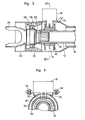
- the perspective view of the steering shaft 12 according to the present invention is shown in Figure 2.
- a disc 14, which includes a number of small holes concentrically located therein, is mounted on the outer periphery of the steering shaft 12.
- a sensor 16 is located at the outer side of the disc 14, and is secured to a steering column tube 18.
- Figure 3 shows an enlarged detailed, cross-sectional view of the apparatus according to the present invention.
- the steering column tube 18 extends downward (to the left in Figure 3), and an enlarged lower steering column tube 20 is secured to the lower portion of the steering column tube 18.
- the steering shaft 12 is inserted into the inside of the steering column tube 18.
- the upper end of the steering shaft 12 is connected with the steering wheel 10.
- the lower part of the steering shaft 12 extends into the inside of the lower steering column tube 20.
- the lower end of the steering shaft 12 is fixed by welding to a shaft portion 22 of a yoke 24.
- a lower bearing 26 is provided on the outer periphery of the shaft portion 22 of the yoke 24.
- the lower bearing 26 is secured through a retainer 28 to the inner face of the lower steering column tube 20.
- a collar 32 fits into the outer periphery of the steering shaft 12 and is welded to the steering shaft 12.
- a holder 40 is press fitted onto the outer periphery of the collar 32.
- the holder 40 has a U-shaped cross-sectional form.
- the holder 40 is to hold the disc 14 thereon.
- Figures 5 through 8 illustrate the detailed structure of the holder 40.
- the holder 40 has side walls 402 and 404, and a tubular portion 406 which connects the side walls 402 and 404.
- the disc 14 is secured to the longitudinal central point of the outer surface 408 of the tubular portion 406.
- the disc 14, as shown in Figure 4, includes a number of small holes 50, which are of the same form and are positioned concentrically with respect to the axis of the disc 14 at regularly spaced intervals.
- the lower steering column tube 20 has an aperture 52 at a position which faces the holder 40.
- the aperture 52 is square.
- the lower portion of the sensor 16 extends through the aperture 52 into the inside of the lower steering column tube 20.
- the sensor 16 is fastened by screws 54 to a sensor mounting bracket -70.
- the bracket 70 is fixed to the lower steering column tube 20, as shown in Figure 4.
- the disc 14 is designed to have a shorter height "H 1 than the height "H 2 " of the side walls 402 and 404 of the holder 40 as shown in Figure 8.
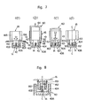
- the sensor 16 as shown in Figures 6 and 7, has a main portion 164 of a hexagonal cross-sectional form, a light emitting element 160, and a light receiving element 162, both of which are secured to the under surface of the main portion 164.
- the light emitting element 160 and the light receiving element 162 are separated from each other by a distance "L 1 ".
- the disc 14 is located on the central point of the distance "L 1 ".
- the sensor 16, as shown in Figure 6 has front side faces 165, a front intermediate side face 166, rear side faces 167, and a rear intermediate side face 168.
- the sensor 16 is symmetrical with regard to a central plane "C-C" shown in Figure 6.
- the distance between the front intermediate side face 166 and the rear intermediate side face 168 is designed to be substantially the same as that defined between the outer faces of the side walls 402 and 404 of the holder 40.
- the light emitting element 160 and the light receiving element 162 are provided, at the symmetrical positions with regard to a central plane "C-C" through the sensor 16 shown in Figure 7(d).
- the light emitting element 160 is designed to have the same thickness as that of the light receiving element 162.
- the numeral 60 designates a jig for avoiding contact of the thin disc 14 with the light emitting element 160 or the light receiving element 162 when assembling the sensor 16 in the correct position.
- the jig 60 has a pair of legs 62, and a bridge portion 64 which connects one of the legs 62 with the other leg.
- the pair of legs 62 extend in parallel with each other.
- the jig 60 has a cross-sectional form of a U-shape.
- the distance between the inner- faces of the legs 62 is designed to be the same as that defined between the front intermediate side face 166 and the rear intermediate side face 168 of the holder 40.
- the distance between the front intermediate side face and the rear intermediate side face 168 of the holder 40 is designed to be the same as that defined between the outer faces of the side walls 402 and 404
- the distance between the inner faces of the legs 62 is designed to be the same as that defined between the outer faces of the side walls 402 and 404.
- Each of the legs 62 has a tip end 66 which is inclined outward, and each of the tip ends is oppositely inclined.
- Each of the legs 62 of the jig 60 is fitted onto the outer face of the side walls 402 or 404 of the holder 40, thereby the jig 60 tightly grips the holder 40.
- the references as to the length of the sensor 16 and the holder 40 are shown in Figure 8.
- the reference L 1 is the distance between the light emitting element 160 and the light receiving element 162.
- the reference L 2 is the width or thickness of the light emitting element 160 and of the light receiving element 162.
- the reference L 3 is the distance between the disc 14 and the side walls 402 or 404 of the holder 40.
- the height of the disc 14 is indicated by the reference “H 1 ".
- the light emitting element 160 and the light receiving element 162 project toward the holder 40 by the distance "H 2 ".
- the embodiment according to the present invention has the following relation:
- the sensor 16 is assembled into the steering system according to the following procedure:
- the disc 14 When the sensor 16 is assembled in the steering column, the disc 14 does not contact the light emitting element 160.or the light receiving element 162. Hence, the disc 14 is not damaged during assembly of the steering system.
- the sensor 16 can therefore detect accurately the steering angle and the steering angular velocity. Workers can promptly assemble the sensor into the steering column by the use of the jig. Further, the jig can protect the disc from being adversely affected by striking the light emitting element or the light receiving element when the steering column is transferred.
Landscapes
- Engineering & Computer Science (AREA)
- Physics & Mathematics (AREA)
- General Physics & Mathematics (AREA)
- Chemical & Material Sciences (AREA)
- Combustion & Propulsion (AREA)
- Transportation (AREA)
- Mechanical Engineering (AREA)
- Theoretical Computer Science (AREA)
- Length Measuring Devices By Optical Means (AREA)
- Steering Controls (AREA)
- Optical Transform (AREA)
- Length Measuring Devices With Unspecified Measuring Means (AREA)
Applications Claiming Priority (2)
| Application Number | Priority Date | Filing Date | Title |
|---|---|---|---|
| JP11958/83 | 1983-01-29 | ||
| JP1983011958U JPS59117915U (ja) | 1983-01-29 | 1983-01-29 | 自動車のステアリングセンサ |
Related Parent Applications (1)
| Application Number | Title | Priority Date | Filing Date |
|---|---|---|---|
| EP84300080.3 Division | 1984-01-06 |
Publications (3)
| Publication Number | Publication Date |
|---|---|
| EP0218308A2 true EP0218308A2 (fr) | 1987-04-15 |
| EP0218308A3 EP0218308A3 (en) | 1987-08-19 |
| EP0218308B1 EP0218308B1 (fr) | 1989-03-15 |
Family
ID=11792123
Family Applications (2)
| Application Number | Title | Priority Date | Filing Date |
|---|---|---|---|
| EP86201854A Expired EP0218308B1 (fr) | 1983-01-29 | 1984-01-06 | Appareil pour détecter la position angulaire et la vitesse angulaire d'un organe rotatif et méthode d'assemblage de l'appareil |
| EP84300080A Expired EP0115381B1 (fr) | 1983-01-29 | 1984-01-06 | Appareil pour détecter la position angulaire et la vitesse angulaire d'un organe rotatif et méthode d'assemblage de l'appareil |
Family Applications After (1)
| Application Number | Title | Priority Date | Filing Date |
|---|---|---|---|
| EP84300080A Expired EP0115381B1 (fr) | 1983-01-29 | 1984-01-06 | Appareil pour détecter la position angulaire et la vitesse angulaire d'un organe rotatif et méthode d'assemblage de l'appareil |
Country Status (4)
| Country | Link |
|---|---|
| US (1) | US4614869A (fr) |
| EP (2) | EP0218308B1 (fr) |
| JP (1) | JPS59117915U (fr) |
| DE (1) | DE3470502D1 (fr) |
Cited By (2)
| Publication number | Priority date | Publication date | Assignee | Title |
|---|---|---|---|---|
| EP0290225A3 (en) * | 1987-05-04 | 1990-02-14 | Ford Motor Company Limited | Method and apparatus for determining the center position of a vehicular steering system |
| FR2735225A1 (fr) * | 1995-06-12 | 1996-12-13 | Motorola Semiconducteurs | Capteur de position optoelectronique et systeme de compensation pour un tel capteur |
Families Citing this family (16)
| Publication number | Priority date | Publication date | Assignee | Title |
|---|---|---|---|---|
| AT392536B (de) * | 1984-07-06 | 1991-04-25 | R S F Elektronik Ohg Rechtsfor | Lineares, inkrementales messsystem |
| IT1180098B (it) * | 1984-10-16 | 1987-09-23 | Fiat Auto Spa | Sensore elettrico dell'angolo di sterzatura per autoveicoli |
| US4712005A (en) * | 1985-12-19 | 1987-12-08 | Kollmorgen Technologies Corporation | Floating mask encoder with assembly spacer |
| GB2188295A (en) * | 1986-03-24 | 1987-09-30 | Linde Ag | Power-assisted steering devices |
| US4816673A (en) * | 1987-07-01 | 1989-03-28 | Motorola, Inc. | Shock proof steering module assembly |
| DE3741821C1 (de) * | 1987-12-10 | 1989-05-24 | Messerschmitt Boelkow Blohm | Winkelsensorelement |
| JPH0227506U (fr) * | 1988-08-12 | 1990-02-22 | ||
| DE3905102A1 (de) * | 1989-02-20 | 1990-08-23 | Kloeckner Humboldt Deutz Ag | Verfahren und vorrichtung zur lenkwinkelerfassung im lenkungsstrang von fahrzeugen |
| DE19506019C2 (de) * | 1995-02-22 | 2000-04-13 | Telefunken Microelectron | Verfahren zum Betrieb eines optischen Lenkwinkelsensors |
| DE19601964A1 (de) * | 1996-01-20 | 1997-07-24 | Teves Gmbh Alfred | Aufbau eines Lenkwinkelsensormuduls |
| US6145368A (en) * | 1998-06-03 | 2000-11-14 | Micron Electronics, Inc. | Method for calibrating rotary encoder with multiple calibration points |
| US6184518B1 (en) | 1998-06-03 | 2001-02-06 | Micron Electronics, Inc. | Rotary encoder with multiple calibration points |
| US6248993B1 (en) * | 1998-08-05 | 2001-06-19 | Leopold Kostal Gmbh & Co. Kg | Steering angle sensor |
| JP2002154440A (ja) * | 2000-11-17 | 2002-05-28 | Yazaki Corp | ステアリング用舵角センサの取付構造 |
| US8322483B2 (en) * | 2009-09-15 | 2012-12-04 | Robert Bosch Gmbh | Steering angle sensor |
| WO2014119345A1 (fr) | 2013-02-04 | 2014-08-07 | アルプス電気株式会社 | Élément magnétorésistif géant et capteur de courant l'utilisant |
Family Cites Families (8)
| Publication number | Priority date | Publication date | Assignee | Title |
|---|---|---|---|---|
| US3814934A (en) * | 1972-11-10 | 1974-06-04 | Gilbert & Barker Mfg Co | Pulse generating apparatus responsive to shaft rotation |
| US3894232A (en) * | 1974-05-08 | 1975-07-08 | Teletype Corp | Rotationally adjustable support mechanism |
| US4117320A (en) * | 1976-06-08 | 1978-09-26 | Carson (Instruments & Equipment) Limited | Digital measuring instruments |
| IT1116276B (it) * | 1977-12-30 | 1986-02-10 | Olivetti & Co Spa | Trasduttore di posizione angolare per un organo ruotante |
| GB2024122B (en) * | 1978-06-30 | 1982-09-22 | Towmotor Corp | Steering wheel assembly |
| DE2848612C2 (de) * | 1978-11-09 | 1981-05-27 | Pfaff Haushaltsmaschinen GmbH, 7500 Karlsruhe | Impulsgeber eines Nähmaschinenantriebes |
| JPS56151315A (en) * | 1980-04-25 | 1981-11-24 | Nippon Denso Co Ltd | Flow rate detector |
| DE3106088C2 (de) * | 1981-02-19 | 1986-04-30 | Jungheinrich Unternehmensverwaltung Kg, 2000 Hamburg | "Lenkhilfe-Anordnung" |
-
1983
- 1983-01-29 JP JP1983011958U patent/JPS59117915U/ja active Granted
-
1984
- 1984-01-06 DE DE8484300080T patent/DE3470502D1/de not_active Expired
- 1984-01-06 EP EP86201854A patent/EP0218308B1/fr not_active Expired
- 1984-01-06 EP EP84300080A patent/EP0115381B1/fr not_active Expired
- 1984-01-27 US US06/574,463 patent/US4614869A/en not_active Expired - Lifetime
Cited By (4)
| Publication number | Priority date | Publication date | Assignee | Title |
|---|---|---|---|---|
| EP0290225A3 (en) * | 1987-05-04 | 1990-02-14 | Ford Motor Company Limited | Method and apparatus for determining the center position of a vehicular steering system |
| FR2735225A1 (fr) * | 1995-06-12 | 1996-12-13 | Motorola Semiconducteurs | Capteur de position optoelectronique et systeme de compensation pour un tel capteur |
| EP0749003A1 (fr) * | 1995-06-12 | 1996-12-18 | Motorola Semiconducteurs S.A. | Capteurs opto-électronique et système de compensation |
| US5773820A (en) * | 1995-06-12 | 1998-06-30 | Motorola, Inc. | Rotary position sensor with reference and grey scales |
Also Published As
| Publication number | Publication date |
|---|---|
| JPS59117915U (ja) | 1984-08-09 |
| EP0115381A3 (en) | 1985-05-02 |
| EP0218308B1 (fr) | 1989-03-15 |
| EP0115381B1 (fr) | 1988-04-20 |
| DE3470502D1 (en) | 1988-05-26 |
| US4614869A (en) | 1986-09-30 |
| EP0218308A3 (en) | 1987-08-19 |
| JPH035848Y2 (fr) | 1991-02-14 |
| EP0115381A2 (fr) | 1984-08-08 |
Similar Documents
| Publication | Publication Date | Title |
|---|---|---|
| EP0218308B1 (fr) | Appareil pour détecter la position angulaire et la vitesse angulaire d'un organe rotatif et méthode d'assemblage de l'appareil | |
| EP0117611A2 (fr) | Dispositif pour mesurer l'angle et la vitesse de rotation du volant d'un véhicule | |
| JP3090377B2 (ja) | 軸受組立体及びその組立方法 | |
| JPS595652Y2 (ja) | ラツク・ピニオン型ステアリングのギヤハウジングの取付構造 | |
| US6094046A (en) | Rolling bearing with information sensor welded to race | |
| AU710017B2 (en) | Watch case fitted with a rotating bezel | |
| AU604894B2 (en) | Rim engaging finger for a wheel clamp | |
| JPH11198887A (ja) | 車軸固定装置 | |
| KR890002298B1 (ko) | 자전거등의 조작장치 또는 작동장치에 있어서의 와이어와의 연결부 구조 | |
| EP0745857A1 (fr) | Elément annulaire composite, en particulier élément détecteur magnétique adaptable à un palier roulement | |
| JPH08502461A (ja) | 自動二輪ホイールハブ | |
| JPH07103374A (ja) | フランジの構造及び該フランジに管を溶接固定する方法 | |
| JPH03249563A (ja) | 回転パラメータ測定装置 | |
| EP0075163B1 (fr) | Roue libre pour bicyclettes | |
| EP0531924B1 (fr) | Dispositif de mesure de la vitesse de rotation relative entre deux pièces | |
| US4723786A (en) | Bicycle frame | |
| JP4045821B2 (ja) | 転がり軸受装置におけるシール部材の取付け方法 | |
| TW201823089A (zh) | 自行車曲柄總成 | |
| US4412706A (en) | Bicycle sealed bearing and method | |
| CA1107836A (fr) | Dispositif detecteur de mouvement tournant sur volant de conduite | |
| JP2988989B2 (ja) | 軸受ユニット | |
| JPS633842Y2 (fr) | ||
| JPH028693Y2 (fr) | ||
| KR0140790B1 (ko) | 프레임 간격 측정지그 | |
| JPH0248140Y2 (fr) |
Legal Events
| Date | Code | Title | Description |
|---|---|---|---|
| PUAI | Public reference made under article 153(3) epc to a published international application that has entered the european phase |
Free format text: ORIGINAL CODE: 0009012 |
|
| 17P | Request for examination filed |
Effective date: 19861030 |
|
| AC | Divisional application: reference to earlier application |
Ref document number: 115381 Country of ref document: EP |
|
| AK | Designated contracting states |
Kind code of ref document: A2 Designated state(s): DE FR GB IT |
|
| PUAL | Search report despatched |
Free format text: ORIGINAL CODE: 0009013 |
|
| AK | Designated contracting states |
Kind code of ref document: A3 Designated state(s): DE FR GB IT |
|
| 17Q | First examination report despatched |
Effective date: 19880324 |
|
| GRAA | (expected) grant |
Free format text: ORIGINAL CODE: 0009210 |
|
| AC | Divisional application: reference to earlier application |
Ref document number: 115381 Country of ref document: EP |
|
| AK | Designated contracting states |
Kind code of ref document: B1 Designated state(s): DE FR GB IT |
|
| REF | Corresponds to: |
Ref document number: 3477174 Country of ref document: DE Date of ref document: 19890420 |
|
| ET | Fr: translation filed | ||
| ITF | It: translation for a ep patent filed | ||
| PLBE | No opposition filed within time limit |
Free format text: ORIGINAL CODE: 0009261 |
|
| STAA | Information on the status of an ep patent application or granted ep patent |
Free format text: STATUS: NO OPPOSITION FILED WITHIN TIME LIMIT |
|
| 26N | No opposition filed | ||
| ITTA | It: last paid annual fee | ||
| REG | Reference to a national code |
Ref country code: GB Ref legal event code: 746 Effective date: 19950807 |
|
| REG | Reference to a national code |
Ref country code: FR Ref legal event code: D6 |
|
| REG | Reference to a national code |
Ref country code: GB Ref legal event code: IF02 |
|
| PGFP | Annual fee paid to national office [announced via postgrant information from national office to epo] |
Ref country code: GB Payment date: 20021231 Year of fee payment: 20 |
|
| PGFP | Annual fee paid to national office [announced via postgrant information from national office to epo] |
Ref country code: FR Payment date: 20030110 Year of fee payment: 20 |
|
| PGFP | Annual fee paid to national office [announced via postgrant information from national office to epo] |
Ref country code: DE Payment date: 20030116 Year of fee payment: 20 |
|
| PG25 | Lapsed in a contracting state [announced via postgrant information from national office to epo] |
Ref country code: GB Free format text: LAPSE BECAUSE OF EXPIRATION OF PROTECTION Effective date: 20040105 |
|
| REG | Reference to a national code |
Ref country code: GB Ref legal event code: PE20 |