EP0749003A1 - Capteurs opto-électronique et système de compensation - Google Patents
Capteurs opto-électronique et système de compensation Download PDFInfo
- Publication number
- EP0749003A1 EP0749003A1 EP96108833A EP96108833A EP0749003A1 EP 0749003 A1 EP0749003 A1 EP 0749003A1 EP 96108833 A EP96108833 A EP 96108833A EP 96108833 A EP96108833 A EP 96108833A EP 0749003 A1 EP0749003 A1 EP 0749003A1
- Authority
- EP
- European Patent Office
- Prior art keywords
- emitter
- output
- substrate
- grey scale
- detector
- Prior art date
- Legal status (The legal status is an assumption and is not a legal conclusion. Google has not performed a legal analysis and makes no representation as to the accuracy of the status listed.)
- Withdrawn
Links
- 230000005693 optoelectronics Effects 0.000 title claims description 21
- 239000000758 substrate Substances 0.000 claims description 23
- 230000003287 optical effect Effects 0.000 claims description 18
- 238000012935 Averaging Methods 0.000 claims description 8
- 239000000463 material Substances 0.000 claims description 4
- 238000000034 method Methods 0.000 claims description 4
- 238000005259 measurement Methods 0.000 description 12
- 230000032683 aging Effects 0.000 description 5
- 230000015556 catabolic process Effects 0.000 description 5
- 238000006731 degradation reaction Methods 0.000 description 5
- RICKKZXCGCSLIU-UHFFFAOYSA-N 2-[2-[carboxymethyl-[[3-hydroxy-5-(hydroxymethyl)-2-methylpyridin-4-yl]methyl]amino]ethyl-[[3-hydroxy-5-(hydroxymethyl)-2-methylpyridin-4-yl]methyl]amino]acetic acid Chemical compound CC1=NC=C(CO)C(CN(CCN(CC(O)=O)CC=2C(=C(C)N=CC=2CO)O)CC(O)=O)=C1O RICKKZXCGCSLIU-UHFFFAOYSA-N 0.000 description 4
- 238000006243 chemical reaction Methods 0.000 description 4
- 239000000428 dust Substances 0.000 description 4
- 229910052751 metal Inorganic materials 0.000 description 3
- 239000002184 metal Substances 0.000 description 3
- 239000003990 capacitor Substances 0.000 description 2
- 230000007423 decrease Effects 0.000 description 2
- 238000010586 diagram Methods 0.000 description 2
- 238000001914 filtration Methods 0.000 description 2
- 230000004044 response Effects 0.000 description 2
- LFQCEHFDDXELDD-UHFFFAOYSA-N tetramethyl orthosilicate Chemical compound CO[Si](OC)(OC)OC LFQCEHFDDXELDD-UHFFFAOYSA-N 0.000 description 2
- 238000012546 transfer Methods 0.000 description 2
- JBRZTFJDHDCESZ-UHFFFAOYSA-N AsGa Chemical compound [As]#[Ga] JBRZTFJDHDCESZ-UHFFFAOYSA-N 0.000 description 1
- 102000016550 Complement Factor H Human genes 0.000 description 1
- 108010053085 Complement Factor H Proteins 0.000 description 1
- 229910001218 Gallium arsenide Inorganic materials 0.000 description 1
- 230000005355 Hall effect Effects 0.000 description 1
- 239000008186 active pharmaceutical agent Substances 0.000 description 1
- 230000003321 amplification Effects 0.000 description 1
- 230000002238 attenuated effect Effects 0.000 description 1
- 230000008859 change Effects 0.000 description 1
- 230000000295 complement effect Effects 0.000 description 1
- 230000003750 conditioning effect Effects 0.000 description 1
- 230000001419 dependent effect Effects 0.000 description 1
- 230000000694 effects Effects 0.000 description 1
- 230000007613 environmental effect Effects 0.000 description 1
- 239000012530 fluid Substances 0.000 description 1
- 230000001939 inductive effect Effects 0.000 description 1
- 238000012886 linear function Methods 0.000 description 1
- 238000007620 mathematical function Methods 0.000 description 1
- 238000012986 modification Methods 0.000 description 1
- 230000004048 modification Effects 0.000 description 1
- 238000003199 nucleic acid amplification method Methods 0.000 description 1
- 239000002245 particle Substances 0.000 description 1
- 229920000728 polyester Polymers 0.000 description 1
- 230000008569 process Effects 0.000 description 1
Images


Classifications
-
- G—PHYSICS
- G01—MEASURING; TESTING
- G01D—MEASURING NOT SPECIALLY ADAPTED FOR A SPECIFIC VARIABLE; ARRANGEMENTS FOR MEASURING TWO OR MORE VARIABLES NOT COVERED IN A SINGLE OTHER SUBCLASS; TARIFF METERING APPARATUS; MEASURING OR TESTING NOT OTHERWISE PROVIDED FOR
- G01D18/00—Testing or calibrating apparatus or arrangements provided for in groups G01D1/00 - G01D15/00
- G01D18/001—Calibrating encoders
-
- G—PHYSICS
- G01—MEASURING; TESTING
- G01D—MEASURING NOT SPECIALLY ADAPTED FOR A SPECIFIC VARIABLE; ARRANGEMENTS FOR MEASURING TWO OR MORE VARIABLES NOT COVERED IN A SINGLE OTHER SUBCLASS; TARIFF METERING APPARATUS; MEASURING OR TESTING NOT OTHERWISE PROVIDED FOR
- G01D5/00—Mechanical means for transferring the output of a sensing member; Means for converting the output of a sensing member to another variable where the form or nature of the sensing member does not constrain the means for converting; Transducers not specially adapted for a specific variable
- G01D5/26—Mechanical means for transferring the output of a sensing member; Means for converting the output of a sensing member to another variable where the form or nature of the sensing member does not constrain the means for converting; Transducers not specially adapted for a specific variable characterised by optical transfer means, i.e. using infrared, visible, or ultraviolet light
- G01D5/32—Mechanical means for transferring the output of a sensing member; Means for converting the output of a sensing member to another variable where the form or nature of the sensing member does not constrain the means for converting; Transducers not specially adapted for a specific variable characterised by optical transfer means, i.e. using infrared, visible, or ultraviolet light with attenuation or whole or partial obturation of beams of light
- G01D5/34—Mechanical means for transferring the output of a sensing member; Means for converting the output of a sensing member to another variable where the form or nature of the sensing member does not constrain the means for converting; Transducers not specially adapted for a specific variable characterised by optical transfer means, i.e. using infrared, visible, or ultraviolet light with attenuation or whole or partial obturation of beams of light the beams of light being detected by photocells
- G01D5/347—Mechanical means for transferring the output of a sensing member; Means for converting the output of a sensing member to another variable where the form or nature of the sensing member does not constrain the means for converting; Transducers not specially adapted for a specific variable characterised by optical transfer means, i.e. using infrared, visible, or ultraviolet light with attenuation or whole or partial obturation of beams of light the beams of light being detected by photocells using displacement encoding scales
- G01D5/34776—Absolute encoders with analogue or digital scales
- G01D5/34784—Absolute encoders with analogue or digital scales with only analogue scales or both analogue and incremental scales
Definitions
- This invention relates to optoelectronic sensors, and more particularly, though not exclusively, to optoelectronic sensors for sensing position, such as angular position, and to compensation systems for such sensors.
- sensors that can measure position, particularly angular position of a rotating shaft, for example, for automobile height, throttle position or accelerator pedal position.
- a large number of different types of such sensors are known, for example, capacitive, inductive or magnetic using the Hall effect.
- EMI electromagnetic interference
- Optoelectronic sensors for steering wheel position sensing are also known, but they measure movement of the shaft and do not give a direct measurement of the stationary position of the shaft.
- the present invention therefore seeks to provide an optoelectronic position sensor which overcomes, or at least reduces the above-mentioned problems of the prior art.
- the invention provides an optoelectronic position sensor comprising an optical emitter, an optical detector and a substrate movable with respect to the emitter and the detector and having thereon a grey scale extending in the direction of movement, the grey scale varying in opacity from a first end which is substantially opaque to light emitted by the emitter to a second end which is substantially transparent to the light, the optical detector detecting the amount of light transmitted from the emitter and passed through the grey scale on the substrate to provide an indication of the position of the substrate relative to the emittor and detector.
- the grey scale is provided on a first track on the substrate and a second parallel track is provided which has the same transparency as the transparent end of the grey scale, the sensor further including a second detector for detecting the amount of light transmitted from the emitter and passed through the second track on the substrate, the outputs of the two detectors being compared to provide an indication of the position of the substrate.
- the substrate is of plastic material and the grey scale is provided by photographic techniques.
- the substrate is a disc for positioning on a shaft whose angular position is to be sensed and the grey scale extends in a circumferential direction for sensing the angular position of the shaft.
- optical and light have been used herein, it should be understood that these terms include all wavelengths between and including infrared and ultraviolet.
- the invention provides an optoelectronic sensor compensation system for an optoelectronic sensor having an optical emitter and first and second optical detectors, a first of which detects the amount of light transmitted through a modulating path and the second of which detects the amount of light transmitted through a reference path, the compensating system comprising a reference channel including an input for receiving the output signal of the second detector, a controllable chopping switch for chopping the signal at the input according to an adjustable duty cycle, and a filter for averaging the chopped signal to provide an output of the reference channel, a modulation channel including an input for receiving the output signal of the first detector to provide an output of the modulation channel, a comparator for comparing the outputs of the modulation and reference channels and providing an output indicating whether the outputs of the modulation and reference channels are the same or not, the output of the comparator being used to control the chopping switch so as to try to equalise the outputs of the modulation and reference channels, and a filter for a
- FIG. 1 shows a cross sectional view of an optoelectronic angular position sensor according to the invention.
- a circular thick film plastic disc 113 is mounted on a shaft 103, whose angular position is to be sensed, and which passes through a housing 101.
- the shaft 103 and disc 113 rotate on an axis 124.
- An O-ring 108 is mounted between the shaft 103 and the housing 101 to provide a seal against particles and fluids.
- a light emitter 110 is mounted in a saddle 104.
- a light beam 115 emitted from the emitter 110 reaches two photodetectors 111 and 112 which are also mounted in the saddle 104 in front of the emitter 110.
- a particular angular positioning of the detectors 112 and 111 is used so that the emitter 110 correctly radiates approximately the same amount of light into both the two detectors 112 and 111.
- the first detector 111 is the measurement channel and the second detector 112 is the reference channel.
- the second detector 112 is connected to a printed circuit board 105 via a connector 117.
- the first detector 111 is connected to the printed circuit board 105 via a connector 116.
- the emitter 110 is connected to a second printed circuit board 109 via a connector 118.
- a link 119 is provided between the boards 109 and 105.
- Various components 107 which are needed for signal conditioning are mounted on the printed circuit board 105 and are described in more detail hereinafter. Three wires or an integrated connector 106 are also connected to the printed circuit board 105 for connection to an electronic control unit (not shown).
- the disc 113 rotates on axis 124 between the emitter 110 and the two detectors 112 and 111.
- a grey pattern is printed on a first circumferential track 120 of the disc 113 so that rotation of the disc 113 modulates the amount of light incident on the measurement detector 111.
- a second circumferential track 121 is provided without the grey pattern so that rotation of the disc 113 does not modulate the amount of light which incident on reference detector 112.
- a hole 201 in the disc is used to centre the disc on the shaft 103.
- the circumferential grey scale 120 starts from 100% opaque at one end 203, such that no light emitted by the emitter 110 reaches the measurement photodetector 111 in saddle 104, and decreases to 0% opaque at the other end 204 where it is transparent such that none of the light emitted by the emitter 110 is attenuated before it reaches the measurement photodetector 111.
- ⁇ max is between 90° and 360°.
- the reference detector 112 is placed in front of track 121 and is used to monitor the light transmitted through the disc 113.
- the same emitter 110 is used to provide light for both detectors 112 and 111. Since track 121 is transparent, rotation of the disc 113 does not attenuate the fight received by the reference detector 112.
- the reference detector 112 thus monitors emitter degradation, environment degradation, disc ageing, etc., which affect the light received by both detectors.
- the signals output by the two detectors 111 and 112 are used in the sensor compensation system described below.
- the disc 113 is made of a photosensitive polyester thick film, about 200 ⁇ m thick, on which the grey scale 120 is printed by a photographic process. This type of material is fairly cheap and is capable of operating over a large temperature range (-40°C to +125°C). In order to maximise the level of performance, 3,330 levels of grey have been used in this embodiment to provide the grey scale variation. Each dot making up the grey scale has a diameter of approximately 7 ⁇ m.
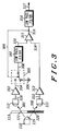
- FIG. 3 shows a block diagram of the sensor compensation system.
- light emitted by the emitter 110 passes through the disc 113 with part of the light passing through the grey scale track 120 printed on the circumference of the disc 113 and being directed at the measurement photodetector 111 and the other part of the light passes through the transparent track 121 and is incident on the reference photodetector 112.
- the amount of light 302 reaching the measurement photodetector 111 is: ⁇ .P LED .H( ⁇ ) and the amount of light 301 reaching the reference photodetector 112 is: ⁇ .P LED where ⁇ represents the environment attenuation between the emitter and the detectors.
- This attenuation is generally the same for the two detectors 111 and 112 because they are placed at the same distance from the emitter 110.
- This parameter can change with the environmental conditions, such as temperature, dust, humidity, disc ageing, etc., but the two detectors are always affected by the same amount of degradation.
- the photodetectors 111 and 112 each produce an electrical signal representing the amount of light incident on the detectors.
- a signal 318 from the reference detector 112 is equal to: ⁇ 1 . ⁇ .P LED and a signal 312 from the measurement photodetector 111 is equal to: ⁇ 2 . ⁇ .P LED .H( ⁇ ) where ⁇ 1 and ⁇ 2 represent the photon to electron conversion efficiency of the detectors.
- ⁇ 1 and ⁇ 2 can be different for each detector, but each one varies in the same proportion with the temperature, so the effect of this variation on the output signal is relatively small. Amplification is then needed to provide a usable electrical signal.
- the factor H( ⁇ ) induces electrical signal variations with the angle of rotation which is what is required, but the factor A 2 . ⁇ 2 . ⁇ .P LED can also vary, especially with temperature, disc ageing and dust variations. Such variations can induce large variations in V sig even while the disc is not moving. This phenomenon is not desirable.
- the principle of the signal degradation compensation is to produce a ratio between equation (2) and equation (1) so that this ratio can be simplified by ⁇ .P LED , which represents the most important source of signal degradation, since the optical power output of a gallium arsenide infrared light emitting diode is highly temperature dependent.
- a comparator 311 is used to compare V sig with a signal 310 called V cor .
- the comparator 311 is an operational amplifier used as a comparator, so one of its properties is that the difference between the inverting input and the non-inverting input is equal to zero (ideal operational amplifier).
- a chopper 305 is coupled with its output switching periodically between the output of the amplifier 303 and ground 306 so that the mean value after chopping is lower or equal to V ref .
- a low pass filter 307 is used, which averages the chopper output signal 308.
- a feedback loop 309 is used to drive the chopper.
- V cor > V sig
- the comparator 311 output signal 315 will go low and, via the feedback loop 309, will switch the chopper 305 to ground 306 so that the chopper output signal 308 falls to zero.
- the filter output signal 310 will decrease until V cor ⁇ V sig .
- x represents the duty cycle of the signal used to drive the chopper 305.
- the signal used to drive the chopper 305 is the output signal 315 coming from the comparator 311.
- FIG. 4 shows a particular arrangement of the circuit elements described with reference to FIG. 3.
- Three terminals 408, 409, and 410 are connected to the integrated connector 106, and provide the power supply, the ground, and the output signal, respectively.
- Emitter 110 connected between the power supply and the ground, is composed of an infrared Light Emitting Diode (LED) 412, such as a MLED930 in a metal can TO18 OPTO housing and a current limitation surface mount resistor 413.
- LED Light Emitting Diode
- the LED 412 illuminates the two detectors 112 and 111 as described above.
- the reference detector 402 is composed of a PIN photodiode 418, such as a MRD500 in a metal can TO18 OPTO housing, and an operational amplifier 420, such as the MC33202D in an SO8 surface mount package, used as a current to voltage converter.
- a feedback surface mount resistor 419 provides the current to voltage conversion ratio.
- the measurement detector 403 is composed of a PIN photodiode 415, such as a MRD500 in a metal can TO18 OPTO housing, and an operational amplifier 414, such as the MC33202D in an SO8 surface mount package, used as a current to voltage converter.
- Two feedback surface mount resistors 416 and 417 provide the current to voltage conversion ratio.
- Resistor 416 is a fixed value resistor and resistor 417 is a calibration resistor which must be adjusted to obtain the same level of signal at the output of amplifier 414 as at the output of amplifier 420, as described above, when the two detectors are illuminated under the same conditions. This calibration is necessary to adjust the output signal full span to its maximum value.
- PIN diodes are preferable as they have good linearity and efficient photon to electron conversion.
- the chopper 305 is composed of a pair of complementary surface mount MOSFET transistors 424 and 423.
- Transistor 424 is a P-channel enhancement mode TMOS MOSFET, such as the MMBF0202P in a SOT23 package
- transistor 423 is an N-channel enhancement mode TMOS MOSFET, such as the MMBF0201N in a SOT23 package.
- TMOS MOSFET P-channel enhancement mode MOSFET
- R DS(on) low drain - source on resistance
- the first low pass filter 307 used to average the signal coming from the chopper 305 is a first order filter composed of a surface mount resistor 422 and a surface mount capacitor 421.
- the comparator 311 is composed of two operational amplifier 425 and 426, such as the MC33202D in a SO8 surface mount package, used in a comparator configuration.
- the first operational amplifier 425 compares the measurement signal coming from the measurement detector 403 with the corrected voltage coming from the low pass filter 307.
- the second operational amplifier 426 is used to slow down the state changes from the operational amplifier 425 to an acceptable value compared to the operational amplifier slew rate.
- the operational amplifier 426 used as a comparator with hysteresis is dedicated to this function. Good switching characteristics are obtained with the switching limits set at 0.25.Vcc and 0.75.Vcc. Surface mount resistors 427, 428 and 429 are used to set these switching points.
- the output of the comparator 311 drives the chopper 305 and the output filter 316.
- the output filter 316 is a second order Sallen-Key low pass filter used to average the digital signal from the comparator 311.
- the second order active filter provide stronger filtering and also a low output impedance compared to a typical R-C filter.
- the mean value of the signal output from the comparator 311 is proportional to the input angle of rotation as described hereinabove.
- the output filter 316 is composed of a "rail to rail" operational amplifier 434, such as MC33202D in a SO8 surface mount package, for maximum amplitude, two resistors 430 and 431, and two capacitors 432 and 433.
- a cut-off frequency of between 650 and 1000 Hz, the averaging of the digital signal output from the comparator 311 with a frequency in the range of 15 Khz is efficient and maintains a fast response time of the system ( ⁇ 10 ms).
- the output signal from terminal 410 can thus be used directly by an electronic control unit (not shown).
Landscapes
- Physics & Mathematics (AREA)
- General Physics & Mathematics (AREA)
- Optical Transform (AREA)
- Length Measuring Devices By Optical Means (AREA)
Applications Claiming Priority (2)
| Application Number | Priority Date | Filing Date | Title |
|---|---|---|---|
| FR9506902 | 1995-06-12 | ||
| FR9506902A FR2735225B1 (fr) | 1995-06-12 | 1995-06-12 | Capteur de position optoelectronique et systeme de compensation pour un tel capteur |
Publications (1)
| Publication Number | Publication Date |
|---|---|
| EP0749003A1 true EP0749003A1 (fr) | 1996-12-18 |
Family
ID=9479851
Family Applications (1)
| Application Number | Title | Priority Date | Filing Date |
|---|---|---|---|
| EP96108833A Withdrawn EP0749003A1 (fr) | 1995-06-12 | 1996-06-03 | Capteurs opto-électronique et système de compensation |
Country Status (4)
| Country | Link |
|---|---|
| US (1) | US5773820A (fr) |
| EP (1) | EP0749003A1 (fr) |
| JP (1) | JPH09105645A (fr) |
| FR (1) | FR2735225B1 (fr) |
Cited By (2)
| Publication number | Priority date | Publication date | Assignee | Title |
|---|---|---|---|---|
| EP0997707A1 (fr) * | 1998-10-26 | 2000-05-03 | Eaton Corporation | Capteur de position rotative |
| WO2002040945A1 (fr) * | 2000-11-15 | 2002-05-23 | Leopold Kostal Gmbh & Co. Kg | Procede d"interpretation de signaux issus d"un dispositif optoelectronique de mesure de trajectoire et d"angle, et mise en oeuvre d"un procede de ce type |
Families Citing this family (77)
| Publication number | Priority date | Publication date | Assignee | Title |
|---|---|---|---|---|
| US5540108A (en) * | 1994-02-25 | 1996-07-30 | Advanced Mechanical Technology, Inc. | Multi-axis wheel transducer with angular position detector |
| US5903000A (en) * | 1997-03-31 | 1999-05-11 | Honeywell Inc. | Method for determining the position of a rotating shaft |
| US5828060A (en) * | 1997-03-31 | 1998-10-27 | Honeywell Inc. | Apparatus for determining the position of a rotating shaft |
| US6538555B2 (en) * | 1998-03-13 | 2003-03-25 | Mannesmann Vdo Ag | Throttle valve having potentiometer with supporting plate |
| JPH11351912A (ja) * | 1998-06-05 | 1999-12-24 | Yaskawa Electric Corp | 光学式エンコーダ |
| US6177997B1 (en) * | 1998-08-19 | 2001-01-23 | The United States Of America As Represented By The Administrator Of The National Aeronautics And Space Administration | Shaft position optical sensor |
| DE19951340C2 (de) * | 1999-10-25 | 2002-07-18 | Freudenberg Carl Kg | Dichtungsanordnung |
| US6580352B1 (en) | 1999-11-19 | 2003-06-17 | Aptek William, Inc. | Manual control apparatus and method |
| US6622589B1 (en) | 1999-11-19 | 2003-09-23 | Aptek Williams, Inc. | Manual control apparatus |
| US6594225B1 (en) * | 2000-03-01 | 2003-07-15 | Funai Electric Co., Ltd. | Disk rotation monitoring mechanism with parallel sensor unit |
| DE10056605A1 (de) | 2000-11-15 | 2002-05-23 | Kostal Leopold Gmbh & Co Kg | Verfahren zur Signalauswertung einer optoelektronischen Weg-oder Winkelmeßeinrichtung sowie Verwendung eines solchen Verfahrens |
| US7390689B2 (en) * | 2001-05-25 | 2008-06-24 | President And Fellows Of Harvard College | Systems and methods for light absorption and field emission using microstructured silicon |
| US7442629B2 (en) | 2004-09-24 | 2008-10-28 | President & Fellows Of Harvard College | Femtosecond laser-induced formation of submicrometer spikes on a semiconductor substrate |
| US7354792B2 (en) * | 2001-05-25 | 2008-04-08 | President And Fellows Of Harvard College | Manufacture of silicon-based devices having disordered sulfur-doped surface layers |
| US7057256B2 (en) | 2001-05-25 | 2006-06-06 | President & Fellows Of Harvard College | Silicon-based visible and near-infrared optoelectric devices |
| JP4601439B2 (ja) * | 2005-02-01 | 2010-12-22 | 株式会社日立ハイテクノロジーズ | プラズマ処理装置 |
| US20060187573A1 (en) * | 2005-02-24 | 2006-08-24 | Electro-Sensors, Inc. | Sensor equipment guard |
| US8107812B2 (en) * | 2005-09-23 | 2012-01-31 | Honeywell International Inc. | Dynamic range measurement and calculation of optical keyless entry sensor |
| WO2007125536A1 (fr) * | 2006-04-27 | 2007-11-08 | Vetrivel Prabhu M | Lecteur de cadran électronique |
| JP2008064547A (ja) * | 2006-09-06 | 2008-03-21 | Sharp Corp | 光学式エンコーダ |
| US8603902B2 (en) * | 2008-01-31 | 2013-12-10 | President And Fellows Of Harvard College | Engineering flat surfaces on materials doped via pulsed laser irradiation |
| US8058615B2 (en) * | 2008-02-29 | 2011-11-15 | Sionyx, Inc. | Wide spectral range hybrid image detector |
| US20090219403A1 (en) * | 2008-02-29 | 2009-09-03 | Sionyx, Inc. | Compact passive low-light imaging apparatus |
| WO2009111327A2 (fr) * | 2008-02-29 | 2009-09-11 | Sionyx, Inc. | Capteur de lumière intégré verticalement et matrices |
| US8212327B2 (en) * | 2008-03-06 | 2012-07-03 | Sionyx, Inc. | High fill-factor laser-treated semiconductor device on bulk material with single side contact scheme |
| WO2009128855A1 (fr) | 2008-04-17 | 2009-10-22 | Sionyx, Inc. | Piège à ions formé par traitement au laser et procédés de fabrication |
| US20100013036A1 (en) * | 2008-07-16 | 2010-01-21 | Carey James E | Thin Sacrificial Masking Films for Protecting Semiconductors From Pulsed Laser Process |
| WO2010019161A1 (fr) * | 2008-08-15 | 2010-02-18 | Sionyx, Inc. | Détecteur de lumière semi-conducteur à large bande |
| US8679959B2 (en) * | 2008-09-03 | 2014-03-25 | Sionyx, Inc. | High sensitivity photodetectors, imaging arrays, and high efficiency photovoltaic devices produced using ion implantation and femtosecond laser irradiation |
| US7968834B2 (en) * | 2008-09-22 | 2011-06-28 | Sionyx, Inc. | Response-enhanced monolithic-hybrid pixel |
| US20100090347A1 (en) * | 2008-10-09 | 2010-04-15 | Saylor Stephen D | Apparatus and method for contact formation in semiconductor devices |
| US7608813B1 (en) | 2008-11-18 | 2009-10-27 | Mitutoyo Corporation | Scale track configuration for absolute optical encoder including a detector electronics with plurality of track detector portions |
| US20100147383A1 (en) * | 2008-12-17 | 2010-06-17 | Carey James E | Method and apparatus for laser-processing a semiconductor photovoltaic apparatus |
| US7745901B1 (en) * | 2009-01-29 | 2010-06-29 | Sionyx, Inc. | Highly-depleted laser doped semiconductor volume |
| US20100210930A1 (en) * | 2009-02-13 | 2010-08-19 | Saylor Stephen D | Physiological Blood Gas Detection Apparatus and Method |
| US7928355B2 (en) * | 2009-02-25 | 2011-04-19 | Sionyx, Inc. | Current subtraction pixel |
| US20100224229A1 (en) * | 2009-03-09 | 2010-09-09 | Pralle Martin U | Multi-junction semiconductor photovoltaic apparatus and methods |
| US8207051B2 (en) * | 2009-04-28 | 2012-06-26 | Sionyx, Inc. | Semiconductor surface modification |
| US8094323B2 (en) | 2009-06-26 | 2012-01-10 | Mitutoyo Corporation | Displacement encoder including phosphor illumination source |
| US9673243B2 (en) | 2009-09-17 | 2017-06-06 | Sionyx, Llc | Photosensitive imaging devices and associated methods |
| US9911781B2 (en) | 2009-09-17 | 2018-03-06 | Sionyx, Llc | Photosensitive imaging devices and associated methods |
| JP5961332B2 (ja) * | 2009-09-17 | 2016-08-02 | サイオニクス、エルエルシー | 感光撮像素子および関連方法 |
| US8692198B2 (en) | 2010-04-21 | 2014-04-08 | Sionyx, Inc. | Photosensitive imaging devices and associated methods |
| US8309906B2 (en) | 2010-06-10 | 2012-11-13 | Mitutoyo Corporation | Absolute optical encoder with long range intensity modulation on scale |
| WO2011160130A2 (fr) | 2010-06-18 | 2011-12-22 | Sionyx, Inc | Dispositifs photosensibles à grande vitesse et procédés associés |
| US9091569B2 (en) | 2011-04-19 | 2015-07-28 | Caterpillar Inc. | Opacity-based rotary position sensor and method |
| US20120280127A1 (en) * | 2011-05-06 | 2012-11-08 | GM Global Technology Operations LLC | Two color spread spectrum optical encoder |
| US9496308B2 (en) | 2011-06-09 | 2016-11-15 | Sionyx, Llc | Process module for increasing the response of backside illuminated photosensitive imagers and associated methods |
| US20130016203A1 (en) | 2011-07-13 | 2013-01-17 | Saylor Stephen D | Biometric imaging devices and associated methods |
| US8941052B2 (en) | 2011-12-23 | 2015-01-27 | Mitutoyo Corporation | Illumination portion for an adaptable resolution optical encoder |
| US9080899B2 (en) | 2011-12-23 | 2015-07-14 | Mitutoyo Corporation | Optical displacement encoder having plural scale grating portions with spatial phase offset of scale pitch |
| US9029757B2 (en) | 2011-12-23 | 2015-05-12 | Mitutoyo Corporation | Illumination portion for an adaptable resolution optical encoder |
| US9018578B2 (en) | 2011-12-23 | 2015-04-28 | Mitutoyo Corporation | Adaptable resolution optical encoder having structured illumination and spatial filtering |
| US9064764B2 (en) | 2012-03-22 | 2015-06-23 | Sionyx, Inc. | Pixel isolation elements, devices, and associated methods |
| EP2743650B1 (fr) | 2012-12-17 | 2017-05-31 | Mitutoyo Corporation | Partie d'éclairage pour un codeur optique à résolution adaptable |
| JP2014119446A (ja) | 2012-12-17 | 2014-06-30 | Mitsutoyo Corp | 光学エンコーダ用の照明部 |
| JP6466346B2 (ja) | 2013-02-15 | 2019-02-06 | サイオニクス、エルエルシー | アンチブルーミング特性を有するハイダイナミックレンジcmos画像センサおよび関連づけられた方法 |
| WO2014151093A1 (fr) | 2013-03-15 | 2014-09-25 | Sionyx, Inc. | Imagerie tridimensionnelle utilisant des dispositifs imageurs empilés et procédés associés |
| JP5821109B2 (ja) * | 2013-06-17 | 2015-11-24 | 株式会社安川電機 | エンコーダ付きモータ |
| WO2014209421A1 (fr) | 2013-06-29 | 2014-12-31 | Sionyx, Inc. | Régions texturées formées de tranchées peu profondes et procédés associés. |
| DE102015209716B4 (de) | 2014-05-29 | 2023-04-20 | Mitutoyo Corporation | Optischer Codierer mit anpassbarer Auflösung |
| US9267819B2 (en) | 2014-06-12 | 2016-02-23 | Mitutoyo Corporation | Absolute position encoder scale having plates alternating with varying recesses |
| US9435663B2 (en) | 2014-08-22 | 2016-09-06 | Mitutoyo Corporation | Absolute position encoder scale having layers in a stacked configuration |
| US9612136B1 (en) | 2015-09-30 | 2017-04-04 | Mitutoyo Corporation | Absolute position encoder including a redundant spatial phase signal |
| US9958294B2 (en) | 2016-06-30 | 2018-05-01 | Mitutoyo Corporation | Absolute position encoder including scale with varying spatial characteristic and utilizing Fourier transform or other signal processing |
| US9772202B1 (en) | 2016-07-01 | 2017-09-26 | Mitutoyo Corporation | Absolute position encoder combining signals of two widely separated wavelengths |
| US10422666B2 (en) | 2016-12-23 | 2019-09-24 | Mitutoyo Corporation | Electronic position encoder and method for reducing short range errors |
| US10168189B1 (en) | 2017-06-29 | 2019-01-01 | Mitutoyo Corporation | Contamination and defect resistant optical encoder configuration for providing displacement signal having a plurality of spatial phase detectors arranged in a spatial phase sequence along a direction transverse to the measuring axis |
| US10295378B2 (en) | 2017-06-29 | 2019-05-21 | Mitutoyo Corporation | Contamination and defect resistant optical encoder configuration outputting structured illumination to a scale plane for providing displacement signals |
| US10295648B2 (en) | 2017-06-29 | 2019-05-21 | Mitutoyo Corporation | Contamination and defect resistant optical encoder configuration including a normal of readhead plane at a non-zero pitch angle relative to measuring axis for providing displacement signals |
| US10648838B2 (en) | 2017-06-29 | 2020-05-12 | Mitutoyo Corporation | Contamination and defect resistant rotary optical encoder configuration including a rotary scale with yawed scale grating bars and structured illumination generating arrangement with a beam deflector configuration |
| US10302466B2 (en) | 2017-06-29 | 2019-05-28 | Mitutoyo Corporation | Contamination and defect resistant optical encoder configuration including first and second illumination source diffraction gratings arranged in first and second parallel planes for providing displacement signals |
| US10724877B2 (en) | 2017-10-23 | 2020-07-28 | Mitutoyo Corporation | Compact pseudorandom scale and read head for an inductive type absolute position encoder |
| DE102018251727A1 (de) | 2017-12-29 | 2019-07-04 | Mitutoyo Corporation | Verschmutzungs- und defektbeständige optische Drehpositionsgeberkonfiguration zum Bereitstellen von Verschiebungssignalen |
| CN108279032B (zh) * | 2018-01-17 | 2023-09-15 | 歌尔科技有限公司 | 一种产品性能测试方法和系统 |
| JP2020056786A (ja) | 2018-09-28 | 2020-04-09 | 株式会社ミツトヨ | 光学式ロータリーエンコーダ |
| FR3126491B1 (fr) * | 2021-09-01 | 2023-07-21 | Codechamp | Dispositif de reglage d’un cœur optique a photodetecteurs et procede de reglage |
Citations (4)
| Publication number | Priority date | Publication date | Assignee | Title |
|---|---|---|---|---|
| JPS608714A (ja) * | 1983-06-29 | 1985-01-17 | Tamagawa Seiki Kk | 絶対位置検出形光学式シヤフトエンコ−ダ |
| WO1986000697A1 (fr) * | 1984-07-02 | 1986-01-30 | Societe Nationale Industrielle Aerospatiale | Procede et dispositif pour la determination de la position d'un organe mobile au moyen d'elements a proprietes optiques variables |
| EP0218308A2 (fr) * | 1983-01-29 | 1987-04-15 | Toyota Jidosha Kabushiki Kaisha | Appareil pour détecter la position angulaire et la vitesse angulaire d'un organe rotatif et méthode d'assemblage de l'appareil |
| JPH068714A (ja) * | 1992-04-02 | 1994-01-18 | Sumitomo Rubber Ind Ltd | 車両に装着されたタイヤの減圧検出方法 |
Family Cites Families (3)
| Publication number | Priority date | Publication date | Assignee | Title |
|---|---|---|---|---|
| US4109389A (en) * | 1976-03-08 | 1978-08-29 | Cetec Corporation | Shaft angle transducer |
| JPS5971598A (ja) * | 1982-10-18 | 1984-04-23 | フアナツク株式会社 | 光学式アブソリユ−トエンコ−ダ |
| US5376783A (en) * | 1992-09-16 | 1994-12-27 | Ophir Optronics Ltd. | Power meter with background subtraction |
-
1995
- 1995-06-12 FR FR9506902A patent/FR2735225B1/fr not_active Expired - Fee Related
-
1996
- 1996-05-29 US US08/656,997 patent/US5773820A/en not_active Expired - Fee Related
- 1996-06-03 EP EP96108833A patent/EP0749003A1/fr not_active Withdrawn
- 1996-06-11 JP JP8173022A patent/JPH09105645A/ja active Pending
Patent Citations (4)
| Publication number | Priority date | Publication date | Assignee | Title |
|---|---|---|---|---|
| EP0218308A2 (fr) * | 1983-01-29 | 1987-04-15 | Toyota Jidosha Kabushiki Kaisha | Appareil pour détecter la position angulaire et la vitesse angulaire d'un organe rotatif et méthode d'assemblage de l'appareil |
| JPS608714A (ja) * | 1983-06-29 | 1985-01-17 | Tamagawa Seiki Kk | 絶対位置検出形光学式シヤフトエンコ−ダ |
| WO1986000697A1 (fr) * | 1984-07-02 | 1986-01-30 | Societe Nationale Industrielle Aerospatiale | Procede et dispositif pour la determination de la position d'un organe mobile au moyen d'elements a proprietes optiques variables |
| JPH068714A (ja) * | 1992-04-02 | 1994-01-18 | Sumitomo Rubber Ind Ltd | 車両に装着されたタイヤの減圧検出方法 |
Non-Patent Citations (1)
| Title |
|---|
| PATENT ABSTRACTS OF JAPAN vol. 9, no. 122 (P - 359) 17 January 1985 (1985-01-17) * |
Cited By (3)
| Publication number | Priority date | Publication date | Assignee | Title |
|---|---|---|---|---|
| EP0997707A1 (fr) * | 1998-10-26 | 2000-05-03 | Eaton Corporation | Capteur de position rotative |
| US6194709B1 (en) | 1998-10-26 | 2001-02-27 | Eaton Corporation | Rotary position sensor/transducer employing rotor having color filtering |
| WO2002040945A1 (fr) * | 2000-11-15 | 2002-05-23 | Leopold Kostal Gmbh & Co. Kg | Procede d"interpretation de signaux issus d"un dispositif optoelectronique de mesure de trajectoire et d"angle, et mise en oeuvre d"un procede de ce type |
Also Published As
| Publication number | Publication date |
|---|---|
| JPH09105645A (ja) | 1997-04-22 |
| FR2735225B1 (fr) | 1997-09-05 |
| US5773820A (en) | 1998-06-30 |
| FR2735225A1 (fr) | 1996-12-13 |
Similar Documents
| Publication | Publication Date | Title |
|---|---|---|
| US5773820A (en) | Rotary position sensor with reference and grey scales | |
| US5410145A (en) | Light detector using reverse biased photodiodes with dark current compensation | |
| CA1102898A (fr) | Circuit compensateur d'eclairage ambiant | |
| US4070572A (en) | Linear signal isolator and calibration circuit for electronic current transformer | |
| US5270645A (en) | Linear-output, temperature-stable rotational sensor including magnetic field responsive device disposed within a cavity of a flux concentrator | |
| US5015836A (en) | Source intensity adjustment apparatus for optical channel | |
| US4502334A (en) | Combined pressure gauge-transmitter | |
| US6586719B1 (en) | Device for detecting the positional change between two bodies moving in relation to one another | |
| US4598586A (en) | Compensation of gain temperature coefficient in an optical pick-off for an accelerometer | |
| US4694157A (en) | Temperature compensated electro-optical light transmission circuit for use in a position detector | |
| US6107620A (en) | Photosensor using side surface light | |
| HK1044039B (zh) | 具有集成信号处理的传感器模块 | |
| US5977533A (en) | Pulse width modulated optical sensor interface circuit having an emitter control circuit | |
| CN112770437A (zh) | 一种标准光源 | |
| WO1994000742A1 (fr) | Mesure de lumiere | |
| US4080074A (en) | Automatic zeroing circuit to compensate for dark currents or the like | |
| JPH04268816A (ja) | 物体検出用光電スイッチ | |
| GB2151774A (en) | Measuring displacement | |
| JPH06100648B2 (ja) | 反射型ホトインタラプタ | |
| JPH0453589Y2 (fr) | ||
| JPH05172606A (ja) | 熱式流量計 | |
| KR20000073184A (ko) | 연소제어장치를 갖는 보일러 | |
| RU2122185C1 (ru) | Способ измерений потока излучения | |
| RU2073200C1 (ru) | Оптико-электронное измерительное устройство | |
| JPS60140117A (ja) | 角度センサ |
Legal Events
| Date | Code | Title | Description |
|---|---|---|---|
| PUAI | Public reference made under article 153(3) epc to a published international application that has entered the european phase |
Free format text: ORIGINAL CODE: 0009012 |
|
| AK | Designated contracting states |
Kind code of ref document: A1 Designated state(s): DE GB IT |
|
| 17P | Request for examination filed |
Effective date: 19970618 |
|
| 17Q | First examination report despatched |
Effective date: 19990203 |
|
| RTI1 | Title (correction) |
Free format text: COMPENSATION SYSTEM FOR AN OPTOELECTRONIC SENSOR |
|
| GRAG | Despatch of communication of intention to grant |
Free format text: ORIGINAL CODE: EPIDOS AGRA |
|
| GRAG | Despatch of communication of intention to grant |
Free format text: ORIGINAL CODE: EPIDOS AGRA |
|
| GRAH | Despatch of communication of intention to grant a patent |
Free format text: ORIGINAL CODE: EPIDOS IGRA |
|
| STAA | Information on the status of an ep patent application or granted ep patent |
Free format text: STATUS: THE APPLICATION IS DEEMED TO BE WITHDRAWN |
|
| 18D | Application deemed to be withdrawn |
Effective date: 20010630 |