EP0218315A2 - Siebklemmvorichtung - Google Patents
Siebklemmvorichtung Download PDFInfo
- Publication number
- EP0218315A2 EP0218315A2 EP86304423A EP86304423A EP0218315A2 EP 0218315 A2 EP0218315 A2 EP 0218315A2 EP 86304423 A EP86304423 A EP 86304423A EP 86304423 A EP86304423 A EP 86304423A EP 0218315 A2 EP0218315 A2 EP 0218315A2
- Authority
- EP
- European Patent Office
- Prior art keywords
- screen
- screen member
- frame
- basket
- inflatable
- Prior art date
- Legal status (The legal status is an assumption and is not a legal conclusion. Google has not performed a legal analysis and makes no representation as to the accuracy of the status listed.)
- Ceased
Links
- 238000012216 screening Methods 0.000 claims abstract description 20
- 239000012530 fluid Substances 0.000 claims abstract description 18
- 238000000034 method Methods 0.000 claims description 9
- 239000007788 liquid Substances 0.000 description 4
- 238000013022 venting Methods 0.000 description 4
- 229910000831 Steel Inorganic materials 0.000 description 3
- 239000010720 hydraulic oil Substances 0.000 description 3
- 238000003780 insertion Methods 0.000 description 3
- 230000037431 insertion Effects 0.000 description 3
- 239000010959 steel Substances 0.000 description 3
- 238000004140 cleaning Methods 0.000 description 2
- 239000000463 material Substances 0.000 description 2
- 239000003921 oil Substances 0.000 description 2
- 230000002093 peripheral effect Effects 0.000 description 2
- 238000013461 design Methods 0.000 description 1
- 238000005553 drilling Methods 0.000 description 1
- 230000000694 effects Effects 0.000 description 1
- 239000003129 oil well Substances 0.000 description 1
- 239000012858 resilient material Substances 0.000 description 1
- 239000007787 solid Substances 0.000 description 1
- 238000005728 strengthening Methods 0.000 description 1
Images


Classifications
-
- B—PERFORMING OPERATIONS; TRANSPORTING
- B07—SEPARATING SOLIDS FROM SOLIDS; SORTING
- B07B—SEPARATING SOLIDS FROM SOLIDS BY SIEVING, SCREENING, SIFTING OR BY USING GAS CURRENTS; SEPARATING BY OTHER DRY METHODS APPLICABLE TO BULK MATERIAL, e.g. LOOSE ARTICLES FIT TO BE HANDLED LIKE BULK MATERIAL
- B07B1/00—Sieving, screening, sifting, or sorting solid materials using networks, gratings, grids, or the like
- B07B1/46—Constructional details of screens in general; Cleaning or heating of screens
- B07B1/48—Stretching devices for screens
Definitions
- This invention concerns the mounting of screens in vibratory apparatus such as is used for the sifting of mud and the like materials derived from oil-well drilling.
- a clamping device for a screen member in vibratory screening apparatus comprising a frame member and inflatable means on the frame member, whereby the device can be inserted into said apparatus to overlie at least a part of a screen member and the inflatable means can be inflated to press against a part of the screen member so as to clamp the screen member in position in the apparatus.
- a method of clamping a screen member in vibratory screening apparatus in which a clamping device comprising a frame member and inflatable means on the frame member is inserted into the apparatus to overlie at least a part of the screen member and the inflatable means is inflated to press against a part of the screen member so as to clamp the screen member in position in the apparatus.
- the clamping device may be arranged to be inserted either above or below the screen member.
- the inflatable means comprises at least one inflatable member located around the periphery of the frame member.
- the inflatable means may also comprise a portion located within the area defined by the frame member and spaced from its periphery.
- the inflatable member ovelies at least part of the edge region of the screen member.
- the screen member may or may not include a screen frame in which the actual screen is located.
- a screen member comprising a screen in a frame will be used and the clamping device and the screen member are designed or selected relative to each other so that the inflatable means of the clamping device presses against the screen frame and not the screen itself.
- the screen member and the clamping device will be mounted in a basket of the vibratory screening apparatus and the inflatable means will press the screen member against part of the basket.
- the frame member of the clamping device will be referred to as an intermediate frame member, for distinction over the screen frame.
- the screen may be insertable into the apparatus untensioned, and may be tensioned subsequently (post-tensioning) against the body of the vibratory apparatus.
- the screen may be tensioned against the screen frame, and this may take the form of pre-tensioning the screen against the screen frame before insertion into the vibratory apparatus.
- Embodiments of the present invention may be used with pre-tensioned screens or post-tensioned screens.
- Our earlier applications GB-A-2161715 and GB-A-2162091 disclose permanently pre-tensioned screens with which embodiments of the present invention may be used.
- the inflatable member may for example be in the form of an elastomeric stocking which is secured to edge regions of the intermediate frame member so that when inflated and enlarged the increased cross-section of the stocking squezes firmly against one surface of the screen or the frame surrounding the screen and clamps it securely in position against the peripheral regions of the supporting structure. In this way the screen and/or its bounding frame is/are sandwiched between the basket on the one hand and the intermediate frame member on the other.
- the stocking extends around at least three sides of the intermediate frame member and preferably also the fourth side.
- the means for inflating the stocking or other device may be mounted on and form an integral part of the overall apparatus or a pressurized fluid or an airline connection may be provided on the stocking or on its associated intermediate frame member to enable the stocking to be inflated from a separate air supply or hydraulic fluid supply.
- a venting device by which the pressure in the stocking can be relieved.
- the inflating fluid is a hydraulic oil or other liquid
- the venting device preferably communicates with a reservoir of the liquid so that as the latter is exhausted from the stocking the oil can be returned to a common reservoir and is thereby saved.
- vibratory screening apparatus in which a screen member may be mounted, the apparatus having inflatable means located within it to overlie at least a part of a screen member mounted in the apparatus so that inflation of the inflatable means clamps the screen member in place.
- a method of clamping a screen member in place in a vibratory screening apparatus comprising inflatable means located within it to overlie at least a part of a screen member mounted in the apparatus, in which the inflatable means is inflated when the screen member is in place so as to clamp the screen member.
- the inflatable means may comprise one or more inflatable members.
- the inflatable means overlies at least a part of the edge region of the screen member.
- the screen member may or may not include a screen frame in which the actual screen is located. However, in normal use a screen member comprising a screen in a frame will be used and the screen member designed or selected so that the inflatable means of the vibratory screening apparatus acts on the screen frame and not on the screen itself.
- the inflatable means will be located within a basket of the vibratory screening apparatus in which basket the screen member may be mounted.
- the screen may be inserted into the apparatus untensioned, and be tensioned subsequently (post-tensioning) against the body of the vibratory apparatus.
- the screen may be tensioned against the screen frame, and this may take the form of pre-tensioning the screen against the screen frame before insertion into the vibratory apparatus.
- Embodiments of the present invention may be used with pre- tensioned screens or post-tensioned screens.
- Our earlier applications GB-A-2161715 and GB-A-2162091 disclose permanently pre-tensioned screens with which embodiments of the present invention may be used.
- the inflatable member may for example be in the form of an elastomeric stocking which is secured to edge regions of the screen member supporting structure of the vibratory apparatus so as to overlie the peripheral region of the screen member.
- the increased cross-section of the stocking pushes firmly against the upper (or lower) surface of the frame and screen and clamps it securely in position against the underside (or topside) supporting structure.
- the stocking extends around at least three sides of the frame and preferably also the fourth side.
- Means for inflating the stocking or other device may be mounted on and form an integral part of the overall apparatus or a pressurized fluid or airline connection may be provided on the stocking or connected to the stocking so as to enable the latter to be inflated from a separate air supply or hydraulic fluid supply.
- a venting device by which the pressure in the stocking can be relieved.
- the inflating fluid is a hydraulic oil or other liquid
- the venting device preferably communicates with a reservoir of the liquid so that as the latter is exhausted from the stocking the oil can be returned to a common reservoir and is thereby saved.
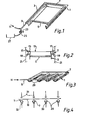
- a clamping device has an intermediate frame member 1 comprising an L-section portion 3 extending around three sides of a rectangle to form a U-shape, and a strut 5 across the mouth of the U to provide strength and rigidity.
- the frame member 1 is made of a relatively strong and rigid material such as steel.
- the L-section 3 carries an inflatable tube or stocking 7 on its upper surface.
- One end of the stocking 7 is extended to provide a supply line 9 by means of which inflation fluid may be introduced as indicated by arrow 11.
- the clamping device of Figure 1 is inserted together with a screen member, comprising a screen 13 mounted in a screen frame 15, between two lateral projections 17, 19 of a basket 21 of a vibratory screening machine.
- the screen member and the clamping device are arranged so that the screen frame 15 is opposed to the upper projection 17 of the basket and the L-section of the clamping device is opposed to the lower lateral projection 19 of the basket, with the inflatable stocking between the L-section 3 and the screen frame 15.
- the vertical spacing of members has been exaggerated in Figure 2 (and also in Figures 4 and 6).
- Inflation of the stocking 7 causes it to expand, so that it presses the screen frame 15 tightly against the upper projection 17 of the basket 21.
- the clamping device is prevented from moving downwardly away from the screen member by reaction between the L-section portion 3 and the lower projection 19 of the basket 21. In this manner, the screen member comprising the screen 13 and the screen frame 15 is clamped in position in the basket 21.
- pressurised fluid such as air or hydraulic fluid is provided through the supply line 9 as indicated by arrow 11.
- the supply line 9 also has a branch 23 leading to a pressure relief valve 25.
- Valve 25 is kept normally closed, and may be opened to allow deflation of the stocking 7. Deflation of the stocking 7 releases the clamping action on the screen frame 15, so that the screen member can be removed from the basket 21 for cleaning, replacement etc.
- the branch 23 in the supply line may be extended beyond the valve 25 to a reservoir, indicated schematically in Figure 1 at 27, where exhausted fluid may be collected.
- Figure 3 shows an alternative embodiment of the clamping device of the present invention.
- the intermediate frame member 1 is formed from a semi-circular section member 29, which again may be of steel.
- the inflatable stocking 7 lies within the concavity of the semi-circular section.
- the semi-circular sectioned portion 29 and the stocking 7 extend around three sides of a rectangle, as did the L-section portion 3 and the stocking 7 in Figure 1.
- the semi-circular section portion 29 and the stocking 7 have two longitudinal portions extending across the rectangle thus defined.
- the pressurised fluid supply line 9 extends along the fourth side of the rectangle and is connected to the stocking 7 at the ends of the adjacent two sides of the rectangle and the ends of the two portions extending across the rectangle.
- the supply line 9 is relatively rigid or is supported on a relatively rigid member at least where it forms the fourth side of the rectangle so as to increase the strength and rigidity of the clamping device as a whole.
- the clamping device of Figure 3 is intended to be used with a basket 21 which provides clamping support members 31, 33 for the screen member at intermediate positions across the width of the screen member.
- the screen 13 of the screen member may extend across the positions of these intermediate support members 31, 33, it is preferred that the screen frame 15 divides the screen 13 into separate regions, and portions of the screen frame 15 are provided in the positions opposed to the supporting members 31, 33.
- the clamping device of Figure 3 rests on the lower support members 33 of the basket 21, and the screen member is positioned between the stocking 7 of the clamping member and the upper support members 31.
- the lower ends of the upper support members 31, which will contact the screen member directly, are of a resilient material such as rubber.
- the clamping device of Figure 3 is used in a manner similar to the clamping device of Figure 1.
- the stocking 7 may be inflated to press the screen member against the upper support members 31, and the clamping device is itself supported by the lower support members 33.
- Figure 5 shows a third embodiment of the clamping device of the present invention.
- the intermediate frame member 1 comprises an E-shape formed from flat strip portions 35.
- the stocking 7 is bonded to the strip 35.
- the fluid supply line 9 is not shown in Figure 5 but may be provided in a manner similar to that of Figure 3.
- the basket 21 provides upper and lower lateral projections 17, 19 by means of which expansion of the inflatable stocking 7 clamps the screen member to the basket 21. Additionally, the basket 21 has upper and lower support members 31, 33 in a manner similar to the arrangement of Figure 4, midway between the two sides of the screen member, and the screen member has a portion of the screen frame 15 at this point, so that the middle arm of the E-shaped clamping device clamps the central portion of the screen member between the upper and lower support members 31, 33 of the basket 21.
- FIG. 7 shows a basket 101 of vibratory screening apparatus in which is located an expansible elastomeric member 103.
- a removable screen member comprising a screen 105 and a screen frame 107 is mounted within the basket 101 and supported by lateral projections 109 of the basket.
- the lateral projections 109 support the screen member immediately below the elastomeric member 103.
- the elastomeric member is secured to the basket at its upper side, so that inflation of the elastomeric member causes it to expand downwardly and press the screen member against the lateral projections 109 so as to hold the screen member firmly in place in the basket 101.
- the vertical spacing between members has been exaggerated in Figure 7 (and also in Figure 8) for clarity.
- the elastomeric member 103 extends around the periphery only of the area defined by the basket 101.
- the screen frame 107 forms the periphery of the screen member, and when the elastomeric member 103 is inflated it presses against the screen frame 107 only, and does not contact the screen 105.
- a supply line 111 is provided in order to convey pressurised air, hydraulic oil or other suitable medium, to the elastomeric member 103, as indicated by the arrow 113, in order to inflate it.
- the supply line 111 has a branch 115 leading to a pressure relief valve 117, whereby the inflation pressure in the inflatable member may be relieved and the member may be deflated. This releases the clamping effect on the screen member, so that it may be removed for replacement or cleaning.
- the branch line 115 is shown in Figure 7 to extend beyond the valve 117 to a reservoir 119 where vented inflation fluid may be collected.
- Figure 7 will be used with screens which are pre-tensioned against their screen frames.
- Figure 8 shows another embodiment of the present invention being used with a screen member in which the screen is tensioned after insertion into the basket.
- the screen frame 107 terminates in a turned back edge to form a hook strip 121.
- a tension rail 123 is attached to the side wall of the basket 101 by a tension bolt 125.
- the hook strip 121 is hooked around a part of the tension rail 123 when the screen member is inserted into the basket, and tightening of the tension bolt 125 moves the tension rail outwardly towards the side wall 101 of the basket so as to tension the screen member.
- the basket 101 also has steel support members 127, 129 extending across the screen member. Normally, the screen member will be selected so that portions of the screen frame 107 are opposed to these support members 127, 129, with strips of screen 105 in between.
- the lower support members 125 terminate in solid rubber end pieces 131.
- the upper support members 127 terminate in hollow rubber end pieces which form inflatable members 103.
- the inflatable members 103 are inflated. On inflation, the members 103 expand and press the screen member downwardly against the rubber end pieces 131. In this way, the screen member is held securely between the upper and lower supports 127, 129 of the basket 121.
- the inflatable members 103 do not only extend alongside the walls of the basket 101 but also extend across the area defined by those walls in positions spaced therefrom.
- Figure 9 shows a preferred hose design in which a flattened hose 132 is attached along a central linear region of its upper surface to the underside of a support member 134 and is held in place by a ring or the like 136.
- the latter may be elastic. The resilience of the ring 136 may help to deflate and flatten the hose 132 when the inflation fluid is vented.
- Figure 10 shows how a combination of two different types of expansible hose can be used to secure a screen in place.
- the generally square section hoses 138, 140 serve to grip the opposed edge regions of the screen frame and the intermediate hoses 142, 144 are positioned across the width of the screen to engage stiffening ribs or other strengthening means 146, which may be parts of the screen frame 107, located at intervals across the screen.
Landscapes
- Combined Means For Separation Of Solids (AREA)
- Supports Or Holders For Household Use (AREA)
Applications Claiming Priority (4)
| Application Number | Priority Date | Filing Date | Title |
|---|---|---|---|
| GB8514983 | 1985-06-13 | ||
| GB858514983A GB8514983D0 (en) | 1985-06-13 | 1985-06-13 | Screen clamping |
| GB858514982A GB8514982D0 (en) | 1985-06-13 | 1985-06-13 | Screen clamping |
| GB8514982 | 1985-06-13 |
Publications (2)
| Publication Number | Publication Date |
|---|---|
| EP0218315A2 true EP0218315A2 (de) | 1987-04-15 |
| EP0218315A3 EP0218315A3 (de) | 1988-05-11 |
Family
ID=26289367
Family Applications (1)
| Application Number | Title | Priority Date | Filing Date |
|---|---|---|---|
| EP86304423A Ceased EP0218315A3 (de) | 1985-06-13 | 1986-06-10 | Siebklemmvorichtung |
Country Status (5)
| Country | Link |
|---|---|
| EP (1) | EP0218315A3 (de) |
| AU (1) | AU583127B2 (de) |
| CA (1) | CA1304718C (de) |
| ES (1) | ES8706485A1 (de) |
| NO (1) | NO170199C (de) |
Cited By (6)
| Publication number | Priority date | Publication date | Assignee | Title |
|---|---|---|---|---|
| FR2631255A1 (fr) * | 1988-05-16 | 1989-11-17 | Szilvasi Peter | Cadres amovibles de cribles type cassette ou cartouche |
| GB2312858A (en) * | 1996-05-10 | 1997-11-12 | William Myron Cravello | Shaker screen assembly |
| GB2408006A (en) * | 2003-11-13 | 2005-05-18 | Russel Finex | Screen clamping mechanism |
| US6935511B2 (en) | 2002-10-17 | 2005-08-30 | Varco I/P, Inc. | Centrally supported screen assembly |
| WO2009046071A3 (en) * | 2007-10-05 | 2009-07-30 | Mi Llc | Screen clamp |
| US8245850B2 (en) | 2003-11-13 | 2012-08-21 | Russell Finex Limited | Screen separators |
Families Citing this family (1)
| Publication number | Priority date | Publication date | Assignee | Title |
|---|---|---|---|---|
| CN119406755A (zh) * | 2025-01-06 | 2025-02-11 | 四川远方云天食品科技有限公司 | 一种便于取料的火锅底料原料加工用多级筛选装置 |
Family Cites Families (7)
| Publication number | Priority date | Publication date | Assignee | Title |
|---|---|---|---|---|
| US2279042A (en) * | 1940-08-03 | 1942-04-07 | Inland Lime & Stone Company | Screening apparatus |
| FR1282627A (fr) * | 1960-12-13 | 1962-01-27 | Socam Sa | Dispositif pour le serrage de tamis |
| FR1326260A (fr) * | 1962-06-26 | 1963-05-03 | Dispositif pour tendre des tissus de tamisage et de filtrage | |
| AT329474B (de) * | 1974-02-25 | 1976-05-10 | Oesterr Amerikan Magnesit | Spannvorrichtung fur siebboden |
| US4082657A (en) * | 1976-01-19 | 1978-04-04 | Gage Ernest L | Separator apparatus |
| GB2085744B (en) * | 1980-10-20 | 1984-06-13 | Thule United Ltd | Vibratory screening apparatus |
| EP0130744A3 (de) * | 1983-07-01 | 1986-03-05 | Sweco, Inc. | Trennsieb und Verfahren zu seiner Herstellung |
-
1986
- 1986-06-04 NO NO862214A patent/NO170199C/no unknown
- 1986-06-10 ES ES555914A patent/ES8706485A1/es not_active Expired
- 1986-06-10 EP EP86304423A patent/EP0218315A3/de not_active Ceased
- 1986-06-11 AU AU58567/86A patent/AU583127B2/en not_active Expired
- 1986-06-12 CA CA000511418A patent/CA1304718C/en not_active Expired - Lifetime
Cited By (12)
| Publication number | Priority date | Publication date | Assignee | Title |
|---|---|---|---|---|
| FR2631255A1 (fr) * | 1988-05-16 | 1989-11-17 | Szilvasi Peter | Cadres amovibles de cribles type cassette ou cartouche |
| GB2312858A (en) * | 1996-05-10 | 1997-11-12 | William Myron Cravello | Shaker screen assembly |
| GB2312858B (en) * | 1996-05-10 | 2000-03-22 | William Myron Cravello | Shaker screen assembly |
| US6935511B2 (en) | 2002-10-17 | 2005-08-30 | Varco I/P, Inc. | Centrally supported screen assembly |
| GB2408006A (en) * | 2003-11-13 | 2005-05-18 | Russel Finex | Screen clamping mechanism |
| GB2408006B (en) * | 2003-11-13 | 2007-04-25 | Russel Finex | Improvements in screen separators |
| US7721896B2 (en) | 2003-11-13 | 2010-05-25 | Russell Finex Limited | Screen separators |
| US8245850B2 (en) | 2003-11-13 | 2012-08-21 | Russell Finex Limited | Screen separators |
| WO2009046071A3 (en) * | 2007-10-05 | 2009-07-30 | Mi Llc | Screen clamp |
| EA016036B1 (ru) * | 2007-10-05 | 2012-01-30 | Эм-Ай ЭлЭлСи | Зажим сита |
| US8561804B2 (en) | 2007-10-05 | 2013-10-22 | M-I Llc | Screen clamp |
| CN101821021B (zh) * | 2007-10-05 | 2015-12-16 | M-I有限公司 | 筛夹具 |
Also Published As
| Publication number | Publication date |
|---|---|
| NO862214L (no) | 1986-12-15 |
| AU583127B2 (en) | 1989-04-20 |
| NO170199B (no) | 1992-06-15 |
| ES555914A0 (es) | 1987-07-01 |
| AU5856786A (en) | 1986-12-18 |
| NO862214D0 (no) | 1986-06-04 |
| CA1304718C (en) | 1992-07-07 |
| NO170199C (no) | 1992-09-23 |
| ES8706485A1 (es) | 1987-07-01 |
| EP0218315A3 (de) | 1988-05-11 |
Similar Documents
| Publication | Publication Date | Title |
|---|---|---|
| US4744898A (en) | Inflatable screen clamp | |
| US4846352A (en) | Screen clamp | |
| US7850011B2 (en) | Screen system | |
| EP1711280B1 (de) | Vorrichtung zum trennen von feststoffen von einer feststoff enthaltenden bohrflüssigkeit und verfahren zum anbringen einer siebanordnung in einer vibrationstrennvorrichtung | |
| US3968033A (en) | Clamping device for screen bottoms | |
| EP0218315A2 (de) | Siebklemmvorichtung | |
| US7942272B2 (en) | Screen system | |
| US4816153A (en) | Frame member for pressurized screening device | |
| US6513665B1 (en) | Screen mounting system | |
| WO1997047404A1 (en) | Apparatus for attaching filter means to a frame | |
| DE69507687D1 (de) | Rakelklemmanordnung für eine druckmaschine | |
| US5355792A (en) | Two-part frame and pre-tensioning device therefor | |
| US5124037A (en) | Device for filtration of solid element contained within a liquid | |
| US3256992A (en) | Device for supporting sieves and filter materials | |
| JPH07505572A (ja) | スクリーンの取付け構造および張り構造 | |
| US4490076A (en) | Underground support devices | |
| EP0185409A2 (de) | Schüttelsieb | |
| JPH09502674A (ja) | 湾曲した支持体を固定する装置 | |
| CA2132785A1 (en) | Prop headboard | |
| JP4023605B2 (ja) | 2重空気膜パネル | |
| KR940000833Y1 (ko) | 용접용 진공 흡착 고정구 | |
| KR200161998Y1 (ko) | 자동차의 쇽 업소버 교체장치 | |
| EP0015950B1 (de) | Vorrichtung zum Spannen eines Stoffes in einem Rahmen zum Befestigen des Stoffes im gespannten Zustand am Rahmen | |
| JPH02282585A (ja) | 空気膜構造物の膜面振動防止方法 | |
| JP2005253863A (ja) | エアーマッサージ装置用エアーバッグ及びエアーマッサージ装置 |
Legal Events
| Date | Code | Title | Description |
|---|---|---|---|
| PUAI | Public reference made under article 153(3) epc to a published international application that has entered the european phase |
Free format text: ORIGINAL CODE: 0009012 |
|
| AK | Designated contracting states |
Kind code of ref document: A2 Designated state(s): FR IT NL |
|
| PUAL | Search report despatched |
Free format text: ORIGINAL CODE: 0009013 |
|
| AK | Designated contracting states |
Kind code of ref document: A3 Designated state(s): FR IT NL |
|
| 17P | Request for examination filed |
Effective date: 19881014 |
|
| 17Q | First examination report despatched |
Effective date: 19890906 |
|
| STAA | Information on the status of an ep patent application or granted ep patent |
Free format text: STATUS: THE APPLICATION HAS BEEN REFUSED |
|
| 18R | Application refused |
Effective date: 19911006 |
|
| RIN1 | Information on inventor provided before grant (corrected) |
Inventor name: BAILEY, MARSHALL GRAHAM |