EP0218367B1 - Fantôme pour analyse minérale d'os - Google Patents
Fantôme pour analyse minérale d'os Download PDFInfo
- Publication number
- EP0218367B1 EP0218367B1 EP86306795A EP86306795A EP0218367B1 EP 0218367 B1 EP0218367 B1 EP 0218367B1 EP 86306795 A EP86306795 A EP 86306795A EP 86306795 A EP86306795 A EP 86306795A EP 0218367 B1 EP0218367 B1 EP 0218367B1
- Authority
- EP
- European Patent Office
- Prior art keywords
- phantom
- bone mineral
- radiation
- housing
- cross sections
- Prior art date
- Legal status (The legal status is an assumption and is not a legal conclusion. Google has not performed a legal analysis and makes no representation as to the accuracy of the status listed.)
- Expired
Links
- 210000000988 bone and bone Anatomy 0.000 title claims description 67
- 229910052500 inorganic mineral Inorganic materials 0.000 title claims description 53
- 239000011707 mineral Substances 0.000 title claims description 53
- 230000005855 radiation Effects 0.000 claims description 58
- 210000001519 tissue Anatomy 0.000 claims description 32
- 238000012937 correction Methods 0.000 claims description 25
- 239000000463 material Substances 0.000 claims description 24
- 238000000034 method Methods 0.000 claims description 18
- 238000001514 detection method Methods 0.000 claims description 16
- 230000000149 penetrating effect Effects 0.000 claims description 12
- 230000001054 cortical effect Effects 0.000 claims description 4
- 239000012530 fluid Substances 0.000 claims description 2
- XLYOFNOQVPJJNP-UHFFFAOYSA-N water Substances O XLYOFNOQVPJJNP-UHFFFAOYSA-N 0.000 claims description 2
- 230000037182 bone density Effects 0.000 claims 1
- 210000004872 soft tissue Anatomy 0.000 description 4
- 230000000694 effects Effects 0.000 description 3
- 208000001132 Osteoporosis Diseases 0.000 description 2
- 230000004075 alteration Effects 0.000 description 2
- 238000004364 calculation method Methods 0.000 description 2
- 230000009977 dual effect Effects 0.000 description 2
- 230000002093 peripheral effect Effects 0.000 description 2
- 239000000126 substance Substances 0.000 description 2
- 238000012360 testing method Methods 0.000 description 2
- 238000010521 absorption reaction Methods 0.000 description 1
- 230000001154 acute effect Effects 0.000 description 1
- 210000000577 adipose tissue Anatomy 0.000 description 1
- 230000008859 change Effects 0.000 description 1
- 239000011248 coating agent Substances 0.000 description 1
- 238000000576 coating method Methods 0.000 description 1
- 238000002591 computed tomography Methods 0.000 description 1
- 239000013078 crystal Substances 0.000 description 1
- 238000003745 diagnosis Methods 0.000 description 1
- 238000002059 diagnostic imaging Methods 0.000 description 1
- 201000010099 disease Diseases 0.000 description 1
- 208000037265 diseases, disorders, signs and symptoms Diseases 0.000 description 1
- 230000005284 excitation Effects 0.000 description 1
- 230000006870 function Effects 0.000 description 1
- 238000003702 image correction Methods 0.000 description 1
- 238000003384 imaging method Methods 0.000 description 1
- 238000005259 measurement Methods 0.000 description 1
- 238000012544 monitoring process Methods 0.000 description 1
- 230000025508 response to water Effects 0.000 description 1
- 239000012056 semi-solid material Substances 0.000 description 1
- 239000011343 solid material Substances 0.000 description 1
- 230000007306 turnover Effects 0.000 description 1
Images

Classifications
-
- A—HUMAN NECESSITIES
- A61—MEDICAL OR VETERINARY SCIENCE; HYGIENE
- A61B—DIAGNOSIS; SURGERY; IDENTIFICATION
- A61B6/00—Apparatus or devices for radiation diagnosis; Apparatus or devices for radiation diagnosis combined with radiation therapy equipment
- A61B6/58—Testing, adjusting or calibrating thereof
- A61B6/582—Calibration
- A61B6/583—Calibration using calibration phantoms
-
- A—HUMAN NECESSITIES
- A61—MEDICAL OR VETERINARY SCIENCE; HYGIENE
- A61B—DIAGNOSIS; SURGERY; IDENTIFICATION
- A61B6/00—Apparatus or devices for radiation diagnosis; Apparatus or devices for radiation diagnosis combined with radiation therapy equipment
- A61B6/02—Arrangements for diagnosis sequentially in different planes; Stereoscopic radiation diagnosis
- A61B6/03—Computed tomography [CT]
- A61B6/032—Transmission computed tomography [CT]
-
- A—HUMAN NECESSITIES
- A61—MEDICAL OR VETERINARY SCIENCE; HYGIENE
- A61B—DIAGNOSIS; SURGERY; IDENTIFICATION
- A61B6/00—Apparatus or devices for radiation diagnosis; Apparatus or devices for radiation diagnosis combined with radiation therapy equipment
- A61B6/48—Diagnostic techniques
- A61B6/482—Diagnostic techniques involving multiple energy imaging
-
- H—ELECTRICITY
- H05—ELECTRIC TECHNIQUES NOT OTHERWISE PROVIDED FOR
- H05G—X-RAY TECHNIQUE
- H05G1/00—X-ray apparatus involving X-ray tubes; Circuits therefor
- H05G1/08—Electrical details
- H05G1/26—Measuring, controlling or protecting
-
- H—ELECTRICITY
- H05—ELECTRIC TECHNIQUES NOT OTHERWISE PROVIDED FOR
- H05G—X-RAY TECHNIQUE
- H05G1/00—X-ray apparatus involving X-ray tubes; Circuits therefor
- H05G1/08—Electrical details
- H05G1/60—Circuit arrangements for obtaining a series of X-ray photographs or for X-ray cinematography
Definitions
- This invention relates to the art of medical diagnostic imaging. More particularly this invention finds application in the calibration of tomographic scanners in conjunction with the diagnosis of osteoporosis and will be described with particular reference thereto. It is to be appreciated, however, that the invention may find further application in conjunction with other calibrations of tomographic scanners and other medical diagnostic equipment.
- Osteoporosis is a disease of long duration which is characterised by a bone mineral loss.
- the trabecular bone which has a turnover rate about eight times higher than cortical bone, has been shown to be a sensitive early indicator of bone mineral loss.
- One method of monitoring for bone mineral loss has been to examine the spine, which is approximately 65% trabecular bone with an x-ray tomographic scan.
- the x-ray absorption characteristics of the trabecular bone and the reconstructed image are indicative of bone mineral content or density of the trabecular bone.
- One of the problems which has been encountered with x-ray tomographic scans of the trabecular bone has been calibrating the CT numbers or gray scale of the resultant image with sufficient precision to measure the amount of mineral loss accurately or to detect small mineral losses.
- the accuracy of the mineral content is determined by the accuracy of the CT numbers for the selected scanner and the chemical composition of the imaged bone tissue. Because the density of fat is less than that of soft tissue, it reduces the measured CT number by about 12 Hounsfield units per 10% of fat by weight. This produces an erroneous decrease in the measured bone mineral concentration. Concentrations of fat in the vertebral body of up to 40% have been reported. To reduce the magnitude of the CT number alteration attributable to fat, dual energy CT scanning techniques have been used.
- the image reconstruction algorithms, x-ray spatial intensity compensation filters, x-ray beam filters, and x-ray beam hardness and scanner correction methods differ among various tomographic scanners.
- scanner performance has been optimized by the use of empirical corrections to the above parameters to provide a flat response to water or tissue equivalent phantoms.
- These empirical corrections in many instances, have not been linear to retain quantitative reconstructions over the entire field of view.
- These common, nonlinear quantitative corrections in many instances are not constant for all body dimensions and x-ray excitation conditions.
- the x-ray beam quality is different for rays emerging through the center and the periphery of large bodies as contrasted with small body sections. This beam quality difference results in variations of the CT numbers of identical bone mineral materials.
- the Volz bone mineral reference samples are disposed peripherally where they are irradiated by off-focal radiation which has not passed through the same volume of soft tissue as the radiation passing through the spine.
- the peripheral, off-focal radiation may also introduce additional errors attributable to less accurate corrections made by shaped x-ray filters and compensators to off-focal radiation.
- a tomographic scanner with bone mineral calibration, comprising: a source of penetrating radiation for providing at least one generally planar beam of penetrating radiation; a radiation detection means for detecting penetrating radiation impinging thereon; a gantry means for mounting the radiation source and the radiation detection means across an image region from each other such that the radiation beam traverses the image region and impinges on the radiation detection means; a bone mineral phantom; a phantom positioning means for positioning said phantom within said image region; a radiation moving means for moving at least the radiation beam relative to the phantom such that the radiation beam traversing the image region penetrates the phantom along a plurality of directions when said phantom is positioned within said image region; and an image reconstruction means for reconstructing a representation of material density in the image region from radiation detection data from the radiation detection means, the image reconstruction means being operatively connected with the radiation detection means and the radiation moving means characterised in that; said
- a phantom for calibrating CT scanners for bone mineral examinations characterised in that it comprises: a housing having a tapered side wall extending between a first end and a second end, the internal surface of the housing side wall defining a first, smaller area generally ovoid internal cross section adjacent the first end, a second, larger area generally ovoid internal cross section adjacent the second end and a plurality of intermediate internal cross sections of different areas which are larger than the first cross section and smaller than the second cross sections therebetween, thereby to provide between said first and second ends of the housing a plurality of transverse cross sections of different areas through tissue equivalent material contained in the housing; and a generally cylindrical bone mineral standard extending longitudinally generally between the first and second ends, whereby any one of the first, second, and intermediate internal cross sections are imageable in a tomographic scanner to provide a calibration reference.
- a method of tomographic scanning with bone mineral calibration comprising the steps of: (a) positioning a bone mineral phantom within a region of a tomographic scanner to be imaged; (b) rotating a source of penetrating radiation to irradiate the phantom from a plurality of directions; (c) detecting radiation which has traversed the phantom; (d) reconstructing an image representation from the detected penetrating radiation; (e) storing information from the phantom image representation; (f) repeating preceding steps (a) to (e) wherein instead of said phantom a mid-portion of a patient is disposed in the image region to reconstruct an image representation of a planar slice through the patient's mid-section; and (g) calibrating the patient image representation with the phantom image representation information characterised in that: there is used a bone mineral phantom comprising a generally cylindrical bone mineral calibration standard which extends longitudinally through said phantom
- US-A 4 055 771 discloses test bodies for determining an operating characteristic of a tomographic apparatus contained in housings whose external surfaces are tapered.
- none of the actual test bodies described in US-A 4 055 771 comprises a bone mineral phantom extending through tissue equivalent material whose cross-sectional area differs along the length of the bone mineral phantom.
- the phantom includes a tissue equivalent portion A and a bone mineral equivalent portion B.
- the tissue equivalent portion has a first end 10 which has a first or smaller generally ovoid cross section.
- the first end is shaped in conformity with the cross section of a smaller or skin- nier patient's mid-section adjacent the L2 to L5 vertebrae.
- the tissue equivalent portion A further has a second end 12 which has a second or larger generally ovoid cross section.
- the second cross section conforms to the shape of a larger or fatter patient adjacent the L2 to L5 vertebrae.
- a central portion 14 of the tissue equivalent structure has a plurality of intermediate cross sections which are larger than the first or smaller cross section and smaller than the second or larger cross section.
- the intermediate cross sections are arranged in a continuum.
- discrete cross sections may be provided.
- a plurality of markings 16 provide a means for indicating the transverse cross section at discrete intervals along the central portion 14 .
- the tissue equivalent portion includes an outer, hollow housing 20 which has an access aperture 22 therethrough to enable the interior to be filled with water or other tissue equivalent fluids.
- the tissue equivalent portion could be constructed of or filled with a tissue equivalent plastic or other solid or semi-solid material.
- the bone mineral equivalent portion B in the preferred embodiment is a cylindrical bone mineral calibration standard 30 of a bone mineral tissue mimicking substance.
- the standard has a tubular core 32 of a trabecular bone mimicking material.
- a peripheral coating 34 of a cortical bone simulating material may extend around the central core 32 to simulate the effects of beam hardening in the spine due to the denser cortical bone.
- a flange 36 mounts the bone mineral standard 30 in approximately the same position relative to the tissue equivalent portion A as the spine is located in the human body.
- the bone mineral standard is about nine centimeters from the base and parallel thereto.
- the bone mineral standard 30 is a fixed distance from the base and is not tapered. However, tapers and angular orientations may optionally be provided where appropriate. Moreover, additional layers or fillings of other materials, such as materials which simulate fat tissue, may also be incorporated in the bone mineral standard. As yet another option, an actual section of a spinal column may be mounted in the phantom.
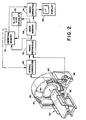
- a tomographic scanner includes a source 40 of penetrating radiation, such as an x-ray tube.
- a radiation detection means 42 receives penetrating radiation which has traversed an image region 44 and a patient or other examined object disposed therein.
- the radiation detection means is a bank of scintillation crystals and photodiodes.
- other electronics which convert received radiation into electrical signals which vary in accordance with the relative intensity thereof may be used.
- a gantry or rotating frame means 46 supports at least the radiation source 40 for rotation about the image region 44 under the control of an electric motor or other rotating means 48.
- a patient support table 50 is mounted to support the phantom, a patient, or other object to be examined within the image region 44.
- a phantom and patient positioning means 52 selectively positions the phantom, patient, or other examined object longitudinally through the image region.
- the detection means 42 is connected with signal correction circuitry or means 60 which performs conventional corrections on the radiation detector data, such as beam hardness corrections, electronic filter compensations, and the like. Moreover, the signal correction means 60 may correct the radiation detector data in accordance with the data stored from previously scanned phantom sections as is explained herein below.
- An image reconstruction means 62 reconstructs a representation of an image of the slice of the phantom, patient, or other object disposed in the image region 44. A convolution and back projection or other known image reconstruction system may be utilized.
- the reconstructed image representation includes a grid of numbers which represent radiation intensity or, conversely, radiation attentuation at a corresponding pixel of the image region.
- the reconstructed image of a patient under examination is stored in an image memory 64 for display on a video monitor 66 or other suitable display means or for storage on tape or other electronic storage mediums. Optimally, only selected information from the image representation may be stored or displayed.
- the phantom described in conjunction with FIGURE 1 Prior to imaging a patient, the phantom described in conjunction with FIGURE 1 is positioned on the patient table and examined in the image region. At least preselected information from reconstructed image representations of the phantom taken at a plurality of cross sections is stored in a correction memory 70.
- the size of the cross section which each image represents may be input into the correction memory directly from the positioning means 52, may be manually entered, or may be calculated by a size calculating means 72.
- the size calculating means determines the diameter, girth, or other dimension of a transverse slice stored in the image memory 64.
- a patient is placed on the patient table and positioned such that the image region is disposed between the L2 and L5 vertebrae.
- a patient image representation is reconstructed from the radiation data to produce an uncorrected patient image in the image memory 64.
- the slice size calculation means 72 determines the diameter or other appropriate measurement of the size of the imaged patient slice.
- the size calculation means addresses the correction memory 70 to retrieve the phantom image representation information which corresponds to the most similarly sized cross section of the phantom.
- An image correction circuit or means 74 adjusts the patient image representation from the image memory 64 in accordance with the addressed phantom image representation information in the correction memory 72 to adjust or calibrate the gray scale or CT numbers with precision.
- the signal correction means 60 may correct the radiation detector data in accordance with the data from the correction memory 70.
- the display means 66 displays the corrected image or may display the CT numbers for one or more selected pixels thereof.
- the phantom is utilized to reload the correction memory 70 at the beginning of each period of operation.
- the phantom may be used to reload the correction memory immediately before or after the examination of each patient. If the correction memory is reloaded immediately before or after each patient scan, then only the phantom portion which corresponds in size to the slice of the patient to be imaged need be examined.
- the data from high and low energy beams may be collected concurrently and processed either serially by the FIGURE 2 circuitry or in parallel by duplicate circuitry.
Landscapes
- Health & Medical Sciences (AREA)
- Life Sciences & Earth Sciences (AREA)
- Engineering & Computer Science (AREA)
- Medical Informatics (AREA)
- General Health & Medical Sciences (AREA)
- Heart & Thoracic Surgery (AREA)
- Surgery (AREA)
- Nuclear Medicine, Radiotherapy & Molecular Imaging (AREA)
- Optics & Photonics (AREA)
- Pathology (AREA)
- Radiology & Medical Imaging (AREA)
- Biomedical Technology (AREA)
- Physics & Mathematics (AREA)
- Molecular Biology (AREA)
- High Energy & Nuclear Physics (AREA)
- Animal Behavior & Ethology (AREA)
- Biophysics (AREA)
- Public Health (AREA)
- Veterinary Medicine (AREA)
- Pulmonology (AREA)
- Theoretical Computer Science (AREA)
- Toxicology (AREA)
- Apparatus For Radiation Diagnosis (AREA)
- Analysing Materials By The Use Of Radiation (AREA)
Claims (19)
Applications Claiming Priority (2)
| Application Number | Priority Date | Filing Date | Title |
|---|---|---|---|
| US06/782,010 US4663772A (en) | 1985-09-30 | 1985-09-30 | Bone mineral analysis phantom |
| US782010 | 1985-09-30 |
Publications (2)
| Publication Number | Publication Date |
|---|---|
| EP0218367A1 EP0218367A1 (fr) | 1987-04-15 |
| EP0218367B1 true EP0218367B1 (fr) | 1990-12-19 |
Family
ID=25124655
Family Applications (1)
| Application Number | Title | Priority Date | Filing Date |
|---|---|---|---|
| EP86306795A Expired EP0218367B1 (fr) | 1985-09-30 | 1986-09-03 | Fantôme pour analyse minérale d'os |
Country Status (4)
| Country | Link |
|---|---|
| US (1) | US4663772A (fr) |
| EP (1) | EP0218367B1 (fr) |
| JP (1) | JPS6282942A (fr) |
| DE (1) | DE3676267D1 (fr) |
Cited By (1)
| Publication number | Priority date | Publication date | Assignee | Title |
|---|---|---|---|---|
| DE102008016106A1 (de) * | 2008-03-28 | 2009-10-15 | Siemens Aktiengesellschaft | Verfahren zur Herstellung eines Röntgenphantoms und Röntgenphantom |
Families Citing this family (45)
| Publication number | Priority date | Publication date | Assignee | Title |
|---|---|---|---|---|
| EP0228785B1 (fr) * | 1985-11-11 | 1993-01-13 | Teijin Limited | Méthode pour l'évaluation d'os |
| US4837686A (en) * | 1985-11-15 | 1989-06-06 | Picker International | Substance quantification in animal bodies |
| US4779621A (en) * | 1987-02-19 | 1988-10-25 | Picker International, Inc. | Xenon calibration phantom |
| US4873707A (en) * | 1987-09-11 | 1989-10-10 | Brigham & Women's Hospital | X-ray tomography phantoms, method and system |
| US4905150A (en) * | 1988-01-18 | 1990-02-27 | Siemens Aktiengesellschaft | X-ray diagnostics installation with mean parenchyma dose calculator |
| US4882494A (en) * | 1988-02-26 | 1989-11-21 | Michael D. Duncan | Apparatus and method for flooding a nuclear imaging device with radiation from an imaging source |
| FR2629214A1 (fr) * | 1988-03-25 | 1989-09-29 | Thomson Cgr | Procede et systeme d'etalonnage d'un scanner a rayons x en utilisant un seul etalon non circulaire |
| FR2632749B1 (fr) * | 1988-06-10 | 1990-08-24 | Gen Electric Cgr | Procede et systeme d'etalonnage d'un scanner a rayons x en utilisant un ou plusieurs etalons circulaires excentres |
| AT394654B (de) * | 1988-08-08 | 1992-05-25 | Inst Med Physik Vet Med Uni Wi | Testphantom zur laufenden kontrolle der bildguete in der roentgendiagnostik |
| FR2636752B1 (fr) * | 1988-09-16 | 1990-10-26 | Gen Electric Cgr | Procede et systeme de correction des defauts d'images d'un scanner dus aux deplacements de ce dernier |
| FR2638535B1 (fr) * | 1988-10-28 | 1990-12-14 | Gen Electric Cgr | Procede et systeme d'etalonnage d'un scanner a rayons x a partir de l'image d'au moins un etalon |
| US5225979A (en) * | 1988-10-28 | 1993-07-06 | General Electric Cgt Sa | Method and system for calibrating an x-ray scanner from the image of at least one calibration standard |
| US5068788A (en) * | 1988-11-29 | 1991-11-26 | Columbia Scientific Inc. | Quantitative computed tomography system |
| US5138553A (en) * | 1989-03-10 | 1992-08-11 | Expert Image Systems, Inc. | Method and apparatus for bone mineral measurement using a measurement region defined at a selected distance from a styloid bone tip |
| US5005196A (en) * | 1989-03-10 | 1991-04-02 | Expert Image Systems, Inc. | Limb positioning and calibration apparatus for radiographic imaging |
| EP0405013B1 (fr) * | 1989-06-27 | 1994-09-14 | Gendex Corporation | Fantôme pour un appareil de radiographie dentaire panoramique |
| FR2649883B1 (fr) * | 1989-07-20 | 1991-10-11 | Gen Electric Cgr | Procede de correction de la mesure de la densite osseuse dans un scanner |
| FR2656697B1 (fr) * | 1989-12-29 | 1994-01-07 | General Electric Cgr Sa | Procede de mesure de la densite osseuse a l'aide d'un scanner. |
| US5233213A (en) * | 1990-07-14 | 1993-08-03 | Robert Bosch Gmbh | Silicon-mass angular acceleration sensor |
| DE9016046U1 (de) * | 1990-11-26 | 1991-02-14 | Kalender, Willi, Dr., 8521 Kleinseebach | Kalibrierphantom für Knochenmineralmessungen an der Lendenwirbelsäule |
| US5473663A (en) * | 1994-09-12 | 1995-12-05 | General Electric Company | Method for evaluating the performance of detectors in a computed tomography system |
| SE504929C2 (sv) * | 1995-01-12 | 1997-05-26 | Anders Ullberg | Metod och anordning för att mäta benmineralhalten i skelettet |
| FR2737005A1 (fr) * | 1995-07-18 | 1997-01-24 | Ge Medical Syst Sa | Procede d'etalonnage geometrique d'un appareil d'imagerie |
| US5908387A (en) * | 1996-06-21 | 1999-06-01 | Quinton Instrument Company | Device and method for improved quantitative coronary artery analysis |
| US5793835A (en) * | 1997-03-19 | 1998-08-11 | Blanck; Cheryl A. | Quality assurance phantom for tomography and method of use |
| AU8103198A (en) * | 1997-07-04 | 1999-01-25 | Torsana Osteoporosis Diagnostics A/S | A method for estimating the bone quality or skeletal status of a vertebrate |
| US6362471B1 (en) * | 1998-05-14 | 2002-03-26 | University Of Cincinnati | Design of a calibration phantom for in vivo measurement of stable lead or radioactivity in bone |
| US6157028A (en) * | 1998-05-28 | 2000-12-05 | Jrh Biosciences, Inc. | Method for dose mapping to ensure proper amounts of gamma irradiation |
| US6983230B2 (en) * | 2001-09-11 | 2006-01-03 | Sterigenics Us, Inc. | Method and apparatus for simulating a radiation dose delivered to an object |
| US6990222B2 (en) * | 2001-11-21 | 2006-01-24 | Arnold Ben A | Calibration of tissue densities in computerized tomography |
| EP1451753A2 (fr) * | 2001-11-24 | 2004-09-01 | Image Analysis, Inc. | Detection et quantification automatiques de calcium coronarien et de calcium aortique |
| US8649843B2 (en) * | 2001-11-24 | 2014-02-11 | Ben A. Arnold | Automated calcium scoring of the aorta |
| JP5090714B2 (ja) * | 2006-11-08 | 2012-12-05 | 株式会社リガク | 検出値較正方法、x線ct装置、較正用ファントムおよび保持具 |
| US8186880B1 (en) * | 2008-11-27 | 2012-05-29 | Arnold Ben A | Extended and fixed INTable simultaneously imaged calibration and correction methods and references for 3-D imaging devices |
| US8649577B1 (en) | 2008-11-30 | 2014-02-11 | Image Analysis, Inc. | Automatic method and system for measurements of bone density and structure of the hip from 3-D X-ray imaging devices |
| JP5624346B2 (ja) * | 2009-04-03 | 2014-11-12 | 株式会社東芝 | 磁気共鳴イメージング装置 |
| US9254101B2 (en) | 2010-12-31 | 2016-02-09 | General Electric Company | Method and system to improve visceral adipose tissue estimate by measuring and correcting for subcutaneous adipose tissue composition |
| US9271690B2 (en) | 2010-12-31 | 2016-03-01 | General Electric Company | Method and system to estimate visceral adipose tissue by restricting subtraction of subcutaneous adipose tissue to coelom projection region |
| US9179884B2 (en) | 2010-12-31 | 2015-11-10 | General Electric Company | Normalized metrics for visceral adipose tissue mass and volume estimation |
| GB201107385D0 (en) * | 2011-05-04 | 2011-06-15 | Materialise Nv | Medical imaging calibration device |
| US8517608B1 (en) | 2011-08-03 | 2013-08-27 | Ben A. Arnold | System and method for calibration of CT scanners and display of images in density units without the use of water phantoms |
| PL229430B1 (pl) | 2014-08-04 | 2018-07-31 | Univ Slaski | Sposób ustalania parametrów fizycznych badanego obiektu zobrazowanego tomografem komputerowym oraz układ do realizacji tego sposobu |
| JP6330567B2 (ja) * | 2014-08-11 | 2018-05-30 | 株式会社島津製作所 | 放射線撮影用ファントム |
| CN109414235B (zh) * | 2016-05-18 | 2022-10-04 | 瓦里安医疗系统公司 | 使用辐射成像的体模设置和源到表面距离验证 |
| CN119700151A (zh) * | 2023-09-22 | 2025-03-28 | 上海西门子医疗器械有限公司 | 确定受检对象特定区域的灰度值的方法、装置、计算机程序 |
Family Cites Families (7)
| Publication number | Priority date | Publication date | Assignee | Title |
|---|---|---|---|---|
| US3010223A (en) * | 1959-09-02 | 1961-11-28 | Alderson Res Lab Inc | Human equivalent dummy |
| SE373279B (sv) * | 1973-05-11 | 1975-02-03 | Atomenergi Ab | Forfarande och anordning for undersokning av en del av en biologisk vevnad |
| US4433380A (en) * | 1975-11-25 | 1984-02-21 | Philips Medical Systems, Inc. | Tomographic scanner |
| US4247790A (en) * | 1976-01-22 | 1981-01-27 | Westinghouse Electric Corp. | Failsafe train vehicle control signal threshold detector apparatus |
| US4055771A (en) * | 1976-10-26 | 1977-10-25 | Alderson Research Laboratories, Inc. | Test body for a scanning tomographic analytical apparatus |
| JPS5594241A (en) * | 1979-01-11 | 1980-07-17 | Hitachi Medical Corp | Xxray transverse layer device |
| US4233507A (en) * | 1979-05-07 | 1980-11-11 | General Electric Company | Computer tomography table containing calibration and correlation samples |
-
1985
- 1985-09-30 US US06/782,010 patent/US4663772A/en not_active Expired - Lifetime
-
1986
- 1986-09-03 EP EP86306795A patent/EP0218367B1/fr not_active Expired
- 1986-09-03 DE DE8686306795T patent/DE3676267D1/de not_active Expired - Lifetime
- 1986-09-29 JP JP61231068A patent/JPS6282942A/ja active Pending
Cited By (1)
| Publication number | Priority date | Publication date | Assignee | Title |
|---|---|---|---|---|
| DE102008016106A1 (de) * | 2008-03-28 | 2009-10-15 | Siemens Aktiengesellschaft | Verfahren zur Herstellung eines Röntgenphantoms und Röntgenphantom |
Also Published As
| Publication number | Publication date |
|---|---|
| DE3676267D1 (de) | 1991-01-31 |
| EP0218367A1 (fr) | 1987-04-15 |
| US4663772A (en) | 1987-05-05 |
| JPS6282942A (ja) | 1987-04-16 |
Similar Documents
| Publication | Publication Date | Title |
|---|---|---|
| EP0218367B1 (fr) | Fantôme pour analyse minérale d'os | |
| Augat et al. | Accuracy of cortical and trabecular bone measurements with peripheral quantitative computed tomography (pQCT) | |
| Mitcheson et al. | Determination of the chemical composition of urinary calculi by computerized tomography | |
| EP1005286B1 (fr) | Procede de reconstitution de l'image d'un objet balaye avec un dispositif d'imagerie laser | |
| KR102252847B1 (ko) | X선 장치, x선 검사 방법, 데이터 처리 장치, 데이터 처리 방법 및 컴퓨터 프로그램 | |
| US5241576A (en) | Segmented detector containing sub-elements for separate measuring of a fan beam | |
| EP0682497B1 (fr) | Systeme tomographique d'exploration des os pourvu d'un bras en c compact | |
| US4788706A (en) | Method of measurement of x-ray energy | |
| US11610347B2 (en) | Tomographic image processing apparatus and method | |
| EP2046203B1 (fr) | Calibrage de gain de détecteur de rayons x dépendant de la fraction de rayonnement diffusé | |
| US7936909B2 (en) | Method and device for detecting chemical anomalies and/or salient features in soft tissue of an object area | |
| US9943281B2 (en) | X-ray CT apparatus | |
| JPH0732768B2 (ja) | スキャナによる骨濃度の測定値の訂正方法 | |
| Cody et al. | A technique for measuring regional bone mineral density in human lumbar vertebral bodies | |
| CN110720940A (zh) | 一种模体及其在ct检测系统中的应用 | |
| US20040017936A1 (en) | Method, system and computer product for calculating mass scores | |
| US5682036A (en) | Method and apparatus for accurately calibrating an attenuation map for emission computed tomography | |
| US20030048873A1 (en) | Method for improving a radiological examination and device therefor | |
| JPS6331647A (ja) | 骨の無機物含有量の測定装置 | |
| US6651018B2 (en) | Method for correcting calibration values in a calibration table of computed tomography apparatus | |
| JP3279513B2 (ja) | 骨密度測定装置、骨密度測定方法及び骨密度測定用ファントム | |
| Kotzi et al. | Prototype of dual energy X-ray tomodensimeter for lumbar spine bone mineral density measurements; choice of the reconstruction algorithm and first experimental results | |
| Platten | Multi-slice helical CT physics and technology | |
| Boyd et al. | Engineering status of computerized-tomographic scanning | |
| Iortile et al. | Measurement of Computed Tomography Dose Quantities at Some Radiological Units of Abuja Hospitals |
Legal Events
| Date | Code | Title | Description |
|---|---|---|---|
| PUAI | Public reference made under article 153(3) epc to a published international application that has entered the european phase |
Free format text: ORIGINAL CODE: 0009012 |
|
| AK | Designated contracting states |
Kind code of ref document: A1 Designated state(s): DE FR GB NL |
|
| 17P | Request for examination filed |
Effective date: 19870622 |
|
| 17Q | First examination report despatched |
Effective date: 19890803 |
|
| GRAA | (expected) grant |
Free format text: ORIGINAL CODE: 0009210 |
|
| AK | Designated contracting states |
Kind code of ref document: B1 Designated state(s): DE FR GB NL |
|
| ET | Fr: translation filed | ||
| REF | Corresponds to: |
Ref document number: 3676267 Country of ref document: DE Date of ref document: 19910131 |
|
| PG25 | Lapsed in a contracting state [announced via postgrant information from national office to epo] |
Ref country code: GB Effective date: 19910903 |
|
| PLBE | No opposition filed within time limit |
Free format text: ORIGINAL CODE: 0009261 |
|
| STAA | Information on the status of an ep patent application or granted ep patent |
Free format text: STATUS: NO OPPOSITION FILED WITHIN TIME LIMIT |
|
| 26N | No opposition filed | ||
| PG25 | Lapsed in a contracting state [announced via postgrant information from national office to epo] |
Ref country code: NL Effective date: 19920401 |
|
| GBPC | Gb: european patent ceased through non-payment of renewal fee | ||
| NLV4 | Nl: lapsed or anulled due to non-payment of the annual fee | ||
| PG25 | Lapsed in a contracting state [announced via postgrant information from national office to epo] |
Ref country code: FR Effective date: 19920529 |
|
| PG25 | Lapsed in a contracting state [announced via postgrant information from national office to epo] |
Ref country code: DE Effective date: 19920602 |
|
| REG | Reference to a national code |
Ref country code: FR Ref legal event code: ST |