EP0218378A2 - Accouplement d'arbres élastique - Google Patents
Accouplement d'arbres élastique Download PDFInfo
- Publication number
- EP0218378A2 EP0218378A2 EP86306976A EP86306976A EP0218378A2 EP 0218378 A2 EP0218378 A2 EP 0218378A2 EP 86306976 A EP86306976 A EP 86306976A EP 86306976 A EP86306976 A EP 86306976A EP 0218378 A2 EP0218378 A2 EP 0218378A2
- Authority
- EP
- European Patent Office
- Prior art keywords
- vanes
- coupling
- pads
- coupling member
- motion
- Prior art date
- Legal status (The legal status is an assumption and is not a legal conclusion. Google has not performed a legal analysis and makes no representation as to the accuracy of the status listed.)
- Granted
Links
Images


Classifications
-
- F—MECHANICAL ENGINEERING; LIGHTING; HEATING; WEAPONS; BLASTING
- F16—ENGINEERING ELEMENTS AND UNITS; GENERAL MEASURES FOR PRODUCING AND MAINTAINING EFFECTIVE FUNCTIONING OF MACHINES OR INSTALLATIONS; THERMAL INSULATION IN GENERAL
- F16D—COUPLINGS FOR TRANSMITTING ROTATION; CLUTCHES; BRAKES
- F16D3/00—Yielding couplings, i.e. with means permitting movement between the connected parts during the drive
- F16D3/50—Yielding couplings, i.e. with means permitting movement between the connected parts during the drive with the coupling parts connected by one or more intermediate members
- F16D3/64—Yielding couplings, i.e. with means permitting movement between the connected parts during the drive with the coupling parts connected by one or more intermediate members comprising elastic elements arranged between substantially-radial walls of both coupling parts
- F16D3/68—Yielding couplings, i.e. with means permitting movement between the connected parts during the drive with the coupling parts connected by one or more intermediate members comprising elastic elements arranged between substantially-radial walls of both coupling parts the elements being made of rubber or similar material
Definitions
- This invention relates to a rotatable flexible shaft- coupling device which comprises first and second coupling members each connectible drivingly to a respective shaft and flexibly coupled together for the transmission of torque between the coupling members.
- Flexible couplings are often used when either or both of the driving or driven members of a power train are flexibly mounted, because they are able to accommodate radial, axial and lateral misalignment.
- Some flexible couplings can also tolerate variation in the torque being transmitted, e.g. from the power stroke of a slow speed diesel engine, and thus act to smooth the torque irregularities; this property will give a more uniform output torque and may also reduce noise transmission along the power train.
- the present invention has been developed with a view to providing a flexible coupling which can meet all of the above requirements.
- FIGS. 1 and 2 of the accompanying drawings show schematically a pair of conventional flexible couplings comprising coupling disc havles 101, 102 and coupling disc halves 101', 102' linking two shafts together by means of a cardan shaft 103. In Figure 1 there is no misalignment.
- FIG. 3 and 4 of the accompanying drawings The general principle of a flexible shaft-coupling device according to the invention is shown schematically in Figures 3 and 4 of the accompanying drawings, wherein the coupling devices of the invention are denoted by reference numerals 111 and 112 and an annular cardan shaft linking the devices is denoted by reference numeral 113.
- the coupling devices 111 and 112 can accommodate a similar degree of misalignment as Figures 2, and more, without difficulty.
- the coupling device of the invention can also accept a large degree of axial misalignment, this being limited only by the shear limits of the resilient components thereof, and not by the contact of the coupling disc halves as in the conventional coupling.
- each paid is firmly located in axial, radial and circumferential directions with one of the coupling members, whereas the other end of the pad is at least partly unrestrained e.g. completely unrestrained or partially or wholly restrained only in the radial and/or axial direction, relative to the other of the coupling members, whereby the shaft-coupling device of the invention can readily compensate for any misalignments which occur between a pair of shafts which are to be coupled together by the coupling device of the invention, while still providing satisfactory transmission of torque between the shafts via the coupling device.
- the second coupling member comprises an annular member which may be coupled with its respective shaft by any suitable mechanical means, such as by bolts to a shaft flange.
- the first coupling member which is an annular member which surrounds the first and'second sets of vanes and also the distortable pads, may be secured to its respective shaft by any suitable mechanical means.
- the entire device is housed within one end of a hollow shaft, and particularly a hollow cardan shaft of the type suitable for use in a marine transmission system, and a rigid drive connection is established between the first coupling member and the inner periphery of the hollow shaft at the end thereof.
- a pair of shaft-coupling devices of the invention is provided, one being arranged at and within each end of the hollow cardan shaft.
- the hollow cardan shaft may then have an internal diameter which corresponds generally with the overall external diameter of the coupling device, and may therefore be made of relatively lightweight construction.
- the resiliently distortable pads may be arranged so that those which are used to transmit torque between the vanes of the first and second set for said one predominant direction of rotational motion may be made to be thicker than the pads which are used to transmit torque for the other direction of rotation.
- alternate pads may be of different thickness.
- one end is fast with one of the vanes whereas its opposite end may be completely unrestrained.
- a lubricant may therefore be provided to promote slippage of the unrestrained end, such as a low friction coating.
- a flexible shaft-coupling device which comprises a first coupling member 7 which is connectible drivingly to a respective shaft 10 and a second coupling member 3 which is connectible drivingly to a respective shaft 1.
- the first and second coupling members are flexibly coupled together for the transmission of torque between the coupling members.
- the first coupling member 7 is an annular member having a first set of circumferentially spaced vanes 6 which are provided on the inner periphery of the annular member and which extend radially inwardly therefrom.
- the second coupling member 3 is arranged approximately co-axially and radially inwardly of the inner periphery of the first coupling member 7, and has a second set of circumferentially spaced vanes 5 which extend radially outwardly of the second coupling member 3 so as to be located each in a respective one of the circumferential spaces, designated generally by reference 6A, which are defined between the adjacent vanes 6 of the first set.
- Each vane 5 of the second set sub-divides its respective space 6A in which it is received into a pair of gaps 6B with the adjacent vanes 6 of the first set.
- a plurality of circumferentially spaced and resiliently distortable pads 8 is arranged one in each of the gaps 6B to provide for resilient and flexible torque transmission between the vanes 6, 5 of the first and second sets of vanes.
- each pad is composed of laminations of a first resilient material and a second material that is less resilient than the first material, and each pad is secured at one (radially extending) end to a vane at one end of the respective gap 6B and is arranged to have at least partial freedom of motion at its opposite (radially extending) end relative to the vane at the other end of the gap.
- each pad is firmly located in axial, radial and circumferential directions with one of the coupling members (3, 7), whereas the other end of the pad is at least partly unrestrained e.g. completely unrestrained or partially or wholly restrained only in the radial and/or axial direction, relative to the other of the coupling members, whereby the shaft coupling device of the invention can readily compensate for any misalignments which occur between a pair of shafts (1, 10) which are to be coupled-together by the coupling device, while still providing satisfactory transmission of torque between the shafts via the coupling device.
- the second coupling member 3 which takes the form of an annular web, is coupled drivingly with shaft 1 via a ring of bolts 4, whereas the first coupling member 7 is coupled drivingly with shaft 10 via bolts 9.
- the radial vanes 5 are secured fast with the annular web 3, and extend radially outwards therefrom.
- the vanes 5 engage with an equal number of the vanes 6, which extend radially inwards from an annular portion of the first coupling member 7.
- the numbers of vanes (5, 6) in the first and second set are equal, so that the vanes can engage in an essentially co-axial manner.
- the flexible pads 8 are disposed between each adjacent pair of vanes 5 and 6, in both the forward and reverse senses of rotation, so that there are twice the number of flexible pads 8 as there are vanes in each set.
- each flexible pad 8 is fast with a radial vane at one end of gap 6B, but has some, or complete, freedom of motion at its opposite end relative to the radial vane at the other end of gap 6B.
- each load-bearing flexible pad 8 will be fast with one of the vanes of the-same set.
- all flexible pads 8 are fast at one end with one of the radial vanes 5 (45, Fig. ⁇ 7).
- all pads 8 could be fast with one of the radial vanes 6 (46).
- shaft 1 When shaft 1 is the input shaft, the drive would then pass from circumferential coupling member 7, via bolts 9, to shaft 10 which is an annular cardan shaft. It is normal practice to use two flexible couplings at either end of a cardan shaft, as shown in Figures 1 and 2. Thus for the second flexible coupling (not shown) at the other end of shaft 10, annular cardan shaft 10 would become the input member and the drive would thus pass via bolts 9, through circumferential member 7 (now acting as an input member), via radial vanes 6, flexible pads 8, radial vanes 5 and thence to shaft 1, now acting as the output member.
- vanes 5 and 6 are integral with web 3 and member 7 respectively. These two components, 5, 3 and 6, 7, may be manufactured by any of several methods, including fabrication, casting and forging. Of these, forging has the advantage of providing better mechanical strength if care is taken to control the metallurgical properties.
- the coupling described herein is designed to take advantage of this, and in particular, to provide a grain direction giving best strength in the region of great stress, at the vane roots. Working to higher permitted stress levels has the advantage of enabling coupling size and weight to be reduced.
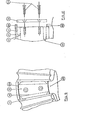
- FIG 7 shows in more detail the construction and arrangement of the pads between the vanes.
- Parts 43, 45, 46 and 48 of Figure 7 correspond to parts 3, 5, 6 and 8 respectively of Figures 5 and 6.
- Figure 7 shows an enlarged view of one flexible pad 48, between one of the set of radial vanes 45 and one of the set of radial vanes 46.
- the method of assembly of the coupling will now be described. The assembly would be done in a jig for alignment purposes.
- Annular web 43 carrying radial vanes 45 would be suitably mounted, e.g. on the end of a mandrel similar to flange 2 ( Figure 5) and the circumferential coupling member carrying vanes 46 would be mounted co-axially around it.
- the advantage of this method of mounting is that unrestricted access is available to one face of the coupling.
- the pads may now be slid into place between adjacent radial vanes 45 and 46.
- dovetail-shaped cut-outs 40 have been machined.
- the end faces of flexible pads 48 are formed by two end plates 41 and 42; one of these plates 41 is machined with a male dovetail to match dovetail cut-out 40.
- pad 48 may be slid axially into place.
- a clearance 44 is provided at the other end of pad 48 where end plate 42 would bear on second radial vane 46 when under operational load; clearance 44 is essential to permit assembly of the coupling.
- end piece 41 When end piece 41 is fully home in dovetail slot 40, it may be secured in position by means of a keeper 53 ( Figure 8).
- the keeper is shown in more detail in Figures 9 and 10.
- the surface of the upper portion of each vane 45 is machined away to leave projections 45A and 45B.
- the keeper 53 is secured in position with screws 53A.
- the keeper 53 overlaps the end of the dovetails of end plates 41 and secures them against movement in the axial direction.
- Dovetail cut-outs 40 are merely quoted as one of many means by which end pieces 41 (51 in Figure 8) may be secured to first radial vanes 45 (55 in Figure 8) and other suitable means will be obvious to the skilled person. Furthermore, for ease of manufacture, dovetail cut-outs may be machined right across the faces of radial vanes 45 and keeper plates 53 used at both ends of the cut-outs 40 to positively retain end pieces 41 in both axial directions.
- Figure 7 shows that end plate 42 will bear directly onto the flat face of second radial vane 46 under operational load.
- the first end of pad 48 i.e. dovetail end plate 41
- dovetail cut-out 40 i.e. it is fast with vane 45 in the radial, axial and circumferential directions (as defined by the axis through the coupling ( Figure 5)).
- the second end of pad 48 i.e. end plate 42
- the nature and method of construction of the flexible pads (8, 48) will now be described by reference to Figures 7 and 8.
- parts denoted by reference numerals 50, 51, 52, 54, 55, 56, 57, 58 and 59 correspond to parts 40, 41, 42, 44, 45, 46, 47, 48 and 49 respectively of Figure 7.
- the flexible pads 48, 58 consist of alternating thick layers of a suitable resilient substance 49, 59 separated by thin layers of a suitable less resilient substance 47, 57.
- members of the same or another less resilient substance are used to facilitate fixing of the pad, i.e. dovetail end plate 41, 51, and load bearing end plate 42, 52.
- rubber may be used as the resilient substance with the particular formulation of the polymer being varied according to the bearing pressure on the pad, i.e. a combination of the torque being transmitted, the pad area and the number of pads carrying load.
- steel may be used for the less resilient substance.
- end plates 41, (51) and 42, (52) will be placed in a mould and a plurality of thin steel plates 47, (57) added and held in a jig at the required angle and spacing.
- the mould is then filled with raw rubber which is then suitably polymerised or cured.
- This process results in a resilient substance, strongly bonded to the metallic plates and able to accept high compressive loading, being formed between end plates 41 and 42.
- Such a composite construction makes the pads very flexible under shear loading.
- rubber and steel have been quoted as examples of the resilient and less resilient substances respectively, a wide range of other substances and combinations of substances may be used depending on the duty required.
- all the metal plates 41, 42 and 47 ( Figure 7) extend to cover at least the full area of the rubber pads; this is necessary to protect the edges of the rubber sections where any failure would be likely to be initiated.
- the flexible coupling thus described uses flexible rubber pads 8, 48, 58 to transmit the driving torque by direct compression of the pads. Misalignment is accommodated by shear of the rubber elements 49, 59 of the pads.
- rubber can withstand high compressive stress, moderate shear stress, but only very low tensile stresses.
- the presence of the metal plates 47, 57 improves resistance to compressive stress, so that a relatively thick rubber/metal multi-layered pad can accommodate a much higher loading pressure than could a pad of the same thickness made only of rubber.
- a (circumferentially) thick pad is required to accommodate gross misalignment without the shear stress in the rubber reaching unacceptable levels.
- the design of flexible coupling disclosed herein is capable of transmitting high torques while accommodating high levels of axial, lateral and angular misalignment.
- Figure 2 shows a conventional type of coupling at the limits of its misalignment (angular and lateral) capability, as the two halves of each coupling are in contact.
- the coupling of the invention shown in Figure ' 4 has not reached the limit of its misalignment capability.
- end plates 42 are not recessed into radial vanes 46, considerably greater misalignment than shown may be tolerated.
- a further advantage of the present flexible coupling is that rubber pads 8, 48 and 58 transmit the load between vanes 5 and 6, i.e. there is no metal-to- metal contact between input and output members.
- rubber pads 8, 48 and 58 transmit the load between vanes 5 and 6, i.e. there is no metal-to- metal contact between input and output members.
- This attenuation will be greater if two couplings are used as there will be two sets of rubber pads to act in series.
- a further advantage of rubber pads is that they are resilient and compressible under load.
- the inertia of the cardan shaft assembly, together with the resilience of the rubber will act to reduce the torsional fluctuations, and minimise the possibility of torsional vibration.
- Such torsional damping would be particularly useful if the coupling was used to transmit drive from a petrol or diesel internal combustion engine, such engines by their nature exhibiting a cyclic torque variation, which cannot be fully eliminated by use of a flywheel.
- Figures 5, 6, 7 and 8 show a flexible coupling in which the pads to take the drive under forward and reverse directions of motion are of equal thickness i.e. alternate pads are of equal thickness.
- alternate pads are of equal thickness.
- the reverse torque is lower than that when rotating in the principle direction.
- the thickness of the reverse pads may be reduced so that alternate pads are of unequal thickness. The advantage of this would be to permit an overall reduction in coupling diameter for a given power.
- end plates 42 there must be no recess present. This will allow end plates 42 to slip over the surface of radial vanes 46 so that, in the reverse direction of rotation, misalignment can be accommodated by a combination of shear in the rubber and slippage of end plate 42 over the surface of radial vane 46. Slipping of the end plate 42 may be promoted by the use of low friction coatings.
- vanes 5 and 6 (45 and 46) have been shown as 'radial'. This has meant that the flexible pads 8, (48) are wedge-shaped.
- parallel-sided pads may be preferable. To use parallel-sided pads, the angle included between the two faces of first vanes 5(45) would be increased and that included between the two faces of second vanes 6(46) would be reduced.
- wedge-shaped end pieces 41, 42 could be used instead. In other cases, e.g. for ease of manufacture, it may be desirable to have both first and second vanes 5, 6 (45, 46) parallel-sided. In this case, the wedge angle of the pads 8, (48) may be appropriately increased. Alternatively wedge-shaped end pieces 41, 42 could be used. A combination of wedge-shaped pads 48 and wedge-shaped end pieces 41, 42 is also possible.
- Figures 1 and 2 show two couplings connected together by a cardan shaft, it is equally possible for a single coupling to be used.
- the annular output member would be connected, via a disc-like member, to the output shaft.
Landscapes
- Engineering & Computer Science (AREA)
- General Engineering & Computer Science (AREA)
- Mechanical Engineering (AREA)
- Mechanical Operated Clutches (AREA)
Applications Claiming Priority (4)
| Application Number | Priority Date | Filing Date | Title |
|---|---|---|---|
| GB858524497A GB8524497D0 (en) | 1985-10-04 | 1985-10-04 | Flexible shaft-coupling device |
| GB8524497 | 1985-10-04 | ||
| GB8619751A GB2186053B (en) | 1985-10-04 | 1986-08-13 | A flexible shaft-coupling device |
| GB8619751 | 1986-08-13 |
Publications (3)
| Publication Number | Publication Date |
|---|---|
| EP0218378A2 true EP0218378A2 (fr) | 1987-04-15 |
| EP0218378A3 EP0218378A3 (en) | 1987-11-11 |
| EP0218378B1 EP0218378B1 (fr) | 1991-07-31 |
Family
ID=26289844
Family Applications (1)
| Application Number | Title | Priority Date | Filing Date |
|---|---|---|---|
| EP86306976A Expired - Lifetime EP0218378B1 (fr) | 1985-10-04 | 1986-09-10 | Accouplement d'arbres élastique |
Country Status (3)
| Country | Link |
|---|---|
| US (1) | US4816007A (fr) |
| EP (1) | EP0218378B1 (fr) |
| DE (1) | DE3680628D1 (fr) |
Cited By (2)
| Publication number | Priority date | Publication date | Assignee | Title |
|---|---|---|---|---|
| US6358154B1 (en) | 1998-02-20 | 2002-03-19 | Marconi Marine (Vsel) Limited | Flexible coupling |
| WO2011003515A1 (fr) * | 2009-07-09 | 2011-01-13 | Voith Patent Gmbh | Accouplement élastique |
Families Citing this family (4)
| Publication number | Priority date | Publication date | Assignee | Title |
|---|---|---|---|---|
| US5810668A (en) * | 1996-04-12 | 1998-09-22 | Simpson International (Uk) Ltd. | Torsional shock isolated fuel pump drive gear assembly |
| PT2753346T (pt) * | 2011-09-07 | 2020-05-22 | Sinai School Medicine | Ceramidase e diferenciação celular |
| US10060088B2 (en) * | 2015-03-20 | 2018-08-28 | Gaston Contant Inc. | Driving arrangement and cooling system for a snow blower device |
| DE102018010053A1 (de) | 2018-12-19 | 2020-06-25 | Siemens Mobility GmbH | Kupplungsvorrichtung |
Family Cites Families (11)
| Publication number | Priority date | Publication date | Assignee | Title |
|---|---|---|---|---|
| US1561476A (en) * | 1923-04-02 | 1925-11-17 | Int Motor Co | Torque-cushioning device |
| US2157996A (en) * | 1938-08-09 | 1939-05-09 | Brownstein Benjamin | Universal flexible and safety coupling |
| US3094853A (en) * | 1961-12-15 | 1963-06-25 | Gomma Antivibranti Applic | Flexible transmission coupling |
| US3102402A (en) * | 1962-10-31 | 1963-09-03 | Koppers Co Inc | Misalignment device for flexible couplings |
| DE1525388A1 (de) * | 1965-02-09 | 1969-07-10 | Turboflex Ltd | Flexible Kupplung |
| GB1211689A (en) * | 1966-12-14 | 1970-11-11 | Metalastik Ltd | Improvements in or relating to flexible transmission couplings |
| GB1185737A (en) * | 1967-07-17 | 1970-03-25 | Vickers Ltd | Improvements in or relating to Flexible Couplings |
| US3485062A (en) * | 1968-02-26 | 1969-12-23 | Michael P Blake | Flexible coupling |
| DE2027349B2 (de) * | 1970-06-04 | 1971-12-23 | Braunschweigische Maschinenbau anstalt, 3300 Braunschweig | Kardangelenkartig wirkende doppelzahnkupplung |
| US4627885A (en) * | 1983-11-17 | 1986-12-09 | Ltv Energy Products Company | Method of producing a compression loaded torsional coupling device |
| DE3403910A1 (de) * | 1984-02-04 | 1985-08-08 | Thyssen Industrie Ag, 4300 Essen | Kardanische doppelkupplung |
-
1986
- 1986-09-10 EP EP86306976A patent/EP0218378B1/fr not_active Expired - Lifetime
- 1986-09-10 DE DE8686306976T patent/DE3680628D1/de not_active Expired - Fee Related
- 1986-09-24 US US06/910,919 patent/US4816007A/en not_active Expired - Fee Related
Cited By (2)
| Publication number | Priority date | Publication date | Assignee | Title |
|---|---|---|---|---|
| US6358154B1 (en) | 1998-02-20 | 2002-03-19 | Marconi Marine (Vsel) Limited | Flexible coupling |
| WO2011003515A1 (fr) * | 2009-07-09 | 2011-01-13 | Voith Patent Gmbh | Accouplement élastique |
Also Published As
| Publication number | Publication date |
|---|---|
| DE3680628D1 (de) | 1991-09-05 |
| EP0218378A3 (en) | 1987-11-11 |
| EP0218378B1 (fr) | 1991-07-31 |
| US4816007A (en) | 1989-03-28 |
Similar Documents
| Publication | Publication Date | Title |
|---|---|---|
| EP0456384B1 (fr) | Biellette de liaison et palier pour accouplement rotatif | |
| US3759063A (en) | Laminated diaphragm couplings | |
| US5117704A (en) | Elastomeric torsional isolator | |
| US4690661A (en) | Torsional stress distribution flexible coupling | |
| GB2041494A (en) | Flexible couplings | |
| US4050266A (en) | Drive coupling | |
| US2883839A (en) | Flexible drive shaft | |
| US20250180076A1 (en) | Coupling | |
| US4816007A (en) | Radially interengaged vane coupling with circumferentially arranged resilient pads | |
| US4207758A (en) | High speed shaft flexible coupling with maximum shaft misalignment accommodation capability | |
| EP1390633A1 (fr) | Dispositif d'isolation contre les fluctuations de couple | |
| US5186292A (en) | Torque converter and clutch with compliance interface | |
| US4196597A (en) | Flexible shaft couplings with axially spaced diaphragms | |
| US6358154B1 (en) | Flexible coupling | |
| EP0218377A2 (fr) | Accouplements élastiques | |
| US4671780A (en) | Flexible coupling with deformable beam elements | |
| US3940947A (en) | Resilient driving connections | |
| US3791169A (en) | Torsionally resilient shaft coupling | |
| GB2186053A (en) | A flexible shaft-coupling device | |
| CA1207158A (fr) | Accouplement antivibrations | |
| JPS60125418A (ja) | 回転弾性カツプリング | |
| RU2153607C2 (ru) | Гибкая муфта для трансмиссионных систем | |
| US5722522A (en) | Overrunning multiple-row sprag clutch | |
| RU2017022C1 (ru) | Упругая муфта | |
| US6231449B1 (en) | Torsional vibration coupling |
Legal Events
| Date | Code | Title | Description |
|---|---|---|---|
| PUAI | Public reference made under article 153(3) epc to a published international application that has entered the european phase |
Free format text: ORIGINAL CODE: 0009012 |
|
| AK | Designated contracting states |
Kind code of ref document: A2 Designated state(s): DE FR IT NL |
|
| PUAL | Search report despatched |
Free format text: ORIGINAL CODE: 0009013 |
|
| AK | Designated contracting states |
Kind code of ref document: A3 Designated state(s): DE FR IT NL |
|
| 17P | Request for examination filed |
Effective date: 19880427 |
|
| 17Q | First examination report despatched |
Effective date: 19880908 |
|
| GRAA | (expected) grant |
Free format text: ORIGINAL CODE: 0009210 |
|
| AK | Designated contracting states |
Kind code of ref document: B1 Designated state(s): DE FR IT NL |
|
| PG25 | Lapsed in a contracting state [announced via postgrant information from national office to epo] |
Ref country code: NL Effective date: 19910731 Ref country code: IT Free format text: LAPSE BECAUSE OF FAILURE TO SUBMIT A TRANSLATION OF THE DESCRIPTION OR TO PAY THE FEE WITHIN THE PRE;WARNING: LAPSES OF ITALIAN PATENTS WITH EFFECTIVE DATE BEFORE 2007 MAY HAVE OCCURRED AT ANY TIME BEFORE 2007. THE CORRECT EFFECTIVE DATE MAY BE DIFFERENT FROM THE ONE RECORDED.SCRIBED TIME-LIMIT Effective date: 19910731 |
|
| REF | Corresponds to: |
Ref document number: 3680628 Country of ref document: DE Date of ref document: 19910905 |
|
| ET | Fr: translation filed | ||
| NLV1 | Nl: lapsed or annulled due to failure to fulfill the requirements of art. 29p and 29m of the patents act | ||
| PGFP | Annual fee paid to national office [announced via postgrant information from national office to epo] |
Ref country code: DE Payment date: 19920203 Year of fee payment: 6 |
|
| PLBE | No opposition filed within time limit |
Free format text: ORIGINAL CODE: 0009261 |
|
| STAA | Information on the status of an ep patent application or granted ep patent |
Free format text: STATUS: NO OPPOSITION FILED WITHIN TIME LIMIT |
|
| 26N | No opposition filed | ||
| PG25 | Lapsed in a contracting state [announced via postgrant information from national office to epo] |
Ref country code: DE Effective date: 19930602 |
|
| PGFP | Annual fee paid to national office [announced via postgrant information from national office to epo] |
Ref country code: FR Payment date: 19930929 Year of fee payment: 8 |
|
| PG25 | Lapsed in a contracting state [announced via postgrant information from national office to epo] |
Ref country code: FR Effective date: 19950531 |
|
| REG | Reference to a national code |
Ref country code: FR Ref legal event code: ST |