EP0218509A1 - Federungsaggregat für Fahrzeuge mit Dämpfungsmittel - Google Patents
Federungsaggregat für Fahrzeuge mit Dämpfungsmittel Download PDFInfo
- Publication number
- EP0218509A1 EP0218509A1 EP86402034A EP86402034A EP0218509A1 EP 0218509 A1 EP0218509 A1 EP 0218509A1 EP 86402034 A EP86402034 A EP 86402034A EP 86402034 A EP86402034 A EP 86402034A EP 0218509 A1 EP0218509 A1 EP 0218509A1
- Authority
- EP
- European Patent Office
- Prior art keywords
- arm
- support
- axis
- relative
- rotation
- Prior art date
- Legal status (The legal status is an assumption and is not a legal conclusion. Google has not performed a legal analysis and makes no representation as to the accuracy of the status listed.)
- Withdrawn
Links
- 238000013016 damping Methods 0.000 title claims abstract description 79
- 239000000725 suspension Substances 0.000 title claims abstract description 60
- 230000000295 complement effect Effects 0.000 claims abstract description 19
- 239000012530 fluid Substances 0.000 claims description 71
- 238000005096 rolling process Methods 0.000 claims description 32
- 238000005086 pumping Methods 0.000 claims description 18
- 238000001914 filtration Methods 0.000 claims description 5
- 230000000670 limiting effect Effects 0.000 claims description 5
- 230000005693 optoelectronics Effects 0.000 claims description 2
- 238000007599 discharging Methods 0.000 claims 2
- 238000010438 heat treatment Methods 0.000 abstract description 5
- 230000003068 static effect Effects 0.000 description 19
- 238000006073 displacement reaction Methods 0.000 description 13
- 210000000056 organ Anatomy 0.000 description 13
- 230000000694 effects Effects 0.000 description 10
- 238000005192 partition Methods 0.000 description 7
- 238000010586 diagram Methods 0.000 description 4
- 239000004020 conductor Substances 0.000 description 3
- 238000005520 cutting process Methods 0.000 description 3
- 230000007423 decrease Effects 0.000 description 3
- 238000011161 development Methods 0.000 description 3
- 230000036961 partial effect Effects 0.000 description 3
- 238000007789 sealing Methods 0.000 description 3
- IJGRMHOSHXDMSA-UHFFFAOYSA-N Atomic nitrogen Chemical compound N#N IJGRMHOSHXDMSA-UHFFFAOYSA-N 0.000 description 2
- 238000004891 communication Methods 0.000 description 2
- 230000006835 compression Effects 0.000 description 2
- 238000007906 compression Methods 0.000 description 2
- 238000001816 cooling Methods 0.000 description 2
- 230000006378 damage Effects 0.000 description 2
- 239000007789 gas Substances 0.000 description 2
- 238000005304 joining Methods 0.000 description 2
- 239000000463 material Substances 0.000 description 2
- 230000003287 optical effect Effects 0.000 description 2
- 230000002441 reversible effect Effects 0.000 description 2
- 239000007787 solid Substances 0.000 description 2
- 101100536354 Drosophila melanogaster tant gene Proteins 0.000 description 1
- 241000287107 Passer Species 0.000 description 1
- -1 advantageously Chemical compound 0.000 description 1
- 238000013459 approach Methods 0.000 description 1
- 238000006243 chemical reaction Methods 0.000 description 1
- 230000021615 conjugation Effects 0.000 description 1
- 238000012937 correction Methods 0.000 description 1
- 230000001419 dependent effect Effects 0.000 description 1
- 230000006866 deterioration Effects 0.000 description 1
- 230000009365 direct transmission Effects 0.000 description 1
- 238000009826 distribution Methods 0.000 description 1
- 229940082150 encore Drugs 0.000 description 1
- 238000004519 manufacturing process Methods 0.000 description 1
- 238000000034 method Methods 0.000 description 1
- 229910052757 nitrogen Inorganic materials 0.000 description 1
- 238000013021 overheating Methods 0.000 description 1
- 230000002093 peripheral effect Effects 0.000 description 1
- 230000007425 progressive decline Effects 0.000 description 1
- 230000002829 reductive effect Effects 0.000 description 1
- 230000000284 resting effect Effects 0.000 description 1
- 230000035945 sensitivity Effects 0.000 description 1
- 230000001052 transient effect Effects 0.000 description 1
- 238000013519 translation Methods 0.000 description 1
Images


Classifications
-
- B—PERFORMING OPERATIONS; TRANSPORTING
- B62—LAND VEHICLES FOR TRAVELLING OTHERWISE THAN ON RAILS
- B62D—MOTOR VEHICLES; TRAILERS
- B62D55/00—Endless track vehicles
- B62D55/08—Endless track units; Parts thereof
- B62D55/104—Suspension devices for wheels, rollers, bogies or frames
- B62D55/112—Suspension devices for wheels, rollers, bogies or frames with fluid springs, e.g. hydraulic pneumatic
- B62D55/1125—Hydro-pneumatic or pneumatic, e.g. air-cushioned
Definitions
- the present invention relates to a suspension member for a vehicle, provided with damping means.
- the damping means are of the hydraulic type and employ two chambers of hydraulic fluid which are placed inside the arm and whose volumes vary concomitantly, conversely one of the other, when the arm pivots about the second axis relative to the support; the two chambers are connected by means defining a constriction, which allow a passage of fluid from one chamber to the other, slowly enough to dampen the rotation of the arm.
- connection conduits are particularly vulnerable and represent a disadvantage which is all the more significant as the suspensions of the type indicated in the preamble generally equip civil or military vehicles intended to operate on particularly difficult terrain, on which the risks of damage to such conduits are significant.
- the means of damping by hydraulic fluid provided to date in suspensions with swinging arms only meet this criterion up to a second threshold of speed of vertical movement of the rolling member relative to the vehicle; as soon as this second threshold is exceeded, the force or moment of damping begins to increase again with the speed of vertical displacement of the rolling member relative to the vehicle, and can go as far as reaching values suitable for causing the deterioration, or even destruction, of the hydraulic circuit and of the hydraulic fluid constituting the damping means.
- the hydraulic fluid then no longer plays a role in the actual damping, the heating phenomena linked to the damping then appearing at the level of the complementary friction braking members that are less vulnerable and easier to cool, and the value of the effort or the moment of amortization then remains limited, but on the one hand the evolution of this effort or of this moment and on the other hand the structure of the means of amortization, inextricably linked, recommended in the two documents above can not be considered fully satisfactory since, in particular, one can not influence the damping during the rotation of the arm in the second direction.
- hydraulic fluid can optionally be used as a means of controlling the pressure for bringing into mutual contact of the complementary friction braking members at the speed of rotation of the arm relative to the support, this hydraulic fluid plays no role. in the actual damping, which makes it possible to avoid the problems in particular of overheating linked to the usual use of hydraulic fluid as a damping means.
- means acting in particular by filtration of said first or second signal are provided to limit said contacting pressure as well as to make it insensitive to slow pivoting, or of low amplitude, or of high frequency, of the arm relative to the support.
- the capture means can be of electro-mechanical or electromagnetic type, or opto-electronic, in which case said signal is electrical and the control means of electronic or electro-hydraulic or electro-mechanical type; however, it is also possible to use capture means and control means of the mechanical-hydraulic type, said signal then being of the hydraulic type.
- the means for controlling the pressure for bringing into mutual contact of the complementary braking members comprise a cam secured to one of the mutually movable elements which respectively constitute the support and the arm, and pumping pistons immobilized relative to the other of these elements, against a rotation about the axis of rotation of the arm relative to the support, which pistons are moved by the cam during rotation of the arm relative to the support and thus deliver, as a function of the speed, and possibly of the angle of rotation of the arm relative to the support, a flow of hydraulic fluid used to ensure mutual contact, under pressure, additional braking devices; for this purpose, provision is made, bypassing on the connection circuit between the pumping pistons and the means for bringing the braking devices into mutual contact, a throttle leading to a reservoir of hydraulic fluid, this throttle authorizing a leakage rate calibrated, engen drant a pressure drop itself determining the pressure in said connecting circuit; under a compact and easy to make structure, it is thus possible to control precisely the pressure of mutual application
- the heating source consists almost exclusively of the complementary friction braking members, in mutual contact, which can advantageously be reduced dir by establishing in their surroundings a circulation of a hydraulic fluid which is stirred during the rotational movements of the arm relative to the support and which, advantageously, constitutes a reserve from which the pumping pistons draw during said movements.
- the suspension member according to the invention 1 is illustrated in positions of equilibrium which it is capable of occupying while it is mounted on a vehicle of which a frame has been shown schematically at 2, and that this vehicle rests on a horizontal plane by means of a rolling member shown diagrammatically at 3, such as a wheel or a track roller, depending on the type of vehicle considered.
- the suspension member 1 which has been illustrated comprises a support 4 in the form of a vertical plate 6 which can be secured, for example by bolting 5, with the frame of the vehicle and which itself carries in an integral manner, for example in one piece with it, a shaft 7 having an average direction 8 horizontal, perpendicular to the plate 4; when the support 4 is secured to the frame 2 of the vehicle, the shaft 7 protrudes outside of it.
- the shaft 7 itself carries in solidarity, in particular against a rotation about an axis defined by its mean direction 8, a crank 9 which cooperates for this purpose with the shaft 7 by complementarity of shapes ; for example, the crank 9 has a bore 10 by which it fits on the shaft 7 and, transversely with respect to the axis 8, the bore 10 and the shaft 7 have respective polygonal, complementary sections, as shown in Figure 2; any other form of mutual securing of the crank 9 and of the shaft 7 in particular against a relative rotation around the axis 8 could be used without departing from the scope of the present invention; for example, one could use for this purpose a traditional keying, or a cooperation of the bore 10 and the shaft 7 by complementary grooves.
- the crank 9 forms on the one hand, above the shaft 7, a yoke 11 integrally carrying a pin 12 with an axis 13 located parallel to the axis 8, above the latter and in a same vertical plane 14 as this; this axis 13 is like the axis 8 fixed relative to the support 4; on the other hand, respectively on either side of the yoke 11 in a direction parallel to the axis 8, the crank 9 integrally defines two sleeves 20 and 21 located respectively between the yoke 11 and the plate 6, and opposite the plate 6 relative to the yoke 11; each of the sleeves 20 and 21 integrally carries the inner cage of a respective thrust bearing 16, 17 furthermore having an outer cage secured respectively to a housing 18 or a housing flange 19, one and the other annular and mutually integral, for guiding the housing 18 and the housing flange 19 in rotation about the axis 8 relative to the crank 9 and the shaft 7 without possibility of relative translation parallel to axis 8; for this purpose, in addition, the inner cages of the bearings 16 and 17 are
- the housing 18 is sealed and envelops the crank 9 on the side of the plate 6 of the support 4 and in the direction of a radial distance with respect to the axis 8; around the bearing 16 and the sleeve 20, the casing housing 18 projects towards the plate 6 an annular ring 23 of revolution around the axis 8, which ring 23 is engaged, with the possibility of relative rotation about the axis 8, in a complementary groove 24 arranged in the plate 6 of the seals 25, 26 whose choice and position are easily determinable by a person skilled in the art provide a seal between the plate 6, which is itself sealed, and the crown 23 which is also sealed.
- the flange 19, also leaktight, is secured in a leaktight manner with the case 18 and covers the crank 9 opposite the case 18; it has an orifice of revolution around the axis 8, closed in leaktight manner by an attached cover 27, in the general shape of a disc perpendicular to the axis 8; similarly, an orifice in the housing 18 is sealed off by an attached cover 28, so that the support 4, the housing housing 18, the housing flange 19, the cover 27, the cover 28 together define a sealed housing 22 enclosing in particular the crank 9, the pin 12 and the two bearings 16 and 17.
- the housing 22 contains a substantially incompressible hydraulic fluid, in practice oil, which fills up the housing 22 may contain F ar also air.
- the case 18 carries together, preferably in one piece, a hollow longitudinal arm 29, projecting from the casing 22, along a mean plane 30 perpendicular to the axis 8 and coinciding with the cutting plane identified by II in Figure 3.
- the arm 29 is illustrated in a horizontal orientation in FIG. 2, but it is understood that it can rotate jointly with the casing 22, of which it is integral, around the axis 8 relative to the support 4; this arm 29 has a downward obliquity, starting from the casing 22, in its state illustrated in FIGS. 1 and 4.
- the arm 29 Longitudinally opposite its connection with the housing 18 of the casing 22, the arm 29 carries integrally, advantageously in one piece, a rocket 36 for guiding the rotation relative to it, about an axis 37 parallel to axis 8, of the rolling member 3; in the state illustrated in FIG. 2, a plane 38 common to the axes 8 and 37 is horizontal but it can also be oblique, since variations in the relative level of the framework 2 of the vehicle and of the bearing 3 result in a rotation of the arm 29 around the axis 8 relative to the support 2.
- the arm 29 is hollowed out of two tubular cavities 31 and 32 having respective longitudinal axes 33, 34 rectilinear, parallel with respect to each other as well as with respect to the plane 38 and situated in the plane 30 so that the cavity 31 is placed above the cavity 32, that the axes 33 and 34 are both located above the plane 38, and that the axis 33 of the upper cavity 31 intersects the plane 14 in the immediate vicinity of the axis 13, in the nonlimiting example illustrated.
- the cavities 31 and 32 communicate freely with the interior of the casing 22 while at their other transverse end, constituting the zone of the arm 29 furthest from the casing 22, they are closed by a leaktight cover 35, attached in an integral and leaktight manner to the arm 29 itself leaktight.
- the lower cavity 32 is closed off permanently by a sealed partition 40, attached integrally to the arm 29, so that the lower cavity 32 has on the one hand, close immediately of the housing 18, a chamber 41 in direct communication with the inside of the casing 22, and on the other hand, in the immediate vicinity of the cover 35, a chamber 42 which communicates permanently, via a hole 39 for the passage of fluid arranged between the two cavities 31 and 32 in a direction 43 perpendicular to the two axes 33 and 34, with the cavity 31.
- a sealed partition 40 attached integrally to the arm 29, so that the lower cavity 32 has on the one hand, close immediately of the housing 18, a chamber 41 in direct communication with the inside of the casing 22, and on the other hand, in the immediate vicinity of the cover 35, a chamber 42 which communicates permanently, via a hole 39 for the passage of fluid arranged between the two cavities 31 and 32 in a direction 43 perpendicular to the two axes 33 and 34, with the cavity 31.
- the latter is internally lined with a longitudinal tubular jacket 44, of axis 33, which is pierced with one or more orifices 46 opposite the hole 39 and an annular groove 45 revolution around the axis 33, through which the hole 39 opens into the cavity 31 near the cover 35.
- the jacket 44 serves to facilitate the guiding of the longitudinal sliding, inside the tubular cavity 31, of a sealed piston 47, sealed with respect to the jacket 44 by suitable fittings 48, which piston 47 is connected by a connecting rod 49 to the journal 12 carried integrally by the crank 9, so that the angular deflections of the arm 29 around the axis 8 relative to the support 9 result in a longitudinal sliding movement of the piston 47, in one direction or the other, inside the cavity 31.
- the connecting rod 49 has a first end 50 by which it is articulated on the pin 12, preferably by means of a ball joint device 51, so as to be able to pivot around the axis 13 relative to the crank 9; the connecting rod 49 also has a second end 51 disposed inside the cavity 31, and which itself has the shape of a spherical ball joint 52 whose center 53 is held on the axis 33 by engagement of the ball joint 52 in a concentric spherical bearing 54 an annular slide 55, of revolution about the axis 33, which slide 55 is mounted for longitudinal sliding in the jacket 44, on the same side of the piston 47 as the axis 13.
- the slider 55 is in turn designed to allow the hydraulic fluid contained in the casing to pass freely 22 and in the chamber 57 towards a space 58 remaining between this slide 55 and the piston 47; for this purpose, for example, longitudinal passages 59 are drilled in the slide 55, around the spherical bearing 54; thus, the fluid contained in the casing 22 and the chamber 57 can reach the space 58 and lubricate the slide 55 and the piston 57 in their contact with the jacket 44, the ball joint 52 in its contact with the spherical bearing 54, thus that in contact with a pad 60 attached integrally to the piston 47, on the side of the chamber 57, to serve as a means of longitudinal
- the piston 47 is urged longitudinally towards the slide 55, so as to ensure a mutual abutment of the buffer 60 and of the ball joint 52 in the example illustrated, by a compressible fluid forming a pneumatic spring, in practice a gas, housed in the communicating chambers 56 and 42 and acting directly on the piston 47 in the chamber 56; the hole 39, the groove 45 and the orifice 46 (or the orifices 46) are dimensioned so as to prevent practically no obstacle to the passage of this fluid from one to the other of the chambers 56 and 42, it that is to say so as not to cause any rolling of this fluid when the piston 47 slides longitudinally inside the jacket 44.
- a compressible fluid forming a pneumatic spring, in practice a gas, housed in the communicating chambers 56 and 42 and acting directly on the piston 47 in the chamber 56; the hole 39, the groove 45 and the orifice 46 (or the orifices 46) are dimensioned so as to prevent practically no obstacle to the passage of this fluid from one to the other of the chambers 56 and 42
- the compressible fluid forming a spring bathes a bladder 61 of flexible, leaktight, elastically extensible material, which bladder 61 has, towards the partition 40, along the axis 34, an orifice 62 advantageously delimited by a nozzle 67 forming an integral part from the bladder 61 and placed projecting along the axis 34 towards the partition 40; by its radially outer periphery 63, with reference to the axis 34, the end piece 67 engages in a bore 66, of axis 34, arranged in a sealed wall 64 attached integrally and tightly in the cavity 32, transversely to the axis 34, so as to double the partition 40 towards the chamber 42 by delimiting with the partition 40, in the cavity 32, an intermediate volume 65 sealed as well with respect to the chamber 41 as with the rest of the chamber 42 the entire outer periphery 63 of the end piece 67 is in leaktight contact with the wall 64, which defines through it a passage 68 connecting the interior of the bladder 61 with the
- the bladder 61 thus delimits internally, inside the chamber 42, a chamber 69 which is intended to receive, via the volume 65, a substantially incompressible hydraulic fluid whose role is to reduce the volume available, to the inside the chamber 42, for the compressible fluid forming a spring and, by a variation in the volume of the chamber 69 following an introduction or removal of a substantially non-compressible hydraulic fluid in this chamber, to force a more or less quantity compressible fluid to remain in the chamber 56 to vary the longitudinal position of the piston 47 in the jacket 44 corresponding to the balance between the weight of the vehicle and the support of the rolling member on the ground, that is to say -to say, in other words, to vary the ground clearance.
- conduits shown diagrammatically by a dashed line 70 are arranged inside the arm 58, the housing flange 19 and the cover 27, in a manner easily determinable by a person skilled in the art, for connecting on the one hand the volume 65 intermediate between the partition 40 and the wall 64, and on the other hand a chamber 71 arranged in the cover 67, along the axis 8 as shown in Figure 3; the chamber 71, placed opposite the shaft 7 along the axis 8, accommodates in a manner integral with the cover 27, with mutual sealing, one end of a tube 72 of axis 8, which tube 72 passes through the shaft 7 up to the plate 6, along the axis 8, by a bore 73 arranged in the shaft 7 with dimensions such that there remains a peripheral clearance between the tube 72 and the shaft 7; at plate 6, tube 72 is guided in rotation relative to the support 4, around the axis 8 , by a bearing 74 provided with a rotary seal 75, and is connected to a sealed chamber 76 arranged in the plate 6 and connected itself- even,
- the bladder 61 could be omitted and replaced by a piston 79, shown diagrammatically in phantom in Figure 2, which would be slidably mounted in the chamber 42 to subdivide it- ci in a sealed manner, between a part of a chamber in direct communication with the chamber 56 through the hole 39, and in a part of the chamber, corresponding to the chamber 69, in fluid connection with the volume 65 by the bore 70 of the wall 64.
- the chambers 56 and 42 connected by the hole 39 in the example illustrated could be placed in respective non-parallel alignments with one another and / or with respect to plane 38, along plane 30 or offset from it; one could in particular have the chambers 56 and 42 in the same longitudinal alignment, for example defined by the axis 33, in which case the piston 47 would succeed one another, the chambers 56 and 42 combined, the bladder 61 or the piston 79 , the cantor 69 and the wall 64 which could then be defined by a cover replacing the cover 35; such a variant has not been illustrated, but its realization from the mode of implementation illustrated and described above is in the domain of normal skills for those skilled in the art.
- the device which has just been described constitutes an air spring with the possibility of adjusting ground clearance, and can be used as such on a vehicle.
- damping means are here constituted by the braking means acting, with a braking effect controlled by the speed of rotation of the arm 29 relative to the support 4, between, members secured respectively to the arm 29 and to the support 4, at l against a relative rotation around axis 8.
- the crank 9 carries downwards, that is to say opposite to the yoke 11, a plurality of dovetail ribs 80 parallel to the axis 8 and receiving, with the possibility of relative sliding parallel to this axis, but without the possibility of relative rotation around this axis, grooves of complementary shape 81 arranged in sectors 82 of brake discs, which sectors 82 are juxtaposed along the axis 8 perpendicularly to which they have respective mean planes; sectors s disc brake 82 are two in number in the example shown, but only one of these areas could be provided as well as it could provide more than two.
- the brake disc sectors 82 are arranged inside the casing 22, between the casing housing 18 and the casing flange 19.
- the housing 22 carries in a solid manner, by means of the cover 28 located in the dihedral defined by the planes 38 and 14, under the plane 38 and on the same side of the plane 14 as the arm 29, a plurality of blades 83 having respective mean planes perpendicular to the axis 8, the number and arrangement of these blades 83 being such that each sector of disc 82 is interposed between two of these blades; in other words, in the example illustrated, three of these blades 83 are thus provided, one of which is interposed between the two sectors of discs 82 while the other two are placed respectively on either side of the assembly thus formed by the two disc sectors 82 and by the intermediate blade 83.
- Each of the extreme blades 83 carries a brake lining 84 of known type, towards the immediately adjacent disc, while the blade 83 intermediate between two sectors of discs 82, or each blade of this type, carries on both sides a lining of braking 84.
- the blades 83 cooperate by conjugation of shape with grooves 127, 128 parallel to the axis 8 and defined jointly by the cover 28 and the housing 18; these grooves 127,128 guide the blades 83 to slide in a direction parallel to the axis 8; while that of these blades 83 which is closest to the plate 6 of the support 4 bears against the case 18 parallel to the axis 8, that of these blades 83 which is the farthest from the support 4 is that is to say the one closest to the flange 19, is biased by a hydraulic thrust cylinder 85, capable of applying to this blade 83 and, by means of the latter, to all of the disk sectors 82 via the linings
- the flange 19 has towards the support 4, that is to say towards the inside of the casing 22, at least one blind hole 86 of axis 87 parallel to the axis 8, opposite the plate 83 closest to the flange 19, and this blind hole constitutes a cylinder in which can move, along the axis 87, a piston 88 sealed vis-à-vis the blind hole 86 by a seal 89 to delimit the 'Inside the blind hole 86 a sealed chamber 90; in this chamber 90, is advantageously housed a helical compression spring 91 shown diagrammatically by dashed lines, which spring 91 ensures a minimum contact pressure between the brake linings 84 and the disc sectors 82 even in the absence of any fluid under pressure inside chamber 90.
- this chamber 90 also encloses such a fluid, the pressure of which is varied as a function of the speed of rotation of the arm 29 relative to the support 4 around the axis 8, as a function of predetermined evolution laws, some examples of which , not limiting, will be described later.
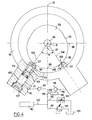
- the shaft 7 carries integrally, for example by bolting 92, inside the housing 22 and directly facing the cover 27, a cam having a mean plane 100 perpendicular to the axis 8 and advantageously constituted, in the example illustrated, by the stop plate 93 attached integrally to the shaft 7; this cam is more particularly visible in FIG. 4.
- the cam 93 is pierced right through with a bore 94 allowing the passage of the tube 72 with a clearance comparable to that authorized by the bore 73; in the direction of a radial distance from the axis 8 and in any cutting plane perpendicular to this axis, it has an outer periphery 95 of ovoid shape.
- a horizontal plane 96 including the axis 8 and fixed relative to the support 4 the shape of this periphery is indifferent provided that the cam 93 plays the role of abutment plate described above; below the plane 96, it has a circular shape with an axis 97 parallel to the axis 8 and located in the plane 14 under the axis 8, to define a cam path 98 having under the axis 8, in the plane 14, a point 99 which constitutes the point of the cam path 98 furthest from the axis 8, with a progressive decrease in the distance from the axis 8 for points of the cam path 98 more and more further from point 99, in a direction of travel of path 98 by rotation around axis 8, or in the opposite direction of travel.
- the casing flange 19 presents opposite the cam path 98 two cam touches 101 and 102 each of which is integral with the flange 19 in rotation about the axis 8 but can slide relative to the housing flange 19, radially with reference to the axis 8, so as to be able to remain at contact of the cam track 98 whatever the angular position of the arm 29 relative to the support 4, around the axis 8, within normal operating limits.
- the housing flange 19 is pierced, along respective axes 103 and 104 radial with respect to the axis 8 and situated in the plane 100, of two bores 105 and 106 each of which opens into the housing 12, towards the cam track 98, being closed opposite by a respective plug 107,108; the axes 103 and 104 are arranged symmetrically to each other with respect to a plane which merges with the vertical plane 14 in the state of static equilibrium illustrated in FIGS.
- the angular offset ⁇ is at least equal to the angular movement of the arm 29 relative to the support 4, around the axis 8, under normal conditions of use; this offset is of the order of 70 ° in the example illustrated; naturally, this figure is given only by way of nonlimiting example.
- each of the bores 105 and 106 is mounted, sliding along the axis 103, 104 of this bore, a respective piston 109, 110 that a respective compression helical spring 111, 112, interposed between this piston and the sealing plug the corresponding bore, resiliently biases towards the axis 8, so that each of the pistons 109, 110 forms a projection out of the corresponding bore 105, 106 inside the casing 22, and bears against the path cam 98 by an end surface transverse to the axis of the corresponding bore, which surface defines the cam touch 101, 102.
- This effect is used to produce a pumping of hydraulic fluid inside the casing 22 and to establish, by means of this hydraulic fluid, a pressure in the chamber 90 for biasing the braking piston 88.
- each of the pistons 109 and 1 10 is hollow and has, in the immediate vicinity of the corresponding cam touch 101, 102 a network of channels 131, 132 placed so that these channels open permanently into the housing 22 whatever the point of the cam path 98 with which contact is made with the cam feeler 101, 102 within the normal limits of use of the suspension member; inside the corresponding piston respectively, each of the networks of channels 131, 132 opens into an axial channel such as 113 provided with a non-return valve such as 114 of known structure, allowing a passage of fluid from the channels such as 131 towards the inside of the bore such as 105 via the channel such as 113, preventing passage in the opposite direction; thus, an exit movement of the piston results in the introduction, into the bore such as 105, of fluid coming from the casing 22 while a return movement of the piston in the bore causes a repression
- the conduit 115 and its counterpart 116 corresponding to the bore g e 106 comprise a respective non-return valve 117, 118 of known type, allowing the passage of fluid in the direction of a discharge from the bore 105, 106 in prohibiting passage in the opposite direction, and the two conduits 115 and 116 meet, downstream of the non-return valves 117 and 118 with reference to the direction of passage authorized, in a single conduit 119 from which, on the one hand, a conduit 120 of connection to the chamber 90, and on the other hand two conduits 121 and 122 leading in parallel to a reservoir of hydraulic fluid 123 which can be constituted by the casing 22 itself.
- the conduit 121 comprises in series an adjustable pressure relief valve 124, while the conduit 122 comprises an adjustable throttle 125 making it possible to establish through it an adjustable leakage rate the choke 125 can be advantageously controlled as a function of the pressures respectively downstream and by lover in the conduit 122 in order to suppress the influence of the viscosity of the fluid, that is to say of the temperature, on this leakage rate.
- one or the other of the pistons 109, 110 causes a supply of the conduit 119 with hydraulic fluid from of the casing 22, with a flow rate which depends on the speed of movement of the piston in its bore, that is to say on the speed of rotation of the arm relative to the support.
- This flow passing through the constriction 125, produces a pressure which is a function of the pressure drop in said constriction and which is established uniformly in the conduits 119,120,121,122 and consequently in the chamber 90, which applies to the brake linings.
- the damping force substantially proportional to the pressure prevailing in the chamber 90, itself a function of the pressure drop created at 125 by the flow of fluid in the conduit 122, tends to cancel out if this flow is canceled out, that is to say in particular when the arm 29 comes to a standstill relative to the support 4 between a rotation stroke in one direction and a rotation stroke in the other direction since the two pistons 109 and 110 are then immobile; to maintain a residual flow rate through the throttle 125 in the duct 122, that is to say prevent an almost total cancellation of the damping force, during the transient phases of reversal of the direction of rotation of the arm 29 around the axis 8 relative to the support 4, there is preferably provided a pressure accumulator 130 connected to the conduit 119 by a conduit 129; this pressure accumulator 130 is calculated to have only a negligible effect on the pressure in the chamber 90 when the arm 29 rotates around the axis 8 relative to the support 4, while possibly only playing a role of filter reducing the effects
- the cam track 98 can be given an asymmetrical shape with respect to the plane 14 with which the plane of symmetry coincides between the respective axes 103, 104 of the bores 105, 106 when the arm 29 occupies its position of static equilibrium and / or differentiate the respective sections of the pistons 109 and 110, so as to differentiate the damping force as a function of the direction of rotation of the arm 29 relative to the support 4.
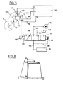
- the housing 18 carries in a solid manner a potentianetric track 140 which is thus secured to the arm 29 with respect to a rotation about the axis 8 relative to the support 4 (not illustrated in FIG. 5) and has a shape of revolution around the axis 8 with an angular development, with reference to this axis, at least equal and preferably greater than the possible angular movement of the arm 29 around the axis 8 relative to support 4 when the suspension is in service.
- the potentiometric track 140 is connected by an electrical conductor 141 to a constant voltage source integrated into a control electronics 142 which will be described later while on this track is supported, with possibility relative rotation around the axis 8 and permanent electrical contact, a sensor 143 constituted for example by a cursor, carried by the support 4, for example by means of the stop plate 93, without possibility of relative rotation around axis 8; the angular position of the sensor 143, with reference to the axis 8, on the abutment plate 93 is defined such that the sensor 143 occupies with respect to the potentiometric track 140 an angular position intermediate between the respective angular positions of the ends of this track when the suspension occupies a position of static equilibrium, and has on either side a possibility of sufficient angular movement, relative to the potentiometric track 140, so as not to leave the latter whatever the amplitude of the rotational movements of the arm 29 around the axis 8 relative to the support 4 when the suspension is in service.
- a sensor 143 constituted
- V n denotes the supply voltage of the potentiometric track 140 by the conductor 141
- the sensor 143 delivers a voltage signal V 1 which is a function of the angular position of the arm 29 relative to the support 4, with reference to axis 8.
- such a signal can be obtained by other means, and for example by optical reading of a track 144, replacing the potentiometric track 140, by means of an optical sensor 145, replacing the electrical sensor 143, or by any other type of digital encoder; although incremental type digital coders can be adopted, absolute type digital coders will be preferred, delivering either a voltage V by digital / analog conversion incorporated in the sensor, or more simply coded digital information directly representative of the angular position of the arm 29 compared to the support 4 at all times, and therefore directly usable to control a possible attitude correction.
- the signal supplied by the sensor 143 or 145 or the like is sent to the control electronics 142 which stores this signal and, if it is a signal representative of the angular position or the angular displacement of the arm 29 relative to to the support 4, the drift in a signal representative of the speed of rotation of the arm 29 relative to the support 4, with a characteristic sign of the direction of this rotation.
- the signal representative of the speed is then processed by the control electronics 142, as a function of laws memorized in the latter, to emit an electrical signal V 2 used to control a hydraulic pressure, applied to the chamber 90 of the brake by means of a pressure modulator 147 and from a source 146 of hydraulic fluid under pressure, supplied from a reservoir 148 which may advantageously be constituted by the casing 22.
- pressure modulators 147 can be used as pressure modulators 147 without departing from the scope of the present invention, provided that they make it possible to modulate a pressure as a function of an electrical signal V 2 , ie in open loop, either in closed loop with pressure copying by a pressure sensor placed near the chamber 90 for example.
- the modulator 147 could be constituted by a "pressure” servo-valve excited by the electrical signal V 2 , or also by a “flow” servo-valve provided with a pressure servo (which could advantageously be incorporated into the electronics 142) using the feedback information from the pressure sensor 156.
- the pressure modulator 147 is constituted by a slide 149 occupying at all times a position of equilibrium between the respective actions of a proportional electromagnet 150, to which the electrical signal V 2 is routed by a conductor electric 151, and of a hydraulic pressure for copying into a chamber 152 to establish in a pipe 154 leading to the chamber 90 a pressure modulated between extreme values delivered by a pipe 153 coming from the source 146 and a return pipe 155 at reservoir 148.
- the line 154 derives a line 156 for supplying the chamber 152 with feedback pressure.
- the signal V 2 controlling the movement of the slide 149 that is to say modulating the pressure in the chamber 90, is determined by the control electronics 142, as a function of the representative signal of the speed of rotation of the arm 29 around the axis 8 relative to the support 4, as well as according to laws stored in the control electronics 142 and which can be chosen at will.
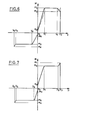
- FIG. 6 illustrates by way of nonlimiting example a mode of variation of the damping moment M (directly proportional to the damping force) as a function of the speed V of rotation of the arm 29 around the axis 8 by relative to support 4; the abscissae and positive ordinates correspond to an upward movement of the rolling member 3, relative to the support 4, while the abscissas and negative ordinates correspond to a downward movement of the rolling member 3, with respect to the support 4.
- control electronics 142 is also memorized a curve of the type illustrated, by way of nonlimiting example, in FIG. 7, namely a curve of evolution of the moment of damping M as a function of angular displacement D of the arm 29, about the axis 8, with respect to the support 4 from the position of static equilibrium;
- the abscissas and positive ordinates correspond to the case where the rotation takes place in a direction corresponding, for the rolling member 3, to a displacement above the static equilibrium position with respect to the support 4 while the abscissas and negative ordinates correspond to a movement of the arm when the rolling member 3 is below its position of static equilibrium relative to the support 4.
- a reverse evolution occurs when the amplitude of movement decreases while the rolling member 3 is above its static equilibrium position relative to the support 4.
- the values D 0 , D 1 , D 2 , D 3 , D 4 , D 5 , D 6 ' M 5 , M 6 can be predetermined at will however, preferably, MS is equal to M2 as well as M 6 is equal to M 3 .
- FIG. 8 representing the evolution of the damping lug M as a function of the speed V of rotation of the arm 29 around the axis 8 relative to the support 4 and of the amplitude D of this rotation from the static equilibrium position when the rolling member 3 moves upwards above the static equilibrium position, it being understood that similar traces could have been made as regards the movements of the rolling member 3 downwards above its static equilibrium position as well as downwards and upwards below its static equilibrium position.
- control curves as a function of the speed or the amplitude can be established, in a manner easily determinable by a person skilled in the art, to introduce filtering making the moment of damping insensitive to slow rotations, or of low amplitude, or high frequency of the arm 29 around the axis 8 relative to the support 4;
- the evolution, indicated by solid lines in FIG. 6, of the moment of damping M from the value M 1 to the value M 2 when the speed of rotation of the arm increases from the value V 2 to the value V 3 constitutes filtration against alternating rotations at high frequencies, which consist of a rapid alternation of increases in rotational speed of the arm in one direction and in the other ;
- the choice of M values 0, V. , D o for its part determines the greater or lesser sensitivity of the moment of damping to slow rotations or of low amplitude of the arm relative to the support.
- control electronics 142 for producing servos of the type indicated above, or of other types is within the scope of their normal abilities.
- these elements are permanently lubricated and cooled.
- means may advantageously be provided to ensure that, despite the momentary withdrawals of the hydraulic fluid in the casing and the movement of the piston 47 in the jacket 44, and whatever the temperature to which this fluid is brought, the casing 22 is filled to the maximum with hydraulic fluid at least in certain angular positions of the arm relative to the support, under normal conditions of use.
- a bladder 126 made of flexible, tight, elastically extensible material, which bladder contains a gas under pressure which, like the compressible fluid housed in chambers 56 and 42, may be advantageous. ment consist of nitrogen; particularly advantageously, this bladder was placed in the chamber '1 delimited, inside the cavity 32, by the partition 40, so that due to such positioning, the variations in volume of the bladder 126 cause the circulation of the hydraulic fluid in the housing 22 in the immediate vicinity of the brake linings 84 and sectors of the brake discs 82.
- the bladder 126 could be supplemented or replaced by accumulator means of the same function, arranged in an appropriate manner.
Landscapes
- Engineering & Computer Science (AREA)
- Chemical & Material Sciences (AREA)
- Combustion & Propulsion (AREA)
- Transportation (AREA)
- Mechanical Engineering (AREA)
- Vehicle Body Suspensions (AREA)
Applications Claiming Priority (2)
| Application Number | Priority Date | Filing Date | Title |
|---|---|---|---|
| FR8513935 | 1985-09-19 | ||
| FR8513935A FR2587279B1 (fr) | 1985-09-19 | 1985-09-19 | Organe de suspension pour vehicule, avec moyens d'amortissement |
Publications (1)
| Publication Number | Publication Date |
|---|---|
| EP0218509A1 true EP0218509A1 (de) | 1987-04-15 |
Family
ID=9323080
Family Applications (1)
| Application Number | Title | Priority Date | Filing Date |
|---|---|---|---|
| EP86402034A Withdrawn EP0218509A1 (de) | 1985-09-19 | 1986-09-17 | Federungsaggregat für Fahrzeuge mit Dämpfungsmittel |
Country Status (5)
| Country | Link |
|---|---|
| US (1) | US4721327A (de) |
| EP (1) | EP0218509A1 (de) |
| BR (1) | BR8604481A (de) |
| ES (1) | ES2002357A6 (de) |
| FR (1) | FR2587279B1 (de) |
Families Citing this family (12)
| Publication number | Priority date | Publication date | Assignee | Title |
|---|---|---|---|---|
| US5183287A (en) * | 1991-07-30 | 1993-02-02 | General Dynamics Land Systems, Inc. | Suspension system for road wheel of a track laying vehicle |
| SE516438C2 (sv) * | 2000-06-06 | 2002-01-15 | Haegglunds Vehicle Ab | Anordning för dämpning av svängningsrörelser hos en hjulbärande pendelarm för motorfordon |
| US7273117B2 (en) * | 2003-05-15 | 2007-09-25 | General Dynamics Land Systems, Inc. | Vehicle suspension apparatus |
| US20050205329A1 (en) * | 2004-02-25 | 2005-09-22 | Shimon Fanger-Vexler | Vehicle and vehicle drive-through suspension arm |
| US7963537B2 (en) * | 2009-03-17 | 2011-06-21 | Horstman Defence Systems Limited | Suspension unit |
| EP2440902A2 (de) * | 2009-06-11 | 2012-04-18 | Eaton Corporation | Fehlererkennung und -aufhebung in einem hybridantriebssystem |
| GB2480629A (en) | 2010-05-25 | 2011-11-30 | Horstman Defence Systems Ltd | A retaining mechanism for retaining a vehicle suspension arm in a raisd position |
| GB2480631B (en) | 2010-05-25 | 2016-06-22 | Horstman Defence Systems Ltd | Suspension unit |
| GB2480630A (en) | 2010-05-25 | 2011-11-30 | Horstman Defence Systems Ltd | A suspension unit for use on a tracked vehicle |
| US10166828B2 (en) | 2014-11-07 | 2019-01-01 | Mitsubishi Heavy Industries, Ltd. | Suspension device for amphibious vehicle |
| DE102015103556A1 (de) * | 2015-03-11 | 2016-09-15 | Manitowoc Crane Group France Sas | Vorrichtung und Verfahren zur Bestimmung der Bodendruckverteilung bei einer mobilen Arbeitsmaschine |
| KR20250004843A (ko) * | 2022-04-20 | 2025-01-08 | 피에드라피타 시스템즈 에스.엘. | 유공압 회전식 서스펜션 |
Citations (3)
| Publication number | Priority date | Publication date | Assignee | Title |
|---|---|---|---|---|
| US3047283A (en) * | 1958-05-01 | 1962-07-31 | Monroe Auto Equipment Co | Fluid actuated frictional damping device |
| US3521527A (en) * | 1966-03-28 | 1970-07-21 | Houdaille Industries Inc | Rotary vane suspension units for endless track vehicles and the like |
| EP0090154A2 (de) * | 1982-03-25 | 1983-10-05 | Ex-Cell-O Corporation | Radaufhängung |
-
1985
- 1985-09-19 FR FR8513935A patent/FR2587279B1/fr not_active Expired
-
1986
- 1986-09-17 EP EP86402034A patent/EP0218509A1/de not_active Withdrawn
- 1986-09-18 BR BR8604481A patent/BR8604481A/pt unknown
- 1986-09-19 US US06/909,831 patent/US4721327A/en not_active Expired - Lifetime
- 1986-09-19 ES ES8602007A patent/ES2002357A6/es not_active Expired
Patent Citations (3)
| Publication number | Priority date | Publication date | Assignee | Title |
|---|---|---|---|---|
| US3047283A (en) * | 1958-05-01 | 1962-07-31 | Monroe Auto Equipment Co | Fluid actuated frictional damping device |
| US3521527A (en) * | 1966-03-28 | 1970-07-21 | Houdaille Industries Inc | Rotary vane suspension units for endless track vehicles and the like |
| EP0090154A2 (de) * | 1982-03-25 | 1983-10-05 | Ex-Cell-O Corporation | Radaufhängung |
Also Published As
| Publication number | Publication date |
|---|---|
| FR2587279B1 (fr) | 1989-08-11 |
| ES2002357A6 (es) | 1988-08-01 |
| BR8604481A (pt) | 1987-05-19 |
| FR2587279A1 (fr) | 1987-03-20 |
| US4721327A (en) | 1988-01-26 |
Similar Documents
| Publication | Publication Date | Title |
|---|---|---|
| EP0220094B1 (de) | Federungsaggregat mit Schwingenarm für Fahrzeuge | |
| EP0218509A1 (de) | Federungsaggregat für Fahrzeuge mit Dämpfungsmittel | |
| EP0304599A1 (de) | Mit Mitteln zur Änderung der Dämpfungscharakteristik ausgerüsteter hydraulischer Stossdämpfer | |
| EP1979591B1 (de) | Druckvorrichtung für einen motor mit variabler verdichtung | |
| BE1006281A3 (fr) | Changement de vitesse a organe de transmission sur flasques coniques. | |
| EP0234157A1 (de) | Umlaufender Dämpfer | |
| FR2528140A1 (fr) | Amortisseur du type fluidique | |
| FR2501784A1 (fr) | Moteur a mouvement lineaire et plateau oscillant pour un tel moteur | |
| FR2657821A1 (de) | ||
| EP0554147A1 (de) | Aufhängungseinheit für ein schweres Fahrzeug, insbesondere für ein Gleiskettenfahrzeug | |
| EP0942103B1 (de) | Ventileinrichtung für einen hydraulischen Motor zum Antreiben einer Masse grossens Trägheitsvermögens | |
| EP0453847A1 (de) | Vorrichtung zur axialen Verschiebung von Walzen in einer Druckmaschine | |
| EP0052387B1 (de) | Motor mit mindestens einem linearbewegten Kolben und einerTaumelscheibe | |
| FR2503273A1 (fr) | Pompe hydraulique | |
| CA1063388A (fr) | Dispositifs de transmission de vitesse | |
| EP1072791B1 (de) | Radialkolbenmotor mit einer einzigen Koppelauswahlvorrichtung | |
| EP0065084B1 (de) | Vorrichtung zum Steuern der Bewegung einer oszillierenden Schurre und mit dieser Vorrichtung versehene Schachtofenbeschickungsanlage | |
| EP0219393A1 (de) | Federungsaggregat für Fahrzeuge mit Niveauregulierung | |
| FR2512511A1 (fr) | Perfectionnements aux organes de variation de rapport de transmission | |
| EP0176381B1 (de) | Hydraulisches Hochdruckwegeventil mit Vorsteuerdruckerzeuger | |
| EP0170572A1 (de) | Hydrostatische Trageinrichtung | |
| FR2503055A1 (fr) | Suspension pour vehicule | |
| FR2607891A1 (fr) | Amortisseur rotatif | |
| FR2516619A1 (fr) | Procede d'amortissement de mouvements oscillants en particulier pour tres lourdes charges et dispositif pour la mise en oeuvre de ce procede | |
| EP2261588B1 (de) | Lagerungsvorrichtung eines Geschützturms |
Legal Events
| Date | Code | Title | Description |
|---|---|---|---|
| PUAI | Public reference made under article 153(3) epc to a published international application that has entered the european phase |
Free format text: ORIGINAL CODE: 0009012 |
|
| AK | Designated contracting states |
Kind code of ref document: A1 Designated state(s): DE FR GB IT |
|
| 17P | Request for examination filed |
Effective date: 19870316 |
|
| 17Q | First examination report despatched |
Effective date: 19871127 |
|
| STAA | Information on the status of an ep patent application or granted ep patent |
Free format text: STATUS: THE APPLICATION IS DEEMED TO BE WITHDRAWN |
|
| 18D | Application deemed to be withdrawn |
Effective date: 19910813 |
|
| RIN1 | Information on inventor provided before grant (corrected) |
Inventor name: CHAMBON, CLAUDE ANDRE Inventor name: CHAUVEAU, JEAN-MARC |