EP0453847A1 - Vorrichtung zur axialen Verschiebung von Walzen in einer Druckmaschine - Google Patents
Vorrichtung zur axialen Verschiebung von Walzen in einer Druckmaschine Download PDFInfo
- Publication number
- EP0453847A1 EP0453847A1 EP91105492A EP91105492A EP0453847A1 EP 0453847 A1 EP0453847 A1 EP 0453847A1 EP 91105492 A EP91105492 A EP 91105492A EP 91105492 A EP91105492 A EP 91105492A EP 0453847 A1 EP0453847 A1 EP 0453847A1
- Authority
- EP
- European Patent Office
- Prior art keywords
- cylinder
- chamber
- piston
- ride
- central shaft
- Prior art date
- Legal status (The legal status is an assumption and is not a legal conclusion. Google has not performed a legal analysis and makes no representation as to the accuracy of the status listed.)
- Withdrawn
Links
Images


Classifications
-
- B—PERFORMING OPERATIONS; TRANSPORTING
- B41—PRINTING; LINING MACHINES; TYPEWRITERS; STAMPS
- B41F—PRINTING MACHINES OR PRESSES
- B41F31/00—Inking arrangements or devices
- B41F31/15—Devices for moving vibrator-rollers
-
- Y—GENERAL TAGGING OF NEW TECHNOLOGICAL DEVELOPMENTS; GENERAL TAGGING OF CROSS-SECTIONAL TECHNOLOGIES SPANNING OVER SEVERAL SECTIONS OF THE IPC; TECHNICAL SUBJECTS COVERED BY FORMER USPC CROSS-REFERENCE ART COLLECTIONS [XRACs] AND DIGESTS
- Y10—TECHNICAL SUBJECTS COVERED BY FORMER USPC
- Y10S—TECHNICAL SUBJECTS COVERED BY FORMER USPC CROSS-REFERENCE ART COLLECTIONS [XRACs] AND DIGESTS
- Y10S101/00—Printing
- Y10S101/38—Means for axially reciprocating inking rollers
Definitions
- the present invention relates to a device for axial movement of strolls in a printing machine.
- the object of the present invention is to provide a device for moving all the strolls of a printing machine, a device the control of which can be easily done remotely and without having to stop the machine.
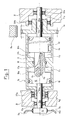
- Figure 1 shows a first ride N1 of a printing machine which may include four.
- the N1 travel consists of a fixed central shaft 12 and a hollow outer cylinder 11 movable parallel to the axis 10a of the N1 travel, the cylinder 11 being concentric with the central shaft 12.
- the outer cylinder 11 is extended by a hollow shaft end 11a, respectively 11b, penetrating with a little radial clearance in the bores 20a and 20b of the frame B, thus forming a dust protection for the bearings 21a, 21b, 26a, 26b.
- the cylinder 11 is provided, at least at one end, with a toothed ring 13 which can come into engagement with a toothed drive wheel R e of the machine.
- the teeth of the wheel R e are wider than those of the crown 13 to ensure the drive of the cylinder 11 when it moves from left to right and vice versa in order to homogenize the distribution of the ink on the distributor roller correspondent, as is known.
- Each end 12a, respectively 12b, of the central shaft 12 is mounted in rotation, by means of bearings, 21a, respectively 21b, in the frame B.
- the central shaft 12, axially fixed, is linked in rotation, to using a key 14, with the outer cylinder 11.
- the key 14, fixed to the cylinder 11 is in engagement and in free sliding with a groove 15 of the central shaft 12 to allow a relative axial movement between the cylinder hollow 11 and the central shaft 12.
- Each end 12a, 12b of the central shaft 12 passes through the end of the hollow shaft 11a, 11b respectively.
- a translation sleeve 26a, 26b is interposed between each end 12a, 12b of the central shaft 12 and the corresponding hollow axis 11a, 11b.
- each chamber C1, C2 has a first wall 16a, 16b constituted by a transverse shoulder, that is to say perpendicular to the axis 10a, of the central shaft 12, and by a second wall 17a, respectively 17b constituted by a transverse shoulder of the cylinder 11.
- Seals 18 ensure the sealing of the two chambers C1, C2.
- Inside the central shaft 12 are provided two conduits A1, A2 one of which A1 is connected to the chamber C1, and the other A2 to the chamber C2.
- the two conduits A1, A2 pass through a rotary joint 19 situated at the free end of the end 12a of the central shaft 12.
- the conduit A1 is connected, as shown in the diagram of FIG. 2, to using an external conduit D1 , to the first chamber B1 of a main cylinder M, and the conduit A2 is connected, by an external conduit D2 , to the second chamber C2 of a second ride N2 identical to that shown in figure 1.
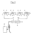
- FIG. 2 shows the hydraulic diagram of the movement control for four trips N1 to N4, all similar to those shown in Figure 1.
- the hydraulic control system comprises a master cylinder or main cylinder M provided with two chambers B1, B2 separated from each other by a movable piston P.
- the piston P is extended outside by two rods P1, P2.
- a rod P2 is connected to the free end of a lever 80 which can rock around a pivot 81.
- the lever 80 is connected to a drive 82 intended for rocking the lever 80 around the pivot 81.
- the pivot 81 is mounted on a screw socket system 84 so as to be able to adjust the position of pivot 81 relative to lever 80 and thus vary the amplitude of the stroke of piston P.
- the other rod P2 is used to obtain same displacements of oil volumes, during the back-and-forth movement of the piston P.
- the first chamber B1 of the main cylinder M is directly connected, by an external duct D1, to the duct A1 of the first chamber C1 of the first N1 ride.
- the second chamber C2 of the ride N1 is connected, by its conduit A2 and an outer conduit D2, to the conduit A2 of the ride N2, the first chamber C1 of which is connected, by its conduit A1 and an outer conduit D3, to the conduit A2 of the second room C2 of the third ride N3.
- the first chamber C1 of the third ride N3 is connected, by its conduit A1 and an external conduit D4, to the conduit A1 of the first chamber C1 of the fourth ride N4 whose second chamber C2 is connected, by its conduit A2 and a conduit outside D5, to the second chamber B2 of the main cylinder M.
- the drive 82 can, for example, be carried out with a cam, or an eccentric or other lever systems.
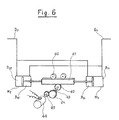
- rollers 60 serving as a support and guide, a rack 61, a pinion 62, a shaft 63, reduction gears 64, 65 and a motor 66.
- the main cylinder M is in the form of two cylinders M1, M2 standard trade.
- each pair of chambers C1, C2 of the stretches Nades to N4 is part of a cylinder whose output rod of the piston must act, against a force F representing the force necessary for the displacement of the outer cylinder 11 of each ride N1 to N4,
- the closed-loop hydraulic circuit described above is of the cascade type in which the hydraulic pressure is added; consequently, if a pressure difference of 1P between the two chambers C1 and C2 of each ride N1 to N4 is necessary, the pressure in the chamber C1 of the last ride N4, and therefore also in the second chamber B2 of the main cylinder M, will be 4P. It is clear that this is a high pressure and that leaks would be detrimental to the operation of the system.
- a hydraulic booster system that is to say a pressure relief system ( Figure 4).
- a system comprises, in known manner, a motor M2, a pump Po, an oil tank Rh with filling means E provided with a filter Fi and with a level control N7, a pressure limiter Lp, an accumulator Ac and a pressure switch Ps.
- a pressurization system makes it possible, when the printing unit is stopped, that is to say at rest of the N1 to N4 rides, to compensate for oil leaks, that would have occurred in the closed loop hydraulic circuit, restoring the basic or machine shutdown pressure.
- the re-pressure system is connected, by a duct D6 to the outer ducts D1, D3, D5 of each printing unit of the machine.
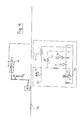
- x represents the distance between the movable wall 17a, or 17b, of the cylinder and a fixed element (for example the valve S1, or S2) against which this wall could abut
- the valves S1, S2 are produced so that a decreasing the distance x below a value y previously set (at the factory) causes displacement of the pistons T1, T2 in the direction of the opening of the first orifices O1, O2.
- the hollow cylinder 11 On the internal periphery of the hollow cylinder 11 are mounted two stops G1, G2, one of which G1 can, at the end of the cylinder 11 travel to the right, come to act on the piston T1 to open the orifice O1; conversely, at the end of stroke of the cylinder 11 to the left, the other stop G2 can act on the piston T2 to open the orifice O2.
- FIG. 5 shows the instant when the cylinder 11 is at the end of its travel to the right, in the direction of the arrow F.
- the piston T1 pushed to the right by the stop G1 is no longer in contact with the seal 91. Since at this instant the pressure in the chamber C2 is higher than that of the chamber C1, as well as that of the common conduit 92 and of the internal volume with spring 90 of the valve S2, the piston T2 will move to the left, which causes, via the common conduit 92, a rebalancing of the pressures in the two chambers C1, C2. At this time, the displacement of the cylinder 11 is therefore completed.
- the next movement of the cylinder 11 to the left can begin with the establishment of an overpressure generated in the chamber C1, by displacement of the piston P of the main cylinder M to the left.
- the stops G1, G2 are schematically represented in the form of a cam with two ramps mounted on the cylinder 11 and actuating the outlet rod of the valves S1, S2.
- the chambers drawn over the entire active width of the ride in Figure 1 can be and will advantageously be concentrated in the left end of it, since the axial strokes are around ⁇ 20 mm (as shown in dashed lines). This allows to use almost all the ride for cooling, largely customary equipment and whose swivel joint will be at the end opposite to 19. (The construction according to Figure 5 will already take into account the previous remark).
Landscapes
- Inking, Control Or Cleaning Of Printing Machines (AREA)
- Supply Devices, Intensifiers, Converters, And Telemotors (AREA)
- Rotary Presses (AREA)
Applications Claiming Priority (2)
| Application Number | Priority Date | Filing Date | Title |
|---|---|---|---|
| CH1366/90 | 1990-04-23 | ||
| CH1366/90A CH682895A5 (fr) | 1990-04-23 | 1990-04-23 | Dispositif de déplacement des baladeurs dans une machine d'impression. |
Publications (1)
| Publication Number | Publication Date |
|---|---|
| EP0453847A1 true EP0453847A1 (de) | 1991-10-30 |
Family
ID=4208746
Family Applications (1)
| Application Number | Title | Priority Date | Filing Date |
|---|---|---|---|
| EP91105492A Withdrawn EP0453847A1 (de) | 1990-04-23 | 1991-04-08 | Vorrichtung zur axialen Verschiebung von Walzen in einer Druckmaschine |
Country Status (5)
| Country | Link |
|---|---|
| US (1) | US5134939A (de) |
| EP (1) | EP0453847A1 (de) |
| JP (1) | JPH04224957A (de) |
| CA (1) | CA2040954C (de) |
| CH (1) | CH682895A5 (de) |
Cited By (8)
| Publication number | Priority date | Publication date | Assignee | Title |
|---|---|---|---|---|
| EP0476379A1 (de) * | 1990-09-21 | 1992-03-25 | Rockwell International Corporation | Oszillator zum axialen Hin- und Herbewegen einer Walze |
| EP0616887A1 (de) * | 1993-03-24 | 1994-09-28 | Komori-Chambon Sa | Rakelvorrichtung für eine Tiefdruckmaschine |
| DE19603765A1 (de) * | 1996-02-02 | 1997-08-07 | Heidelberger Druckmasch Ag | Vorrichtung zum axialen Bewegen einer Reibwalze |
| DE102006042959A1 (de) * | 2006-05-17 | 2007-11-22 | Koenig & Bauer Aktiengesellschaft | Verfahren und Vorrichtung zum Reduzieren von Schwingungen eines rotierenden Zylinders einer Druckmaschine |
| WO2007128709A3 (de) * | 2006-05-10 | 2008-01-31 | Koenig & Bauer Ag | Walze einer druckmaschine mit einer vorrichtung zum erzeugen einer axialen oszillationsbewegung der rotierenden walze |
| DE102017215920A1 (de) | 2017-09-08 | 2019-03-14 | Koenig & Bauer Ag | Changierbare Walze sowie Druckmaschine mit mehreren Druckwerken mit einer derartigen Walze |
| WO2019048088A1 (de) | 2017-09-08 | 2019-03-14 | Koenig & Bauer Ag | Changierbare walze sowie druckmaschine mit mehreren druckwerken mit einer derartigen walze |
| DE102018200333A1 (de) | 2018-01-11 | 2019-07-11 | Koenig & Bauer Ag | Changierbare Walze sowie Druckmaschine mit mehreren Druckwerken mit einer derartigen Walze |
Families Citing this family (8)
| Publication number | Priority date | Publication date | Assignee | Title |
|---|---|---|---|---|
| DE4140048C2 (de) * | 1991-12-05 | 1995-09-21 | Roland Man Druckmasch | Farbwerk einer Druckmaschine, insbesondere Bogenoffsetdruckmaschine |
| US5411462A (en) * | 1993-08-30 | 1995-05-02 | Link; Terry G. | Lightweight ink transfer roll |
| DE19756077A1 (de) * | 1997-12-17 | 1999-06-24 | Heidelberger Druckmasch Ag | Verfahren zum Betrieb einer Rotationsdruckmaschine und Vorrichtung in einer Rotationsdruckmaschine |
| US6672206B2 (en) * | 2002-01-04 | 2004-01-06 | Graphic Specialists, Inc. | Form roller for printing press |
| JP2007309508A (ja) * | 2006-04-20 | 2007-11-29 | Kinyosha Co Ltd | 揺動ローラー、転がり軸受、ローラーの揺動方法 |
| US7931362B2 (en) * | 2007-07-13 | 2011-04-26 | Xerox Corporation | System for controlling engagement of a transfix roller with an image receiving member in a printer |
| DE102007049916A1 (de) | 2007-10-18 | 2009-04-23 | Heidelberger Druckmaschinen Ag | Verfahren zum Betreiben eines Druckwerks einer Druckmaschine |
| FI20235243A1 (en) * | 2023-02-28 | 2024-08-29 | Etteplan Oyj | PREVENTION OF INDUSTRIAL ROLLER VIBRATION |
Citations (8)
| Publication number | Priority date | Publication date | Assignee | Title |
|---|---|---|---|---|
| US3013489A (en) * | 1957-10-01 | 1961-12-19 | Samuel M Langston Co | Printing machine ink roll vibrator |
| US3179047A (en) * | 1963-07-29 | 1965-04-20 | George O Comeau | Oscillating ink rolls |
| FR1418944A (fr) * | 1964-10-13 | 1965-11-26 | Rouleau distributeur à va-et-vient pour encres, vernis et autres produits analogues | |
| GB1331849A (en) * | 1971-11-10 | 1973-09-26 | Polygraph Leipzig | Printing machine including a device for producing axial movement of axially reciprocable rubbing rollers of inking and damping units in the printing machine |
| FR2283780A1 (fr) * | 1974-09-04 | 1976-04-02 | Schulz Juergen | Dispositif d'encrage pour machine a imprimer |
| FR2284451A1 (fr) * | 1974-09-11 | 1976-04-09 | Roland Offsetmaschf | Perfectionnements aux dispositifs d'encrage sur les presses d'impression |
| US4205605A (en) * | 1978-03-13 | 1980-06-03 | Roland Offsetmaschinenfabrik Faber & Schleicher Ag | Device for determination of operating angle of distributor rollers |
| EP0363228A2 (de) * | 1988-10-07 | 1990-04-11 | Advanced Graphics Technologies, Inc. | Druckmaschinenwalzen |
Family Cites Families (2)
| Publication number | Priority date | Publication date | Assignee | Title |
|---|---|---|---|---|
| IT1157048B (it) * | 1982-06-14 | 1987-02-11 | Fiat Allis Europ | Circuito idraulico per l'alimentazione di fluido in pressione ad una pluralita di camere utilizzatrici provvisto di mezzi selezionatori per l'alimentazione prioritaria di una o piu delle suddette camere utilizzatrici |
| JP2519504B2 (ja) * | 1988-04-09 | 1996-07-31 | テクノロール株式会社 | オフセツト印刷機 |
-
1990
- 1990-04-23 CH CH1366/90A patent/CH682895A5/fr not_active IP Right Cessation
-
1991
- 1991-04-08 EP EP91105492A patent/EP0453847A1/de not_active Withdrawn
- 1991-04-22 CA CA002040954A patent/CA2040954C/en not_active Expired - Fee Related
- 1991-04-23 JP JP3092097A patent/JPH04224957A/ja active Pending
- 1991-11-22 US US07/798,825 patent/US5134939A/en not_active Expired - Lifetime
Patent Citations (8)
| Publication number | Priority date | Publication date | Assignee | Title |
|---|---|---|---|---|
| US3013489A (en) * | 1957-10-01 | 1961-12-19 | Samuel M Langston Co | Printing machine ink roll vibrator |
| US3179047A (en) * | 1963-07-29 | 1965-04-20 | George O Comeau | Oscillating ink rolls |
| FR1418944A (fr) * | 1964-10-13 | 1965-11-26 | Rouleau distributeur à va-et-vient pour encres, vernis et autres produits analogues | |
| GB1331849A (en) * | 1971-11-10 | 1973-09-26 | Polygraph Leipzig | Printing machine including a device for producing axial movement of axially reciprocable rubbing rollers of inking and damping units in the printing machine |
| FR2283780A1 (fr) * | 1974-09-04 | 1976-04-02 | Schulz Juergen | Dispositif d'encrage pour machine a imprimer |
| FR2284451A1 (fr) * | 1974-09-11 | 1976-04-09 | Roland Offsetmaschf | Perfectionnements aux dispositifs d'encrage sur les presses d'impression |
| US4205605A (en) * | 1978-03-13 | 1980-06-03 | Roland Offsetmaschinenfabrik Faber & Schleicher Ag | Device for determination of operating angle of distributor rollers |
| EP0363228A2 (de) * | 1988-10-07 | 1990-04-11 | Advanced Graphics Technologies, Inc. | Druckmaschinenwalzen |
Cited By (14)
| Publication number | Priority date | Publication date | Assignee | Title |
|---|---|---|---|---|
| EP0476379A1 (de) * | 1990-09-21 | 1992-03-25 | Rockwell International Corporation | Oszillator zum axialen Hin- und Herbewegen einer Walze |
| EP0616887A1 (de) * | 1993-03-24 | 1994-09-28 | Komori-Chambon Sa | Rakelvorrichtung für eine Tiefdruckmaschine |
| FR2702995A1 (fr) * | 1993-03-24 | 1994-09-30 | Komori Chambon | Dispositif de raclage pour un appareil d'impression héliographique. |
| DE19603765A1 (de) * | 1996-02-02 | 1997-08-07 | Heidelberger Druckmasch Ag | Vorrichtung zum axialen Bewegen einer Reibwalze |
| CN101432140B (zh) * | 2006-05-10 | 2010-07-28 | 柯尼格及包尔公开股份有限公司 | 带有用于产生旋转辊轴向振动的装置的印刷机辊 |
| WO2007128709A3 (de) * | 2006-05-10 | 2008-01-31 | Koenig & Bauer Ag | Walze einer druckmaschine mit einer vorrichtung zum erzeugen einer axialen oszillationsbewegung der rotierenden walze |
| US8001894B2 (en) | 2006-05-10 | 2011-08-23 | Koenig & Bauer Aktiengesellschaft | Roller of a printing machine comprising a device for generating an axial oscillating movement of the rotating roller |
| DE102006042959A1 (de) * | 2006-05-17 | 2007-11-22 | Koenig & Bauer Aktiengesellschaft | Verfahren und Vorrichtung zum Reduzieren von Schwingungen eines rotierenden Zylinders einer Druckmaschine |
| DE102006042959B4 (de) * | 2006-05-17 | 2012-06-06 | Officine Meccaniche Giovanni Cerutti S.P.A. | Verfahren und Vorrichtung zum Reduzieren von Schwingungen eines rotierenden Zylinders einer Druckmaschine |
| DE102017215920A1 (de) | 2017-09-08 | 2019-03-14 | Koenig & Bauer Ag | Changierbare Walze sowie Druckmaschine mit mehreren Druckwerken mit einer derartigen Walze |
| WO2019048088A1 (de) | 2017-09-08 | 2019-03-14 | Koenig & Bauer Ag | Changierbare walze sowie druckmaschine mit mehreren druckwerken mit einer derartigen walze |
| US11186079B2 (en) | 2017-09-08 | 2021-11-30 | Koenig & Bauer Ag | Oscillating roller and printing press having a plurality of printing units that have such a roller |
| DE102017215920B4 (de) | 2017-09-08 | 2025-03-13 | Koenig & Bauer Ag | Changierbare Walze sowie Druckmaschine mit mehreren Druckwerken mit einer derartigen Walze |
| DE102018200333A1 (de) | 2018-01-11 | 2019-07-11 | Koenig & Bauer Ag | Changierbare Walze sowie Druckmaschine mit mehreren Druckwerken mit einer derartigen Walze |
Also Published As
| Publication number | Publication date |
|---|---|
| CA2040954A1 (en) | 1991-10-24 |
| CH682895A5 (fr) | 1993-12-15 |
| US5134939A (en) | 1992-08-04 |
| JPH04224957A (ja) | 1992-08-14 |
| CA2040954C (en) | 1994-08-09 |
Similar Documents
| Publication | Publication Date | Title |
|---|---|---|
| EP0453847A1 (de) | Vorrichtung zur axialen Verschiebung von Walzen in einer Druckmaschine | |
| EP0388244B1 (de) | Kupplung für die Übertragung von alternierenden Kräftepaaren | |
| FR2662215A1 (fr) | Dispositif de compression, en particulier pour le remplissage sous pression d'un reservoir. | |
| EP0220094B1 (de) | Federungsaggregat mit Schwingenarm für Fahrzeuge | |
| FR2548263A1 (fr) | Mecanisme a dispositif de protection contre des surcharges, notamment pour l'entrainement de rabots a charbon et analogues | |
| FR2714441A1 (fr) | Dispositif d'actionnement à gradins. | |
| EP0636788B1 (de) | Kolbenförderpumpe durch eine hin- und hergehende Bewegung angetrieben | |
| EP0217699B1 (de) | Motorvorrichtung des Kolbenflüssigkeitsmessertyps, insbesondere für eine Dosierpumpe | |
| EP0500419B1 (de) | Proportionales Wegeventil und Steuersystem für mehrere hydraulische Verbrauchen, wobei jeder solch ein Ventil beinhaltet | |
| EP0218509A1 (de) | Federungsaggregat für Fahrzeuge mit Dämpfungsmittel | |
| FR2551144A1 (fr) | Commande de compensation de baisse de vitesse d'une pompe a cylindree variable reliee a un moteur | |
| CH618660A5 (de) | ||
| EP0428192B1 (de) | Stufenloses hydrostatisches Radialkolbengetriebe | |
| FR2529129A1 (fr) | Machine pour l'usinage de vilebrequins | |
| FR2578019A1 (fr) | Soupape a tambour de commande de transmission pour une transmission a rouleaux de traction infiniment variable du type toroidal | |
| EP0852306B1 (de) | Regelbarer, hydraulischer Getriebemotor | |
| CH683606A5 (fr) | Dispositif avec vérin à précontrainte de contrôle de la pression de travail entre deux cylindres rotatifs coatifs dans une machine de traitement de matière en bande. | |
| FR2700811A1 (fr) | Dispositif pour générer une pression variable au sein d'un liquide. | |
| EP0513882B1 (de) | Volumetrisches System zum Messen des Durchflusses einer Flüssigkeit | |
| FR2625514A1 (fr) | Modulateur pour commander des mecaniques d'armure tournant a tres grande vitesse | |
| BE443167A (de) | ||
| EP0039643A1 (de) | Fluid-Sicherheitsventil | |
| FR2699609A1 (fr) | Procédé et dispositif pour la mise en mouvement ou l'arrêt d'un moteur hydraulique entraînant un ensemble présentant une grande inertie. | |
| FR2701067A1 (fr) | Moyen mécanique de commande effectuant un déplacement linéaire unidirectionnel et moyen suiveur effectuant un déplacement alternatif et système de commande de direction arrière de véhicule automobile. | |
| EP0616887A1 (de) | Rakelvorrichtung für eine Tiefdruckmaschine |
Legal Events
| Date | Code | Title | Description |
|---|---|---|---|
| PUAI | Public reference made under article 153(3) epc to a published international application that has entered the european phase |
Free format text: ORIGINAL CODE: 0009012 |
|
| 17P | Request for examination filed |
Effective date: 19910408 |
|
| AK | Designated contracting states |
Kind code of ref document: A1 Designated state(s): AT BE DE DK ES FR GB IT LU NL SE |
|
| 17Q | First examination report despatched |
Effective date: 19930831 |
|
| STAA | Information on the status of an ep patent application or granted ep patent |
Free format text: STATUS: THE APPLICATION HAS BEEN WITHDRAWN |
|
| 18W | Application withdrawn |
Withdrawal date: 19931115 |