EP0218546A1 - Vorrichtung für die Mikropositionierung - Google Patents
Vorrichtung für die Mikropositionierung Download PDFInfo
- Publication number
- EP0218546A1 EP0218546A1 EP86810382A EP86810382A EP0218546A1 EP 0218546 A1 EP0218546 A1 EP 0218546A1 EP 86810382 A EP86810382 A EP 86810382A EP 86810382 A EP86810382 A EP 86810382A EP 0218546 A1 EP0218546 A1 EP 0218546A1
- Authority
- EP
- European Patent Office
- Prior art keywords
- guide means
- micro
- positioning device
- actuator
- reference base
- Prior art date
- Legal status (The legal status is an assumption and is not a legal conclusion. Google has not performed a legal analysis and makes no representation as to the accuracy of the status listed.)
- Granted
Links
Images

Classifications
-
- G—PHYSICS
- G03—PHOTOGRAPHY; CINEMATOGRAPHY; ANALOGOUS TECHNIQUES USING WAVES OTHER THAN OPTICAL WAVES; ELECTROGRAPHY; HOLOGRAPHY
- G03F—PHOTOMECHANICAL PRODUCTION OF TEXTURED OR PATTERNED SURFACES, e.g. FOR PRINTING, FOR PROCESSING OF SEMICONDUCTOR DEVICES; MATERIALS THEREFOR; ORIGINALS THEREFOR; APPARATUS SPECIALLY ADAPTED THEREFOR
- G03F7/00—Photomechanical, e.g. photolithographic, production of textured or patterned surfaces, e.g. printing surfaces; Materials therefor, e.g. comprising photoresists; Apparatus specially adapted therefor
- G03F7/70—Microphotolithographic exposure; Apparatus therefor
- G03F7/70691—Handling of masks or workpieces
- G03F7/70716—Stages
-
- B—PERFORMING OPERATIONS; TRANSPORTING
- B23—MACHINE TOOLS; METAL-WORKING NOT OTHERWISE PROVIDED FOR
- B23Q—DETAILS, COMPONENTS, OR ACCESSORIES FOR MACHINE TOOLS, e.g. ARRANGEMENTS FOR COPYING OR CONTROLLING; MACHINE TOOLS IN GENERAL CHARACTERISED BY THE CONSTRUCTION OF PARTICULAR DETAILS OR COMPONENTS; COMBINATIONS OR ASSOCIATIONS OF METAL-WORKING MACHINES, NOT DIRECTED TO A PARTICULAR RESULT
- B23Q1/00—Members which are comprised in the general build-up of a form of machine, particularly relatively large fixed members
- B23Q1/25—Movable or adjustable work or tool supports
- B23Q1/26—Movable or adjustable work or tool supports characterised by constructional features relating to the co-operation of relatively movable members; Means for preventing relative movement of such members
- B23Q1/34—Relative movement obtained by use of deformable elements, e.g. piezoelectric, magnetostrictive, elastic or thermally-dilatable elements
- B23Q1/36—Springs
-
- B—PERFORMING OPERATIONS; TRANSPORTING
- B23—MACHINE TOOLS; METAL-WORKING NOT OTHERWISE PROVIDED FOR
- B23Q—DETAILS, COMPONENTS, OR ACCESSORIES FOR MACHINE TOOLS, e.g. ARRANGEMENTS FOR COPYING OR CONTROLLING; MACHINE TOOLS IN GENERAL CHARACTERISED BY THE CONSTRUCTION OF PARTICULAR DETAILS OR COMPONENTS; COMBINATIONS OR ASSOCIATIONS OF METAL-WORKING MACHINES, NOT DIRECTED TO A PARTICULAR RESULT
- B23Q1/00—Members which are comprised in the general build-up of a form of machine, particularly relatively large fixed members
- B23Q1/25—Movable or adjustable work or tool supports
- B23Q1/44—Movable or adjustable work or tool supports using particular mechanisms
- B23Q1/48—Movable or adjustable work or tool supports using particular mechanisms with sliding pairs and rotating pairs
-
- B—PERFORMING OPERATIONS; TRANSPORTING
- B23—MACHINE TOOLS; METAL-WORKING NOT OTHERWISE PROVIDED FOR
- B23Q—DETAILS, COMPONENTS, OR ACCESSORIES FOR MACHINE TOOLS, e.g. ARRANGEMENTS FOR COPYING OR CONTROLLING; MACHINE TOOLS IN GENERAL CHARACTERISED BY THE CONSTRUCTION OF PARTICULAR DETAILS OR COMPONENTS; COMBINATIONS OR ASSOCIATIONS OF METAL-WORKING MACHINES, NOT DIRECTED TO A PARTICULAR RESULT
- B23Q1/00—Members which are comprised in the general build-up of a form of machine, particularly relatively large fixed members
- B23Q1/25—Movable or adjustable work or tool supports
- B23Q1/44—Movable or adjustable work or tool supports using particular mechanisms
- B23Q1/56—Movable or adjustable work or tool supports using particular mechanisms with sliding pairs only, the sliding pairs being the first two elements of the mechanism
- B23Q1/60—Movable or adjustable work or tool supports using particular mechanisms with sliding pairs only, the sliding pairs being the first two elements of the mechanism two sliding pairs only, the sliding pairs being the first two elements of the mechanism
- B23Q1/62—Movable or adjustable work or tool supports using particular mechanisms with sliding pairs only, the sliding pairs being the first two elements of the mechanism two sliding pairs only, the sliding pairs being the first two elements of the mechanism with perpendicular axes, e.g. cross-slides
- B23Q1/621—Movable or adjustable work or tool supports using particular mechanisms with sliding pairs only, the sliding pairs being the first two elements of the mechanism two sliding pairs only, the sliding pairs being the first two elements of the mechanism with perpendicular axes, e.g. cross-slides a single sliding pair followed perpendicularly by a single sliding pair
-
- B—PERFORMING OPERATIONS; TRANSPORTING
- B23—MACHINE TOOLS; METAL-WORKING NOT OTHERWISE PROVIDED FOR
- B23Q—DETAILS, COMPONENTS, OR ACCESSORIES FOR MACHINE TOOLS, e.g. ARRANGEMENTS FOR COPYING OR CONTROLLING; MACHINE TOOLS IN GENERAL CHARACTERISED BY THE CONSTRUCTION OF PARTICULAR DETAILS OR COMPONENTS; COMBINATIONS OR ASSOCIATIONS OF METAL-WORKING MACHINES, NOT DIRECTED TO A PARTICULAR RESULT
- B23Q1/00—Members which are comprised in the general build-up of a form of machine, particularly relatively large fixed members
- B23Q1/25—Movable or adjustable work or tool supports
- B23Q1/44—Movable or adjustable work or tool supports using particular mechanisms
- B23Q1/56—Movable or adjustable work or tool supports using particular mechanisms with sliding pairs only, the sliding pairs being the first two elements of the mechanism
- B23Q1/60—Movable or adjustable work or tool supports using particular mechanisms with sliding pairs only, the sliding pairs being the first two elements of the mechanism two sliding pairs only, the sliding pairs being the first two elements of the mechanism
- B23Q1/62—Movable or adjustable work or tool supports using particular mechanisms with sliding pairs only, the sliding pairs being the first two elements of the mechanism two sliding pairs only, the sliding pairs being the first two elements of the mechanism with perpendicular axes, e.g. cross-slides
- B23Q1/621—Movable or adjustable work or tool supports using particular mechanisms with sliding pairs only, the sliding pairs being the first two elements of the mechanism two sliding pairs only, the sliding pairs being the first two elements of the mechanism with perpendicular axes, e.g. cross-slides a single sliding pair followed perpendicularly by a single sliding pair
- B23Q1/626—Movable or adjustable work or tool supports using particular mechanisms with sliding pairs only, the sliding pairs being the first two elements of the mechanism two sliding pairs only, the sliding pairs being the first two elements of the mechanism with perpendicular axes, e.g. cross-slides a single sliding pair followed perpendicularly by a single sliding pair followed perpendicularly by a single sliding pair
-
- Y—GENERAL TAGGING OF NEW TECHNOLOGICAL DEVELOPMENTS; GENERAL TAGGING OF CROSS-SECTIONAL TECHNOLOGIES SPANNING OVER SEVERAL SECTIONS OF THE IPC; TECHNICAL SUBJECTS COVERED BY FORMER USPC CROSS-REFERENCE ART COLLECTIONS [XRACs] AND DIGESTS
- Y10—TECHNICAL SUBJECTS COVERED BY FORMER USPC
- Y10T—TECHNICAL SUBJECTS COVERED BY FORMER US CLASSIFICATION
- Y10T74/00—Machine element or mechanism
- Y10T74/20—Control lever and linkage systems
- Y10T74/20576—Elements
- Y10T74/20582—Levers
Definitions
- the present invention relates to micro-positioning devices in general and relates more particularly to micro-positioning devices intended for aligning optical components.
- Conventional translational devices with one degree of freedom consist of a mobile platform sliding on a basic chassis.
- the amplitude of the movement determined by this sliding guide is controlled by an actuator, the body of which is fixed to the base frame and the mobile part is connected to the platform by an appropriate transmission.
- the transmission is often reduced to a simple pressing of the platform against the actuator, by means of a ball.
- the support is provided by a spring stretched between the chassis and the platform.
- the most well-known actuators are of two types: with a micrometric screw, or with a stack of piezoelectric pellets.
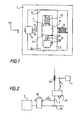
- FIG. 1 represents a conventional commercial translator with two degrees of freedom. In a similar way, by fixing three monodimensional modules in series, one would obtain a device with three degrees of freedom.
- the main limits of kinematic systems are given by the machining precision of the slides, the play, the friction, the wear.
- these devices remain ill-suited to certain applications requiring a typical precision of the tenth of a micron, such as for example the positioning or the assembly of components of single mode guided optics.
- a monolithic elastic system can advantageously be produced by the known method of EDM machining.
- a device monolithic complex of elastic guidance, piloted by piezoelectric actuators, is reported by RD Young, in the article entitled “Moving Stage Improves Accuracy of Microcircuit Measuring Technique", and published in Research & Development (April 1984) p. 1-14.
- Piezoelectric actuators although offering extremely high resolution, have a number of drawbacks, among which: the requirement for a control voltage, which can reach values greater than 1000 volts, their non-linear response and l existence of a significant hysteresis.
- the use of such actuators requires the presence of a displacement detector incorporated in a control loop which is associated with each actuator.
- Micrometric screw actuators offer the advantage of a large stroke but have the disadvantage of being relatively heavy and bulky.
- the placing in series of several positioning modules with a degree of freedom, in order to obtain displacements according to several coordinates, is no longer acceptable for systems with elastic guidance, sensitive to the effects of load and vibrations, if one wishes to pull take advantage of their properties and their high intrinsic precision.
- an object of the present invention is a micrositioning device which does not have the limitations of the systems described above.
- Another object of the invention is a micro-positioning device with several degrees of freedom allowing the assembly of single-mode guided optics components.
- Another object of the invention is a micro-positioning device using elastic type guide means.
- Another object of the invention is a micrositioning device with a compact and space-saving structure.
- Another object of the invention is a micrositioning device that can be produced by electro-erosion.
- a micro-positioning device with N degrees of freedom (2nd N ⁇ 6) comprising at least two rigid elements connected by guide means and constituting the first, a reference base and the second, a mobile platform , is characterized in that the guide means are distributed in N chains independent of each other, in that each chain comprises N elastic guide means connected in series between the reference base and the mobile and corresponding platform, each , at one of the N degrees of freedom and in that there are provided N actuators connected to said reference base and actuating the guide means connected to the reference base of the corresponding chains.
- FIG. 1 A known diagram of a positioning device with two degrees of freedom is shown in Figure 1. It consists of a base frame 1, on which can slide an intermediate platform 2 which serves as a base frame for the mobile platform 3.
- the support of the platform 2 is provided by the spring 13 and that of the mobile platform 3 is provided by the spring 23.
- the kinematic guides of the two translational movements are provided, respectively, by the support zones 15 and 16 for the platform 2 and by the support zones 25 and 26 for the mobile platform 3.
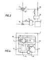
- the device of Figure 1 is schematically shown in Figure 2 so as to make more explicit the series connection of the two displacement modules. It thus appears clearly that on the one hand, the two kinematic chains, in the directions x and y, are dependent on each other and on the other hand, if the actuator 10 is secured to the platform fixed reference 1, the actuator 20 is integral with a movable part 2.
- the serial effect of the kinematic chains has the primary effect that the errors due to each chain are added to each other.
- the fact of fixing an actuator on a mobile part constitutes a disadvantage when compact structures and low masses in movement are sought.
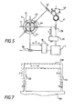
- FIG. 3 shows the explanatory diagram of a device with two perpendicular translational movements, in accordance with the principles of the invention.
- the device comprises a reference platform 1, two actuators 10 and 20 for transmitting the translation movements along the axes x and y respectively and a mobile platform 3.
- the two actuators are integral with the platform - reference form and the two kinematic chains are independent of each other.
- the first chain comprises the actuator 10, a first guide means 18 and a second guide means 27.
- the second chain comprises the actuator 20, a first guide means 28 and a second guide means 17.
- Each chain is located thus connecting the reference platform 1 on the one hand and the mobile platform 3 on the other.
- Such an assembly can be qualified as a parallel assembly as opposed to the series assembly in FIG. 2.
- the guide means 17 and 27 also constitute means for decoupling one chain from the other.
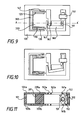
- the reference platform 1 has two to two perpendicular bearing surfaces (such as the surfaces 18 and 28) serving as sliding guides for two platforms. intermediate forms 19 and 29. These platforms are controlled by two actuators 10 and 20, integral with the reference platform 1, and themselves have support surfaces also two by two perpendicular (such as surfaces 17 and 27) and serving as sliding guides to the mobile platform 3.
- FIG. 5 shows another explanatory diagram of a device in accordance with the principles of the invention but offering three degrees of freedom corresponding to two translations and one rotation.
- the chain corresponding to the rotational movement comprises the actuator 40, integral with the reference platform 1, and the guide means 41, 42 and 44.
- FIG. 6 shows an exemplary embodiment of a device with three degrees of freedom corresponding to three translations in three perpendicular directions denoted x, y and z.
- the reference base 1 is in the form of a right-angled trihedron, each of the three faces of which has support zones (18, 28 and 58).
- the first kinematic chain comprises the actuator 10 and the guide means 18, 27 and 57 '.
- the second chain comprises the actuator 20 and the guide means 28, 57 and 17 '.
- the third chain comprises the actuator 50 and the guide means 58, 17 and 27 '.
- the mobile platform 3 is therefore controlled in translation in three directions by three independent chains and connected to the reference base 1.
- FIG. 7 shows the principle of elastic guidance in the case of a translational movement.
- the mobile platform 200 is attached to a reference base 100 by two thin and parallel elastic blades 110 and 120.
- the mobile platform is capable of displacement in the direction of the arrow, when it is subjected to a appropriate action, thanks to the bending of the elastic blades. It is possible to define two pivot axes per blade, ie the axes marked A, B, C and D for blades 110 and 120. Due to the rotational movements around the previously defined axes, the movement of the mobile platform 200 is not strictly straight.
- FIG. 8 shows a device for translation by elastic guidance in which the displacement errors due to rotation are compensated for.
- the device is in the form of a double parallelogram.
- the mobile platform 200 is attached, by two elastic blades 110 and 120, to an intermediate platform 300, which is attached to a reference base 100 by two elastic blades 130 and 140, parallel to the first two.
- Such a device is described for example in the aforementioned article by PH Sydenham.
- FIG. 9 shows an exemplary embodiment of the device incorporating control means.
- the control of the mobile platform 200 is ensured by an actuator 150, fixed to the reference base and a rigid transmission lever 160 which is connected to the actuator, the reference base and the mobile platform by three elastic blades 161, 162 and 163 respectively.
- This arrangement for controlling the mobile platform makes it possible to reduce the effect of a lack of precision at the level of the actuator (for example a micrometric screw) thanks to the reduction operated by the lever.
- the elastic blades 161 to 163 can be of unequal lengths but must have their centers aligned.
- An advantageous solution both from the point of view of manufacturing cost and from the point of view of performance, consists in producing these devices in monolithic form. All the elements of the chain are cut in the same plate, for example by EDM in an aluminum plate.
- Figure 11 shows a sectional view of an exemplary embodiment of a device with a degree of freedom in which, to increase the rigidity of the different parts in directions other than that of the desired movement, two plates identical to that of Figure 9 were arranged in parallel and joined by spacers.
- the section in the direction AA 'of FIG. 9, shows an upper plate and a lower plate joined by three spacers 101, 102 and 201.
- the two spacers 101 and 102 rigidly connect the two reference bases 100a and 100b, while the spacer 201 rigidly connects between them the mobile platforms 200a and 200b.
- FIG. 11 also shows the actuator which is constituted by a micrometric screw 151 acting on a sliding nut 152, which is connected to the blades 161a and 161b.
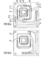
- FIG. 12 shows a preferred embodiment of two planar structures allowing two translational movements to be obtained in two perpendicular directions.
- the two structures of Figure 12.a and Figure 12.b are identical and intended to be arranged one on the other so as to allow movements in the directions x and y.
- the kinematic chain constituted by the transmission lever 160, the thin blades 162 and 163, the intermediate platform 300 and the elastic blades 110 to 140 can be recognized.
- Means for decoupling between the movements in the directions x and They are also provided in the form of a second configuration in double parallelogram.
- This second configuration comprising a second intermediate platform 400 and the elastic blades 170, 171, 180 and 181, is perpendicular to the first and makes it possible to decouple the two kinematic chains.
- the mobile platform 200 is provided with a central hole so as to allow the mounting, for example, of optical components.
- Figure 12.b also shows the location of spacers 500 connecting together the reference bases of the four planar structures forming, as indicated previously, a compact two-stage assembly and the location of the central spacer connecting together the mobile platforms of the same four structures.
Landscapes
- Engineering & Computer Science (AREA)
- Mechanical Engineering (AREA)
- Physics & Mathematics (AREA)
- General Physics & Mathematics (AREA)
- Machine Tool Units (AREA)
- Details Of Measuring And Other Instruments (AREA)
- Control Of Position Or Direction (AREA)
- Mounting And Adjusting Of Optical Elements (AREA)
- Prostheses (AREA)
- Superconductors And Manufacturing Methods Therefor (AREA)
- Electrotherapy Devices (AREA)
- Motorcycle And Bicycle Frame (AREA)
Priority Applications (1)
| Application Number | Priority Date | Filing Date | Title |
|---|---|---|---|
| AT86810382T ATE63393T1 (de) | 1985-08-30 | 1986-08-27 | Vorrichtung fuer die mikropositionierung. |
Applications Claiming Priority (2)
| Application Number | Priority Date | Filing Date | Title |
|---|---|---|---|
| FR8512944 | 1985-08-30 | ||
| FR8512944A FR2586853B1 (fr) | 1985-08-30 | 1985-08-30 | Dispositif de micropositionnement |
Publications (2)
| Publication Number | Publication Date |
|---|---|
| EP0218546A1 true EP0218546A1 (de) | 1987-04-15 |
| EP0218546B1 EP0218546B1 (de) | 1991-05-08 |
Family
ID=9322504
Family Applications (1)
| Application Number | Title | Priority Date | Filing Date |
|---|---|---|---|
| EP86810382A Expired - Lifetime EP0218546B1 (de) | 1985-08-30 | 1986-08-27 | Vorrichtung für die Mikropositionierung |
Country Status (7)
| Country | Link |
|---|---|
| US (1) | US4805543A (de) |
| EP (1) | EP0218546B1 (de) |
| JP (1) | JPH0760191B2 (de) |
| AT (1) | ATE63393T1 (de) |
| CA (1) | CA1285759C (de) |
| DE (1) | DE3679141D1 (de) |
| FR (1) | FR2586853B1 (de) |
Cited By (5)
| Publication number | Priority date | Publication date | Assignee | Title |
|---|---|---|---|---|
| DE3926949A1 (de) * | 1988-08-17 | 1990-02-22 | Canon Kk | Buehnenmechanismus fuer ein wafer-belichtungsgeraet |
| EP0335126A3 (de) * | 1988-03-10 | 1991-10-16 | Wendel Schmidt | Mehrachsige Juwelierswerkstückstütze und Positionierungsvorrichtung |
| WO2001021296A1 (de) * | 1999-09-23 | 2001-03-29 | Siat Gmbh | Mehrdimensionaler antrieb für arbeitsmaschinen |
| CN104238273A (zh) * | 2013-06-19 | 2014-12-24 | 上海微电子装备有限公司 | 一种工件台安全防护装置 |
| US8984982B2 (en) | 2006-10-31 | 2015-03-24 | Force Dimension S.A.R.L. | Parallel kinematic structure |
Families Citing this family (17)
| Publication number | Priority date | Publication date | Assignee | Title |
|---|---|---|---|---|
| JPH0259494U (de) * | 1988-10-21 | 1990-05-01 | ||
| DE3905952A1 (de) * | 1989-02-25 | 1990-08-30 | Kugelfischer G Schaefer & Co | Mehrkoordinatenmesstaster |
| US5943914A (en) * | 1997-03-27 | 1999-08-31 | Sandia Corporation | Master-slave micromanipulator apparatus |
| US6346710B1 (en) | 1998-08-31 | 2002-02-12 | Olympus Optical Co., Ltd. | Stage apparatus including displacement amplifying mechanism |
| US6445514B1 (en) * | 2000-10-12 | 2002-09-03 | Honeywell International Inc. | Micro-positioning optical element |
| GB0217734D0 (en) * | 2002-07-31 | 2002-09-11 | Pbt Ip Ltd | Reversing linkage |
| US7068891B1 (en) | 2002-03-12 | 2006-06-27 | Palomar Technologies, Inc. | System and method for positioning optical fibers |
| US7107693B2 (en) * | 2005-01-14 | 2006-09-19 | Illinois Institute Of Technology | Apparatus and method for precise angular positioning |
| JP5031459B2 (ja) * | 2007-06-27 | 2012-09-19 | 株式会社アルバック | 粗微移動装置及びそれを備えた液体供給装置 |
| CN100486413C (zh) * | 2007-10-26 | 2009-05-06 | 华南理工大学 | 基于柔顺机构的全自动无铅锡膏印刷机定位平台 |
| WO2010011953A1 (en) * | 2008-07-25 | 2010-01-28 | Sloan Kettering Institute For Cancer Research | Rapid confocal microscopy to support surgical procedures |
| CN102152131B (zh) * | 2011-02-28 | 2012-06-13 | 西安理工大学 | 滚珠丝杠副压电致动器串联宏微驱动及导轨装置 |
| CN102623070A (zh) * | 2012-03-30 | 2012-08-01 | 中国科学院长春光学精密机械与物理研究所 | 一种二自由度微位移精密定位装置 |
| US9312790B2 (en) * | 2013-09-13 | 2016-04-12 | Physik Instrumente (Pi) Gmbh & Co. Kg | Compact versatile stick-slip piezoelectric motor |
| CN104742099B (zh) * | 2015-04-09 | 2016-05-18 | 南京航空航天大学 | 一种自行式平面三自由度压电驱动平台 |
| CN105551836B (zh) * | 2016-01-18 | 2018-04-17 | 北京邮电大学 | 一种二维微动平台装置 |
| CN107833594B (zh) * | 2017-09-13 | 2020-02-21 | 南京航空航天大学 | 一种用于高精度定位和测量的二维三自由度微动平台结构 |
Citations (4)
| Publication number | Priority date | Publication date | Assignee | Title |
|---|---|---|---|---|
| FR2220807A1 (de) * | 1973-03-09 | 1974-10-04 | Perkin Elmer Corp | |
| EP0017144A1 (de) * | 1979-04-06 | 1980-10-15 | Hitachi, Ltd. | Vorrichtung zum genauen Versetzen eines Tisches |
| EP0134268A1 (de) * | 1983-08-09 | 1985-03-20 | Siemens Aktiengesellschaft | Justier- oder Positioniertisch und Verfahren zu dessen Herstellung |
| EP0149017A2 (de) * | 1983-12-30 | 1985-07-24 | International Business Machines Corporation | Piezoelektrische X-Y Verstellung |
Family Cites Families (12)
| Publication number | Priority date | Publication date | Assignee | Title |
|---|---|---|---|---|
| GB624331A (en) * | 1947-07-03 | 1949-06-02 | William Donald Douglas | Improvements in or relating to lever systems, apparatus incorporating lever systems and a method of fabricating lever systems |
| US3124018A (en) * | 1961-07-07 | 1964-03-10 | gough | |
| BE682178A (de) * | 1966-06-07 | 1966-11-14 | ||
| DE2220807A1 (de) * | 1971-04-30 | 1972-11-16 | Texas Instruments Inc | Verfahren und Vorrichtung zum Abscheiden von polykristallinen Duennfilmen aus Silicium und Siliciumdioxid auf Halbleitersubstraten |
| AT337572B (de) * | 1975-07-28 | 1977-07-11 | Philips Nv | Elektromotorisch angetriebenes gerat |
| US4012111A (en) * | 1975-08-25 | 1977-03-15 | Honeywell Inc. | Microscope object slide positioning system |
| JPS6041953B2 (ja) * | 1979-03-16 | 1985-09-19 | 松下電工株式会社 | 電気かみなりの往復駆動装置 |
| JPS5640852A (en) * | 1979-09-12 | 1981-04-17 | Canon Inc | Electrophotographic device |
| US4595257A (en) * | 1983-05-18 | 1986-06-17 | Itp, Inc. | Support mechanism utilizing flexual pivots |
| DE3346656C1 (de) * | 1983-12-23 | 1988-12-22 | Braun Ag, 6000 Frankfurt | Vorrichtung zur Umwandlung der Drehbewegung eines Exzenters in eine hin- und hergehende Bewegung |
| US4559717A (en) * | 1984-02-21 | 1985-12-24 | The United States Of America As Represented By The Secretary Of Commerce | Flexure hinge |
| GB2185323B (en) * | 1984-10-12 | 1988-01-06 | Vickers Plc | Microscope having an improved stage |
-
1985
- 1985-08-30 FR FR8512944A patent/FR2586853B1/fr not_active Expired
-
1986
- 1986-08-27 DE DE8686810382T patent/DE3679141D1/de not_active Expired - Lifetime
- 1986-08-27 US US06/900,693 patent/US4805543A/en not_active Expired - Lifetime
- 1986-08-27 AT AT86810382T patent/ATE63393T1/de active
- 1986-08-27 EP EP86810382A patent/EP0218546B1/de not_active Expired - Lifetime
- 1986-08-29 JP JP61201889A patent/JPH0760191B2/ja not_active Expired - Lifetime
- 1986-08-29 CA CA000517241A patent/CA1285759C/fr not_active Expired - Lifetime
Patent Citations (4)
| Publication number | Priority date | Publication date | Assignee | Title |
|---|---|---|---|---|
| FR2220807A1 (de) * | 1973-03-09 | 1974-10-04 | Perkin Elmer Corp | |
| EP0017144A1 (de) * | 1979-04-06 | 1980-10-15 | Hitachi, Ltd. | Vorrichtung zum genauen Versetzen eines Tisches |
| EP0134268A1 (de) * | 1983-08-09 | 1985-03-20 | Siemens Aktiengesellschaft | Justier- oder Positioniertisch und Verfahren zu dessen Herstellung |
| EP0149017A2 (de) * | 1983-12-30 | 1985-07-24 | International Business Machines Corporation | Piezoelektrische X-Y Verstellung |
Cited By (6)
| Publication number | Priority date | Publication date | Assignee | Title |
|---|---|---|---|---|
| EP0335126A3 (de) * | 1988-03-10 | 1991-10-16 | Wendel Schmidt | Mehrachsige Juwelierswerkstückstütze und Positionierungsvorrichtung |
| DE3926949A1 (de) * | 1988-08-17 | 1990-02-22 | Canon Kk | Buehnenmechanismus fuer ein wafer-belichtungsgeraet |
| WO2001021296A1 (de) * | 1999-09-23 | 2001-03-29 | Siat Gmbh | Mehrdimensionaler antrieb für arbeitsmaschinen |
| US8984982B2 (en) | 2006-10-31 | 2015-03-24 | Force Dimension S.A.R.L. | Parallel kinematic structure |
| CN104238273A (zh) * | 2013-06-19 | 2014-12-24 | 上海微电子装备有限公司 | 一种工件台安全防护装置 |
| CN104238273B (zh) * | 2013-06-19 | 2016-09-28 | 上海微电子装备有限公司 | 一种工件台安全防护装置 |
Also Published As
| Publication number | Publication date |
|---|---|
| DE3679141D1 (de) | 1991-06-13 |
| JPH0760191B2 (ja) | 1995-06-28 |
| FR2586853A1 (fr) | 1987-03-06 |
| CA1285759C (fr) | 1991-07-09 |
| US4805543A (en) | 1989-02-21 |
| EP0218546B1 (de) | 1991-05-08 |
| ATE63393T1 (de) | 1991-05-15 |
| FR2586853B1 (fr) | 1988-07-29 |
| JPS6255590A (ja) | 1987-03-11 |
Similar Documents
| Publication | Publication Date | Title |
|---|---|---|
| EP0218546B1 (de) | Vorrichtung für die Mikropositionierung | |
| EP0840023B1 (de) | Flexibles planares Gelenk mit einzelnen, monolithischen Modulen | |
| EP0222652B1 (de) | Kraft- und Torsionsmessvorrichtung und ihre Anwendung an einer Fühler- oder Greifeinrichtung | |
| WO1999038044A1 (fr) | Ensemble de montage et de correction de position d'un organe, tel qu'un miroir, d'un telescope spatial | |
| EP0269925A1 (de) | Vorrichtung für die Verschiebung eines Faserendes in zwei orthogonalen Richtungen | |
| FR2721115A1 (fr) | Dispositif de commande d'une lentille d'objectif pour une tête optique. | |
| EP1960307A1 (de) | Mikroelektromechanisches system mit einem verformbaren teil und einem belastungssensor | |
| EP0245199A1 (de) | Kapazitiver Positionsdetektor | |
| FR2562254A1 (fr) | Accelerometre | |
| WO2002075365A2 (fr) | Dispositif de fixation et de reglage d'un organe a supporter | |
| EP0742459B1 (de) | Optomechanischer Mikro-Strahlablenker unter Verwendung der Verschiebung von Mikrolinsen | |
| EP1402992A1 (de) | Vorrichtung mit höher Präzision zum Vorgeben oder zum Messen einer Position oder Kraft | |
| EP0413639B1 (de) | Zusammenbau von Teilen mit einem gegenseitigen Winkel und Verfahren zur Herstellung | |
| EP2598929B1 (de) | Passives mechanisches athermalisationsvorrichtung und zugehöriges optisches system | |
| EP2570842A1 (de) | Spiegel mit mechanischen Mitteln zum generieren von primairen geometrischen Aberrationen | |
| FR2784745A1 (fr) | Detecteur de position a cellule de detection micro-usinee | |
| EP0403354B1 (de) | Führungsvorrichtung für ein mobiles Element parallel zu einer Achse und Instrument mit einer derartigen Führung | |
| EP3203299A1 (de) | Verformbarer spiegel | |
| EP0331581A1 (de) | Piezoelektrischer Spiegel für Laserkreisel | |
| EP3670932B1 (de) | Montagevorrichtung des verriegelungstyps mit einem mechanismus mit bidirektionalen keilen | |
| EP1160602A1 (de) | Ausrichtung eines Flipchiplasers in einer schrägen Position auf einer Montageebene mit Ausrichtpfosten | |
| WO2002086584A1 (fr) | Commutateur optique multivoie | |
| EP4078219A1 (de) | Optoelektronisches bauelement, das auf einem einzigen substrat einen optischen wandler aus einem halbleitermaterial iii-v und ein optisch abtastendes mikroelektromechanisches system umfasst | |
| EP0159227B1 (de) | Optischer Wähler | |
| EP3913418A1 (de) | Optisches system mit variabler brennweite und optische anordnung mit einem solchen system |
Legal Events
| Date | Code | Title | Description |
|---|---|---|---|
| PUAI | Public reference made under article 153(3) epc to a published international application that has entered the european phase |
Free format text: ORIGINAL CODE: 0009012 |
|
| AK | Designated contracting states |
Kind code of ref document: A1 Designated state(s): AT BE CH DE GB IT LI LU NL SE |
|
| 17P | Request for examination filed |
Effective date: 19870725 |
|
| 17Q | First examination report despatched |
Effective date: 19891012 |
|
| GRAA | (expected) grant |
Free format text: ORIGINAL CODE: 0009210 |
|
| AK | Designated contracting states |
Kind code of ref document: B1 Designated state(s): AT BE CH DE GB IT LI LU NL SE |
|
| PG25 | Lapsed in a contracting state [announced via postgrant information from national office to epo] |
Ref country code: SE Effective date: 19910508 Ref country code: NL Effective date: 19910508 Ref country code: AT Effective date: 19910508 |
|
| REF | Corresponds to: |
Ref document number: 63393 Country of ref document: AT Date of ref document: 19910515 Kind code of ref document: T |
|
| REF | Corresponds to: |
Ref document number: 3679141 Country of ref document: DE Date of ref document: 19910613 |
|
| GBT | Gb: translation of ep patent filed (gb section 77(6)(a)/1977) | ||
| ITF | It: translation for a ep patent filed | ||
| PG25 | Lapsed in a contracting state [announced via postgrant information from national office to epo] |
Ref country code: LU Free format text: LAPSE BECAUSE OF NON-PAYMENT OF DUE FEES Effective date: 19910831 Ref country code: BE Effective date: 19910831 |
|
| K2C3 | Correction of patent specification (complete document) published |
Effective date: 19910508 |
|
| NLV1 | Nl: lapsed or annulled due to failure to fulfill the requirements of art. 29p and 29m of the patents act | ||
| BERE | Be: lapsed |
Owner name: S.A. CENTRE SUISSE D'ELECTRONIQUE ET DE MICROTECH Effective date: 19910831 |
|
| PLBE | No opposition filed within time limit |
Free format text: ORIGINAL CODE: 0009261 |
|
| STAA | Information on the status of an ep patent application or granted ep patent |
Free format text: STATUS: NO OPPOSITION FILED WITHIN TIME LIMIT |
|
| 26N | No opposition filed | ||
| PGFP | Annual fee paid to national office [announced via postgrant information from national office to epo] |
Ref country code: GB Payment date: 20010822 Year of fee payment: 16 |
|
| PGFP | Annual fee paid to national office [announced via postgrant information from national office to epo] |
Ref country code: CH Payment date: 20010907 Year of fee payment: 16 |
|
| PGFP | Annual fee paid to national office [announced via postgrant information from national office to epo] |
Ref country code: DE Payment date: 20011017 Year of fee payment: 16 |
|
| REG | Reference to a national code |
Ref country code: GB Ref legal event code: IF02 |
|
| PG25 | Lapsed in a contracting state [announced via postgrant information from national office to epo] |
Ref country code: GB Free format text: LAPSE BECAUSE OF NON-PAYMENT OF DUE FEES Effective date: 20020827 |
|
| PG25 | Lapsed in a contracting state [announced via postgrant information from national office to epo] |
Ref country code: LI Free format text: LAPSE BECAUSE OF NON-PAYMENT OF DUE FEES Effective date: 20020831 Ref country code: CH Free format text: LAPSE BECAUSE OF NON-PAYMENT OF DUE FEES Effective date: 20020831 |
|
| PG25 | Lapsed in a contracting state [announced via postgrant information from national office to epo] |
Ref country code: DE Free format text: LAPSE BECAUSE OF NON-PAYMENT OF DUE FEES Effective date: 20030301 |
|
| REG | Reference to a national code |
Ref country code: CH Ref legal event code: PL |
|
| GBPC | Gb: european patent ceased through non-payment of renewal fee |
Effective date: 20020827 |
|
| PG25 | Lapsed in a contracting state [announced via postgrant information from national office to epo] |
Ref country code: IT Free format text: LAPSE BECAUSE OF NON-PAYMENT OF DUE FEES Effective date: 20050827 |