EP1402992A1 - Vorrichtung mit höher Präzision zum Vorgeben oder zum Messen einer Position oder Kraft - Google Patents
Vorrichtung mit höher Präzision zum Vorgeben oder zum Messen einer Position oder Kraft Download PDFInfo
- Publication number
- EP1402992A1 EP1402992A1 EP02079069A EP02079069A EP1402992A1 EP 1402992 A1 EP1402992 A1 EP 1402992A1 EP 02079069 A EP02079069 A EP 02079069A EP 02079069 A EP02079069 A EP 02079069A EP 1402992 A1 EP1402992 A1 EP 1402992A1
- Authority
- EP
- European Patent Office
- Prior art keywords
- articulated
- translation
- parallel
- platform
- kinematic
- Prior art date
- Legal status (The legal status is an assumption and is not a legal conclusion. Google has not performed a legal analysis and makes no representation as to the accuracy of the status listed.)
- Withdrawn
Links
- 238000013519 translation Methods 0.000 claims abstract description 104
- 230000005540 biological transmission Effects 0.000 claims abstract description 44
- 238000006073 displacement reaction Methods 0.000 claims abstract description 18
- 210000001503 joint Anatomy 0.000 claims description 42
- 238000005259 measurement Methods 0.000 claims description 10
- 230000014616 translation Effects 0.000 description 83
- 230000003287 optical effect Effects 0.000 description 11
- 238000010276 construction Methods 0.000 description 7
- 230000007246 mechanism Effects 0.000 description 6
- 230000006835 compression Effects 0.000 description 5
- 238000007906 compression Methods 0.000 description 5
- 238000000034 method Methods 0.000 description 5
- 238000005452 bending Methods 0.000 description 4
- 230000008901 benefit Effects 0.000 description 4
- 230000000694 effects Effects 0.000 description 4
- 238000004519 manufacturing process Methods 0.000 description 4
- 229910052751 metal Inorganic materials 0.000 description 4
- 239000002184 metal Substances 0.000 description 4
- 238000010586 diagram Methods 0.000 description 2
- 230000005484 gravity Effects 0.000 description 2
- 238000000338 in vitro Methods 0.000 description 2
- 238000003754 machining Methods 0.000 description 2
- 238000010008 shearing Methods 0.000 description 2
- RTAQQCXQSZGOHL-UHFFFAOYSA-N Titanium Chemical compound [Ti] RTAQQCXQSZGOHL-UHFFFAOYSA-N 0.000 description 1
- 230000008859 change Effects 0.000 description 1
- 238000001816 cooling Methods 0.000 description 1
- 239000000428 dust Substances 0.000 description 1
- 230000004720 fertilization Effects 0.000 description 1
- 230000003993 interaction Effects 0.000 description 1
- 239000007788 liquid Substances 0.000 description 1
- 238000005461 lubrication Methods 0.000 description 1
- 238000012423 maintenance Methods 0.000 description 1
- 238000002406 microsurgery Methods 0.000 description 1
- 239000013307 optical fiber Substances 0.000 description 1
- 230000005693 optoelectronics Effects 0.000 description 1
- 239000002245 particle Substances 0.000 description 1
- 230000008569 process Effects 0.000 description 1
- 230000001681 protective effect Effects 0.000 description 1
- 230000035939 shock Effects 0.000 description 1
- 238000001356 surgical procedure Methods 0.000 description 1
- 239000010936 titanium Substances 0.000 description 1
- 229910052719 titanium Inorganic materials 0.000 description 1
Images


Classifications
-
- F—MECHANICAL ENGINEERING; LIGHTING; HEATING; WEAPONS; BLASTING
- F16—ENGINEERING ELEMENTS AND UNITS; GENERAL MEASURES FOR PRODUCING AND MAINTAINING EFFECTIVE FUNCTIONING OF MACHINES OR INSTALLATIONS; THERMAL INSULATION IN GENERAL
- F16C—SHAFTS; FLEXIBLE SHAFTS; ELEMENTS OR CRANKSHAFT MECHANISMS; ROTARY BODIES OTHER THAN GEARING ELEMENTS; BEARINGS
- F16C11/00—Pivots; Pivotal connections
- F16C11/04—Pivotal connections
- F16C11/12—Pivotal connections incorporating flexible connections, e.g. leaf springs
-
- B—PERFORMING OPERATIONS; TRANSPORTING
- B23—MACHINE TOOLS; METAL-WORKING NOT OTHERWISE PROVIDED FOR
- B23Q—DETAILS, COMPONENTS, OR ACCESSORIES FOR MACHINE TOOLS, e.g. ARRANGEMENTS FOR COPYING OR CONTROLLING; MACHINE TOOLS IN GENERAL CHARACTERISED BY THE CONSTRUCTION OF PARTICULAR DETAILS OR COMPONENTS; COMBINATIONS OR ASSOCIATIONS OF METAL-WORKING MACHINES, NOT DIRECTED TO A PARTICULAR RESULT
- B23Q1/00—Members which are comprised in the general build-up of a form of machine, particularly relatively large fixed members
- B23Q1/25—Movable or adjustable work or tool supports
- B23Q1/26—Movable or adjustable work or tool supports characterised by constructional features relating to the co-operation of relatively movable members; Means for preventing relative movement of such members
- B23Q1/34—Relative movement obtained by use of deformable elements, e.g. piezoelectric, magnetostrictive, elastic or thermally-dilatable elements
- B23Q1/36—Springs
-
- F—MECHANICAL ENGINEERING; LIGHTING; HEATING; WEAPONS; BLASTING
- F16—ENGINEERING ELEMENTS AND UNITS; GENERAL MEASURES FOR PRODUCING AND MAINTAINING EFFECTIVE FUNCTIONING OF MACHINES OR INSTALLATIONS; THERMAL INSULATION IN GENERAL
- F16H—GEARING
- F16H21/00—Gearings comprising primarily only links or levers, with or without slides
- F16H21/04—Guiding mechanisms, e.g. for straight-line guidance
-
- F—MECHANICAL ENGINEERING; LIGHTING; HEATING; WEAPONS; BLASTING
- F16—ENGINEERING ELEMENTS AND UNITS; GENERAL MEASURES FOR PRODUCING AND MAINTAINING EFFECTIVE FUNCTIONING OF MACHINES OR INSTALLATIONS; THERMAL INSULATION IN GENERAL
- F16C—SHAFTS; FLEXIBLE SHAFTS; ELEMENTS OR CRANKSHAFT MECHANISMS; ROTARY BODIES OTHER THAN GEARING ELEMENTS; BEARINGS
- F16C2322/00—Apparatus used in shaping articles
- F16C2322/39—General buildup of machine tools, e.g. spindles, slides, actuators
Definitions
- the present invention relates to apparatuses for imposing or measuring a position or a force with at least four degrees of freedom, comprising a fixed base, a mobile platform, articulated links connecting in parallel the mobile platform to the base, and measuring means, said articulated links comprising at least four articulated kinematic units each of which is mounted on the base and connected to a connection point of the platform to accompany a translational movement of this point in a direction substantially parallel to the '' one of the main axes (X, Y, Z) of a space mark, at least one pair of said kinematic units being connected to two of said connection points distant from each other and arranged to accompany them in translation in the same direction and thus accompany a rotation of the platform when the amplitudes of translation of these two points are unequal.
- Such a device can be used for example to manipulate objects with great precision and with a number of degrees of freedom of up to six, if each of the articulated kinematic units is equipped with a linear actuator and a displacement sensor for allow the amplitude of its translation to be adjusted with the desired precision.
- a parallel manipulator with six degrees of freedom belonging to the category known under the name of "Stewart platform”.
- Each pair of articulated kinematic units oriented along the same axis accompanies a translation of the mobile platform and the object attached to it when the two units perform translations of the same amplitude, and a rotation of the platform when these units perform unequal translations.
- Manipulators of the parallel type are characterized by several kinematic connections arranged in parallel to connect the fixed base to the mobile platform.
- one or more of the kinematic connections can be formed from two articulated devices coupled in series in order to ensure two degrees of freedom for this connection.
- the movement transmission device described in this application can be used in a positioning or measuring device and can provide up to three degrees of freedom in translation of the platform thanks to three parallel kinematic units each comprising two parallelograms in series.
- Such kinematic connections have the drawbacks inherent in series arrangements, in particular the fact that the first parallelogram articulated from the base must support and move the entire mass of the second and that the amplitude of the movement allowed by such a series connection is necessarily restricted.
- an apparatus according to the invention is of an entirely parallel type, so that the drive or the measurement of position or force in each articulated connection between the base and the platform is carried out with a single degree of freedom.
- Patent application EP 0 937 961 describes such a positioning device with six degrees of freedom of the fully parallel type.
- the mobile platform is connected to three pairs of articulated arms, each pair of arms being parallel to one of the three perpendicular axes of a Cartesian orthogonal coordinate system.
- the two arms of each pair are fixed on the other hand to a plate mounted on a ball joint and associated with two micrometric screws making it possible to pivot this plate along two mutually perpendicular axes of rotation, to impose a translation on the platform. and / or a rotation.
- Each arm has two joints formed by a longitudinal wire and thus allowing a bending along two axes, and even a twist if necessary.
- the present invention aims to create a positioning or measuring device with four, five or six degrees of freedom having a simple and robust construction, allowing a large range of movement of the mobile platform and a very high accuracy of determination or measuring positions, displacements or forces according to each degree of freedom.
- An additional goal is to provide the device with a particularly rigid frame while being fairly simple to manufacture.
- Another additional aim is to arrange the device in the form of a combination of similar modules, in order to simplify its manufacture and maintenance and reduce the corresponding costs.
- Yet another additional object consists in arranging the apparatus so that the object mounted on the platform is easily accessible at the periphery of the apparatus, in particular so as to be able to be positioned relative to another object external to the apparatus .
- each of the articulated kinematic units comprises an elastically deformable parallelogram in its own plane, an articulated transmission device connecting the parallelogram to the platform, and a linear displacement sensor providing an output signal to the measuring means, the parallelogram comprising a support element linked to the base, a translation element linked to the transmission device and two parallel arms linked to the translation element and to the 'support element by joints without play, in particular elastic joints.
- each kinematic unit comprises an articulated mechanism without play, the parallelogram of which can have a stroke practically equal to that of the platform in the direction of translation concerned and be directly associated with the displacement sensor, which ensures very high accuracy of order or from measurement of positions and displacements, as well as high dynamics when this unit is provided with an actuator or a force measuring device.
- the mechanism allows a high speed of movement of the platform and does not present any mechanical hysteresis.
- the articulated mechanism can be configured entirely in a planar form, therefore compact and relatively easy to manufacture.
- the parallelogram configuration allows it to be arranged around certain elements such as an electromagnetic transducer and / or the displacement sensor, so that the parallelogram can be of a size large enough to allow a high linear stroke with limited angular strokes. joints. This also reduces the second order displacements, perpendicular to the direction of translation, which are caused by variations in the height of the parallelogram.
- the articulated mechanism is not only without play but also without friction and without wear. It therefore does not need lubrication and is not sensitive to the presence of dust, liquids or other dirt, which allows its use in a dirty environment. conversely, since the mechanism does not emit particles or other contaminating elements, it can advantageously be used in a clean room or a similar environment.
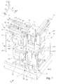
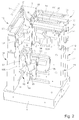
- the apparatus shown in Figures 1 to 8 has a fixed base 1 and a mobile platform 2 for supporting an object 3 (Figure 2), for example the end of an optical fiber that is position with great precision.
- the platform 2 is connected to the base 1 by six articulated links arranged in parallel, formed by six articulated kinematic units 11, 12, 13, 14, 15 and 16 each having a direction of translation parallel to one of the three axes X, Y and Z of a Cartesian orthogonal coordinate system.
- the three kinematic units 12, 14 and 16 have a direction of translation parallel to the axis Y, which is preferably vertical in the present case, the two kinematic units 11 and 13 have a direction of translation parallel to the X axis, while the sixth kinematic unit 15 has a direction of translation parallel to the Z axis.
- Y which is preferably vertical in the present case
- the two kinematic units 11 and 13 have a direction of translation parallel to the X axis
- the sixth kinematic unit 15 has a direction of translation parallel to the Z axis.
- the six aforementioned kinematic units are grouped two by two in three planar articulated structures 17, 18 and 19 which can advantageously constitute constructive modules, since they all have the same geometrical configuration and an identical construction, at least as regards concerned their main elements.
- these three structures extend in vertical planes, so that they can have a great rigidity with respect to the effects of gravity.
- the two articulated structures 17 and 18 are juxtaposed parallel and extend in planes parallel to that defined by the axes X and Y.
- the third articulated structure 19 is perpendicular to the other two and extends in a plane parallel to the axes Y and Z.
- FIGS. 8 and 9 respectively show the shape and the kinematic configuration of the planar articulated structure 17, which comprises the kinematic units 11 and 12.
- This structure is said to be planar because the longitudinal axes of its articulated elements are in principle in the same plane, at least in a starting position, but we will see later that some of them may undergo slight lateral deviations from this plane depending on the movements imposed on the platform 2.
- the articulated structure 17 comprises a frame 21 rigidly fixed to the base 1 and preferably formed by a thick plate which is cut so as to have several arms 22, 23 and 24 leaving free spaces 25 and 26 between them.
- the kinematic unit 11 comprises a translation element 30 and two identical and parallel arms 31 and 32, one end of which is connected to the frame 21 by an elastic joint 33 and the other end is connected to the translation element by an elastic joint 34.
- the four joints 33 and 34 are of the type with a single degree of freedom, which is represented by a white circle in FIG. 9. The axis of rotation of these joints is perpendicular to the plane of the drawing, therefore to the general plane of the structure 17.
- the elements 30 to 32 form with the frame 21 an elastically deformable parallelogram which allows the translation element 30 a translation movement Tx parallel to the axis X.
- the element 30 also undergoes vertical displacements, but these are second order and remain minimal as long as the arms 31 and 32 are close to the vertical.
- the translational element 30 is linked to the platform 2 by means of an articulated transmission arm 35 which is substantially horizontal and comprises an articulation 36 near its connection with the translational element 30 and an articulation 37 to proximity of its connection with the mobile platform 2.
- the articulation 36 is at two degrees of freedom, in other words of the cardan type, to allow the transmission arm 35 to follow the movements of the platform 2 in the directions Y and Z without transmitting any significant effort to the translation element 30 in these two directions.
- This type of joint is represented by a cross in a circle in FIG. 9.
- the joint 37 is of a type with three degrees of freedom, in other words with ball joint, represented by a black disc in FIG. 9, so that platform rotations 2 along the three axes X, Y and Z are not transmitted to the transmission arm 35.
- the two articulations 36 and 37 are rigid and free of play in the axial direction X of the transmission arm 35, so that the arm 35 rigorously transmits any Tx translation from element 30 to mobile platform 2 and vice versa.
- the frame 21 has a projecting stop 38 which extends in a gap between two lugs 39 (or two similar shoulders) of the translation element 30, so as to limit the maximum translation of the latter in both directions from the middle position shown.
- the width of this interval depends mainly on the length of the arms 31 and 32 and it is typically chosen so as to limit the inclination of these arms to around 5 degrees, which still allows a translation amplitude of several millimeters.
- the relatively large spacing of the arms 31 and 32 ensures good rigidity of the parallelogram.
- the second articulated kinematic unit 12 of the structure 17 is produced according to the same principles and comprises a translation element 40 arranged vertically which forms, with the frame 21 and two parallel articulated arms 41 and 42 provided with articulations 43 and 44, a parallelogram deformable allowing it to perform a translational movement Ty in the direction of the Y axis, that is to say in the vertical direction.
- the translation element 40 is connected to the platform 2 by a transmission arm 45 provided with articulations 46 and 47 near these ends.
- the joints 43, 44, 46 and 47 are identical to the joints 33, 34, 36 and 37 described above.
- the amplitude of the translation Ty of the translation element 40 is limited by a stop 48 secured to the frame 21 and located between two lugs 49 of the element 40.
- the two transmission arms 35 and 45 terminate in a common block 50 which is detachably fixed to the platform 2.
- translation elements 30 and 40 have respective plates 51 and 52 which extend in the free spaces 25 and 26 to allow these elements to be connected to actuators and respective sensors housed in these spaces, as is will see further.
- the articulated structure 17 described above can advantageously be produced in one piece from a metal plate, thanks to machining by electro-erosion.
- the preferred metal is titanium.
- the use of the EDM technique allows precise and rapid manufacturing of such a part at an acceptable cost.
- the plate used to produce it does not need to be very thick to have sufficient rigidity with respect to with regard to the effects of gravity, since it is easy to give sufficient dimensions in the plane of the plate to the parts concerned of this structure, in particular to its frame 21.
- Figures 10 to 12 show three known forms of elastic joints with a single degree of freedom, which can be used to form the joints 33, 34, 43 and 44 described above.
- These three embodiments comprise a thinned part forming a flexible blade 55 which allows a relative rotation of the adjacent parts with respect to a transverse axis located in its plane, almost without opposing resistance, but by allowing only relatively weak rotations around the two other perpendicular axes.
- this thinned part is sufficiently rigid in compression to transmit longitudinal movements without risk of buckling. Electro-erosion techniques allow these joints to be produced with great precision.
- the succession of two joints of this type constitutes a joint of the universal joint type and can be used to form the joints 36 and 46 described above.
- a joint of the type shown in Figure 13 having a thinned rod-shaped portion 56 which is laterally flexible in any direction, but sufficiently rigid in compression.
- FIG. 14 represents an advantageous embodiment of a torsional articulation, of which FIG. 15 shows a section at mid-height.
- this articulation is formed by thinning of a metal bar, in order to allow relative movement of the adjacent parts 60 and 61 of this bar.
- it is a pure torsional movement, namely a rotation around the longitudinal axis 62 of the bar, without rotation around the two axes perpendicular thereto and without transverse displacement between the two parts. 60 and 61.
- the thinned part is formed by two pairs of flexible blades 63 and 64 parallel to the axis 62, the two blades 63 being located in the same plane A and the other two blades 64 being located in the same plane B which forms with the plane A an angle C large enough for the blades 64 to be relatively distant from the plane A, and the blades 63 relatively distant from the plane B.
- This arrangement prevents any movement of bending or shearing between the parts 61 and 62 of the bar , thanks to the rigidity of the blades 63 and 64 in their own plane.
- the joint shown in FIGS. 14 and 15 has the advantage of being much more rigid in compression and of preventing any transverse displacement by shearing.
- it since it is empty in its central region, it can advantageously be manufactured by a wire EDM technique, which is less expensive than EDM.
- the angle C shown in FIG. 15 has a value less than 90 ° in order to facilitate the process of wire EDM with current machines.
- a torsion articulation produced according to the principles used in the articulation of FIGS. 14 and 15 must comprise at least two flexible blades arranged in respective planes parallel to the desired axis of torsion, provided that at least two of these planes of the blades are not parallel to each other.
- the arrangement of the blades can have the shape of an H, a U, a V, a star etc.
- the blades can be contiguous or not, depending on the desired rigidity.
- the articulations 37 and 47 with three degrees of freedom described above are formed by the addition of a torsion articulation according to FIG. 14 to a pair of flexion articulations arranged perpendicular to one another as in joints 36 and 46.
- FIG. 16 shows in more detail the transmission arm 35 shown in particular in FIGS. 8 and 9 and shows in particular how the articulations with several degrees of freedom 36 and 37 of this arm are each constituted by a combination of several articulations with a single degree of freedom.
- the transmission arm 35 is formed of a metal bar, for example with a square cross section, provided with five distinct elastic joints each having a single degree of freedom.
- the articulation with two degrees of freedom 36 described above, located near a first end 66 of the bar, consists of two flexion articulations 67 and 68 which are preferably substantially perpendicular to each other, l articulation 67 allowing flexion of the arm around a horizontal axis and articulation 68 flexion around a vertical axis.
- Each of these joints can be of one of the types shown in Figures 10 to 12.
- the articulation with three degrees of freedom 37 is located near the other end 70 of the bar and is separated from the articulation 36 by the relatively long central part 71 of the bar. It consists of two flexural joints 72 and 73, preferably substantially perpendicular and similar to the joints 67 and 68, and a torsional joint 74 which is preferably of the type shown in FIGS. 14 and 15. It will however be noted that the torsion joint 74 does not need to be close to the flexural joints 67, 68, 72 and 73, that is to say that it could occupy any position along the arm 35. On the other hand, it should be noted that in apparatuses according to the present invention, certain transmission or link arms do not need to have a degree of freedom in torsion and can therefore do without a torsion joint.
- FIG. 17 schematically shows in longitudinal section a joint 75 to ball, therefore with three degrees of freedom, being able to form, for example, the joints 37 and 47 in the diagram of FIG. 9.
- the joint 75 connects two bars 76 and 77 and must transmit an axial compression force from one to the other. 'other.
- a ball 78 is compressed axially between the two mutually opposite ends of the bars, by means of elastic means such as springs 79 connecting these.
- the ball 78 is supported in a central cavity 80, for example conical, formed in the end of each bar.
- FIG. 18 shows a possible embodiment of such a mechanical fuse at the connection between the head 82 of the translation element 30 and the corresponding end 83 of the articulated transmission arm 35.
- a rectangular orifice 84 passes through the head 82 in the longitudinal direction of the arm 35.
- the bottom wall of this orifice has a projecting part 85 in the form of a dihedral which engages in a notch of corresponding shape, formed in the arm 35. The latter is held in elastic support on the projection 85 by the vertical prestressing of a spring 86 mounted in the orifice 84.
- the translational movement Tx of the element 30 is transmitted to the transmission arm 35 or vice versa without any play, as long as the force F transmitted between these elements does not exceed a limit force which would produce a relative sliding between these two parts on the corresponding inclined face of the projecting part 85, overcoming the prestressing provided by spring 86.
- the articulated kinematic unit 11 is associated with an optical linear displacement sensor 90 used to measure the translation movements of the translation element 30 in the direction X.
- This sensor comprises a optical rule 91 (FIG. 2) fixed to element 30, and a housing 92 mounted on the frame 21 of the articulated structure 17.
- the optical sensor 90 can advantageously be of the LIP 481 R 2 ⁇ m ⁇ 0.2 ⁇ m G0 type with IBV 660 B interpolator from the Heidenhain house in Schwerzenbach, Switzerland, which constitutes a measurement system very high precision incremental linear with a measuring stroke of 10 mm.
- All the other articulated kinematic units 12 to 16 of the apparatus are equipped with similar optical sensors, bearing the references 93 to 97 in FIGS. 1 to 5.
- the output signals of these sensors are transmitted to a central measurement and measurement unit. device control, which is not shown.
- the articulated kinematic unit 11 is associated with a linear electric motor 100 which is controlled by the aforementioned central unit in order to impose desired positions and displacements on the translation element 30 and on the platform 2, in one direction parallel to the axis X.
- This motor comprises a wound stator 101 carried by a support 102 fixed to the frame 21, while the mobile part of the motor is formed by a magnet fixed to the plate 51 secured to the translation element 30.
- the motor 100 is preferably of the MMA type 3008-025-10A manufactured by ETEL in Môtiers, Switzerland.
- All the other articulated kinematic units 12 to 16 are equipped with linear motors similar to the motor 100, which are given the references 104 to 108 in FIGS. 1 to 5.
- Each of the linear motors 100 and 104 to 108 is controlled by an adjustment loop comprising the corresponding optical sensor to impose and maintain a position of a corresponding connection point M, N or P of the platform 2 with very high precision , which is of the order of 1 ⁇ m to 0.01 ⁇ m, or even up to 5 nm depending on the resolution of the sensor used.
- very high precision is of the order of 1 ⁇ m to 0.01 ⁇ m, or even up to 5 nm depending on the resolution of the sensor used.
- Such precision is possible in particular by the fact that the linear motors and the displacement sensors used are of the contactless type and that the articulations of the kinematic units are free of play and without friction.
- the rigidity of the articulated structures 17, 18 and 19 also plays a role in this result.
- the three frames of these articulated structures are secured by intermediate elements such as 110 and 111 to form, with the base 1, a very rigid frame of the device.
- the platform 2 When equal translations, that is to say of the same amplitude and the same direction, are produced by the two parallel kinematic units 11 and 13 on the points M and N, the platform 2 performs a pure translation Tx mainly in the direction of the X axis. On the other hand, if the said amplitudes are not equal, the platform 2 also undergoes a rotation Ry relative to the Y axis. This rotation takes place around the point P whose position horizontal in the direction Z is maintained by the kinematic unit 15. During this time, the levels of the three points M, N, P are maintained by the three vertical kinematic units 12, 14 and 16.
- projecting stops 114 and 115 are arranged on the respective translation elements 30 and 116 of the kinematic parallel units 11 and 13, in order to cooperate with each other to form a stop device capable of limiting a translation differential between these two elements of translation, in order to limit the rotation Ry of the platform.
- Similar stops 117 and 118 are provided on the kinematic units 12 and 16 in order to limit the rotations Rz, and on the kinematic units 17 and 18 in order to limit the rotations Rx.
- the maximum value of the rotations allowed is of the order of ⁇ 5 degrees relative to the median position.
- the apparatus described above is capable of imposing on the platform 2 and on the object 3 fixed to it efforts following six degrees of freedom, namely linear forces along the axes X, Y and Z and torques corresponding to the rotations Rx, Ry and Rz.
- the linear motors 100 and 104 to 108 are controlled with predetermined currents, which are not slaved to the output signals from the optical sensors 90 and 93 to 97.
- the apparatus described above can be used to measure the position of the object 3 which it supports, by means of optical sensors 90 and 93 to 97, if the electric motors 100 and 104 to 108 are disabled or removed.
- the platform 2 is not supported by the device itself, but by the external device which imposes a position on the object 3.
- the manipulator described above can be transformed into a sensor of force at six degrees of freedom, making it possible to measure the forces applied to the platform 2 in the form of forces parallel to the axes X, Y and Z and of torques in relation to these axes.
- the platform 120 of the apparatus has a substantially square shape and it supports the object to be manipulated in the vicinity of a point P close to the angle of the square.
- the platform 120 is connected to the base 121 of the apparatus by six articulated links arranged in parallel, comprising an articulated link arm 122 parallel to the Z axis and four articulated kinematic units, one of which forms two links between the platform and the base.
- These articulated kinematic units 131 to 134 are associated with optical displacement sensors and with linear electric motors as in the previous example, but these sensors and motors are not shown in the drawings for reasons of clarity.
- One end of the arm 122 is fixed to the platform 120 in the vicinity of the point P. Its other end is fixed to a frame 124 mounted on the base 121. Two elastic joints 125 and 126 with two degrees of freedom are provided in the vicinity of the ends of the arm 122.
- this arm prevents any translation of the point P in the direction of the axis Z, but allows translations and rotations with respect to the axes X and Y. It does not need a torsion joint , because the platform 120 cannot rotate around the Z axis.
- the kinematic unit 131 comprises a translation element 136 and two identical and parallel arms 137 and 138, the ends of which are connected to the frame 124 and to the element 136 by elastic bending joints to form a deformable parallelogram as in the previous example.
- the element 136 is movable in translation in a direction parallel to the axis Z, the translation being limited by a stop system 139.
- the platform 120 is connected to the translation element 136 by an articulated transmission device 140 comprising an articulated transmission arm 141, a deflection arm 142 and an intermediate arm 143 which extends in the extension of the translation element 136, to which it is connected by an elastic articulation 144 with a single degree of freedom.
- the arm 141 is substantially parallel to the axis X, while the arm 143 is substantially parallel to the axis Z, so that they form an angle between them which oscillates around 90 ° during the movements of the mechanism.
- the deflection arm 142 is located substantially on a bisector of this angle. Its rear end is connected to the frame 124 by an elastic bending joint 145. At its other end, it has a head 146 which is connected to the arm 143 by an elastic joint 147 similar to the joint 144.
- the transmission arm 141 comprises near its ends two flexure joints 148 and 149 with two degrees of freedom.
- One of its ends is fixed directly to the platform 120, while the other is fixed to the head 146 of the deflection arm 142 by means of an intermediate piece 150 which makes it possible to offset the arm 141 by compared to the general plan of the kinematic unit 131.
- Such a shift, and more generally the use of the deflection device 140 can be useful to offer more choices in the location of the kinematic units, in particular with a view to placing their electric motors in regions where the evacuation of heat is facilitated. This also makes it possible to fix the motors of several kinematic units on a common printed circuit.
- the articulated kinematic unit 132 extends next to the unit 131, but it has no return device. It comprises an articulated parallelogram similar to that of the unit 131 and comprising a translation element 156 and two parallel arms 151 and 152.
- the element 156 is provided with a stop device 153 which limits its amplitude of translation.
- Its transmission arm 154 whose construction is similar to that of the arm 141, extends in the same direction Z as the element 156, but it is offset laterally. This arm is fixed to one end 155 of the platform 120, so that the unit 132 imposes translations at this end in the direction of the axis Z. As the point P cannot move in this direction, such a movement results in a rotation Ry of the platform relative to the axis Y.
- the articulated kinematic unit 133 has a configuration similar to that of the unit 132, with two parallel arms 157 and 158, a translation element 159 provided with a stop device 160, and an articulated transmission arm 161 which is connected at a lower end 162 of the platform 120.
- This unit has an effect similar to that of the unit 132, except that it produces an Rx rotation of the platform 120 about the X axis.
- the kinematic unit 134 is similar to the unit 131 in that it includes a return device similar to the device 140 described above and making it possible to impose on the platform 120 a vertical translation along the axis Y to from a horizontal translation along the Z axis in the articulated parallelogram.
- the latter comprises two parallel arms 164 and 165 and a translation element which is not visible and extends above the base 121. This element is connected to the head 167 of the deflection arm 166 by an articulated intermediate arm 168 similar to the arm 143.
- the platform 120 is connected to the head 167 of the deflection arm by means of two articulated transmission arms 169 which are parallel and spaced from one another and are constructed like the arm 141.
- the elements 167, 169 and 120 together form a deformable parallelogram, the effect of which is to prevent rotation of the platform 120 around the axis Z.
- the articulations of the parallelogram and the deflection arm of the kinematic unit 134 are relatively wide and therefore do not allow torsion, which prevents any rotation of the head 167 of the deflection arm relative to the axis Z.
- the direction of translation is the same in the four deformable parallelograms, that is to say the direction of the Z axis.
- the motors are grouped in pairs, as are the sensors optical, which facilitates electrical connections and cooling.
- this arrangement is advantageous in particular if one wants to change the type of actuator, for example replacing the linear motors with ball screws and rotating electric motors, because the size of the device is then increased only in one direction.
- FIG. 21 represents a third embodiment of the invention, in the form of a manipulator with four degrees of freedom which, unlike that of FIGS. 19 and 20, does not include a deflection device.
- the mobile platform 170 of this device has a square shape and it is connected to the frame 171 of the device by means of two articulated link arms 172 and 173 at four degrees of freedom, like the link arm 122 shown in Figure 19. These two arms are parallel to the axis Z and are attached to the platform at two connection points P and Q located on the same vertical, so that these points cannot undergo main translation in the direction of the Z axis.
- the object to be manipulated will be placed in the vicinity of point P.
- the platform 170 is connected to the frame 171 by four articulated kinematic units 175, 176, 177 and 178.
- the structure of these units is comparable to that of the units without return device of the previous example, namely the units 132 and 133, so that not all of them will be described.
- the optical sensors and the linear motors have been removed in order to clarify the drawing.
- the translation element 180 of the kinematic unit 175 is connected by an articulated transmission arm 181 to one end 182 of the platform 170 in the form of a square. It performs a translation Tz which imposes a rotation Ry on the platform, in particular at point P.
- the translation elements 184 and 185 of the kinematic units 176 and 177 are parallel and carry out translations Tx parallel to the axis X. These translations are transmitted to the platform by the respectively articulated transmission arms 186 and 187 of the two kinematic units, these arms being connected to connection points S and T spaced vertically from each other on the platform.
- the two kinematic units 176 and 177 perform equal translations, they impose on the platform 170 a translation Tx parallel to the axis X, while when their translation amplitudes are unequal, they also impose on the platform forms a rotation Rz.
- the kinematic unit 178 its translation element 188 performs a vertical translation Ty and transmits this movement to the platform by means of the articulated transmission arm 189 attached to the connection point U of the platform. Meanwhile, the arms 186 and 187 of the units 176 and 177 operate as an articulated parallelogram which prevents rotation Rz of the platform.
- the drawing clearly shows that the construction of the device is extremely compact, in particular by the fact that the three kinematic units 175, 176 and 177 extend in parallel planes and are stacked next to the main part of the frame 171.
Landscapes
- Engineering & Computer Science (AREA)
- General Engineering & Computer Science (AREA)
- Mechanical Engineering (AREA)
- Manipulator (AREA)
Priority Applications (2)
| Application Number | Priority Date | Filing Date | Title |
|---|---|---|---|
| EP02079069A EP1402992A1 (de) | 2002-09-27 | 2002-09-27 | Vorrichtung mit höher Präzision zum Vorgeben oder zum Messen einer Position oder Kraft |
| US10/669,708 US6871548B2 (en) | 2002-09-27 | 2003-09-25 | High precision apparatus for imposing or measuring a position or a force |
Applications Claiming Priority (1)
| Application Number | Priority Date | Filing Date | Title |
|---|---|---|---|
| EP02079069A EP1402992A1 (de) | 2002-09-27 | 2002-09-27 | Vorrichtung mit höher Präzision zum Vorgeben oder zum Messen einer Position oder Kraft |
Publications (1)
| Publication Number | Publication Date |
|---|---|
| EP1402992A1 true EP1402992A1 (de) | 2004-03-31 |
Family
ID=31970432
Family Applications (1)
| Application Number | Title | Priority Date | Filing Date |
|---|---|---|---|
| EP02079069A Withdrawn EP1402992A1 (de) | 2002-09-27 | 2002-09-27 | Vorrichtung mit höher Präzision zum Vorgeben oder zum Messen einer Position oder Kraft |
Country Status (2)
| Country | Link |
|---|---|
| US (1) | US6871548B2 (de) |
| EP (1) | EP1402992A1 (de) |
Cited By (1)
| Publication number | Priority date | Publication date | Assignee | Title |
|---|---|---|---|---|
| DE102004054359B4 (de) * | 2004-11-10 | 2015-11-05 | Fraunhofer-Gesellschaft zur Förderung der angewandten Forschung e.V. | Vorrichtung zur Erzeugung einer Torsionsbewegung und Verwendung derselben |
Families Citing this family (13)
| Publication number | Priority date | Publication date | Assignee | Title |
|---|---|---|---|---|
| US7538296B2 (en) * | 2005-09-06 | 2009-05-26 | Pratt & Whitney Canada Corp. | High speed laser drilling machine and method |
| US7239107B1 (en) | 2006-02-24 | 2007-07-03 | The Board Of Trustees Of The University Of Illinois | Flexure stage |
| USD565435S1 (en) * | 2006-11-23 | 2008-04-01 | Hiwin Mikrosystem Corp. | Precision position platform used in a linear motor and a linear module |
| US8171634B2 (en) | 2007-07-09 | 2012-05-08 | Pratt & Whitney Canada Corp. | Method of producing effusion holes |
| US8362392B2 (en) | 2008-02-05 | 2013-01-29 | Pratt & Whitney Canada Corp. | Method for drilling holes according to an optimized sequence |
| RU2605816C9 (ru) * | 2008-10-09 | 2017-05-10 | Ньюкасл Инновейшн Лимитед | Система и способ позиционирования |
| NL1040702B1 (en) * | 2014-03-04 | 2015-10-27 | Janssen Prec Eng | Cryo hexapod positioning system. |
| US11681100B2 (en) | 2016-09-30 | 2023-06-20 | 3Sae Technologies, Inc. | Multi-axis positioner |
| WO2018064462A1 (en) | 2016-09-30 | 2018-04-05 | 3Sae Technologies, Inc | Multi-axis relative positioning stage |
| WO2018153921A1 (en) * | 2017-02-24 | 2018-08-30 | Marposs Societa' Per Azioni | Bidirectional measuring head for dimensional and/or geometric checking of a mechanical piece |
| EP3707465A4 (de) * | 2017-11-10 | 2021-12-15 | Thorlabs, Inc. | Bildgebungsauftretwinkel-tracker |
| US11698309B2 (en) | 2020-03-05 | 2023-07-11 | Delta Electronics, Inc. | Linear actuator |
| CN114473543B (zh) * | 2022-04-18 | 2022-07-12 | 北京航空航天大学杭州创新研究院 | 一种基于柔性机构的六自由度精密运动平台 |
Citations (7)
| Publication number | Priority date | Publication date | Assignee | Title |
|---|---|---|---|---|
| US4042051A (en) * | 1974-08-16 | 1977-08-16 | Ricciardi Ronald J | Flexibly mounted container system |
| US5029398A (en) * | 1989-02-25 | 1991-07-09 | Fag Kugelfischer Georg Schafer (Kgaa) | Multiple-coordinate measurement sensor |
| JPH04348834A (ja) * | 1991-05-24 | 1992-12-03 | Yaskawa Electric Corp | 微小移動x−yテーブル |
| EP0937961A2 (de) | 1998-02-20 | 1999-08-25 | Melles Griot Limited | Positioniermechanismus |
| EP1113191A2 (de) | 1999-12-22 | 2001-07-04 | Agie Sa | Bewegungsübertragungsvorrichtung |
| JP2001349323A (ja) * | 2000-06-02 | 2001-12-21 | Sumitomo Heavy Ind Ltd | 弾性ヒンジ |
| WO2002016092A1 (de) * | 2000-08-20 | 2002-02-28 | Berliner Elektronenspeichering-Gesellschaft Für Synchrotronstrahlung M.B.H. | Vorrichtung zur mehrachsig feinjustierbaren lagerung eines bauteils |
Family Cites Families (3)
| Publication number | Priority date | Publication date | Assignee | Title |
|---|---|---|---|---|
| LU88144A1 (fr) * | 1992-07-07 | 1994-04-01 | Wurth Paul Sa | Installation pour garnir d'une maçonnerie de briques une paroi intérieure d'une enceinte |
| US5656905A (en) * | 1995-04-03 | 1997-08-12 | Tsai; Lung-Wen | Multi-degree-of-freedom mechanisms for machine tools and the like |
| US6688183B2 (en) * | 2001-01-19 | 2004-02-10 | Massachusetts Institute Of Technology | Apparatus having motion with pre-determined degrees of freedom |
-
2002
- 2002-09-27 EP EP02079069A patent/EP1402992A1/de not_active Withdrawn
-
2003
- 2003-09-25 US US10/669,708 patent/US6871548B2/en not_active Expired - Fee Related
Patent Citations (7)
| Publication number | Priority date | Publication date | Assignee | Title |
|---|---|---|---|---|
| US4042051A (en) * | 1974-08-16 | 1977-08-16 | Ricciardi Ronald J | Flexibly mounted container system |
| US5029398A (en) * | 1989-02-25 | 1991-07-09 | Fag Kugelfischer Georg Schafer (Kgaa) | Multiple-coordinate measurement sensor |
| JPH04348834A (ja) * | 1991-05-24 | 1992-12-03 | Yaskawa Electric Corp | 微小移動x−yテーブル |
| EP0937961A2 (de) | 1998-02-20 | 1999-08-25 | Melles Griot Limited | Positioniermechanismus |
| EP1113191A2 (de) | 1999-12-22 | 2001-07-04 | Agie Sa | Bewegungsübertragungsvorrichtung |
| JP2001349323A (ja) * | 2000-06-02 | 2001-12-21 | Sumitomo Heavy Ind Ltd | 弾性ヒンジ |
| WO2002016092A1 (de) * | 2000-08-20 | 2002-02-28 | Berliner Elektronenspeichering-Gesellschaft Für Synchrotronstrahlung M.B.H. | Vorrichtung zur mehrachsig feinjustierbaren lagerung eines bauteils |
Non-Patent Citations (2)
| Title |
|---|
| PATENT ABSTRACTS OF JAPAN vol. 017, no. 206 (M - 1400) 22 April 1993 (1993-04-22) * |
| PATENT ABSTRACTS OF JAPAN vol. 2002, no. 04 4 August 2002 (2002-08-04) * |
Cited By (1)
| Publication number | Priority date | Publication date | Assignee | Title |
|---|---|---|---|---|
| DE102004054359B4 (de) * | 2004-11-10 | 2015-11-05 | Fraunhofer-Gesellschaft zur Förderung der angewandten Forschung e.V. | Vorrichtung zur Erzeugung einer Torsionsbewegung und Verwendung derselben |
Also Published As
| Publication number | Publication date |
|---|---|
| US20040255696A1 (en) | 2004-12-23 |
| US6871548B2 (en) | 2005-03-29 |
Similar Documents
| Publication | Publication Date | Title |
|---|---|---|
| EP0840023B1 (de) | Flexibles planares Gelenk mit einzelnen, monolithischen Modulen | |
| EP2280807B1 (de) | Manipulatorroboter und entsprechende steuerung zur feinpositionierung von dessen endanschluss | |
| EP2643127A1 (de) | Parallelroboter mit zwei freiheitsgraden mit zwei kinematischen ketten mit maximiertefr steifigkeitsbiegung | |
| EP3400399B1 (de) | System zur erzeugung der bewegung einer trägerplatte in sechs freiheitsgraden | |
| EP0222652B1 (de) | Kraft- und Torsionsmessvorrichtung und ihre Anwendung an einer Fühler- oder Greifeinrichtung | |
| FR2690372A1 (fr) | Robot parallèle à bras articulés. | |
| FR2586853A1 (fr) | Dispositif de micropositionnement | |
| EP4271309B1 (de) | Antriebsmodul einer länglichen flexiblen medizinischen vorrichtung eines katheterroboters | |
| FR3020977A1 (fr) | Nacelle pour robot parallele destine a agir sur un objet | |
| FR2534682A1 (fr) | Tete de palpeur pour la verification de dimensions lineaires | |
| EP0262142B1 (de) | Anordnung zum kontrollieren der geometrie einer mechanischen struktur | |
| EP1570275B1 (de) | Beschleunigungssensor mit vibrierenden schwingbalken | |
| EP1013949A1 (de) | Flexibles Scharnier mit grossem Schwenkwinkel und erhöhter Steifigkeit | |
| FR2804053A1 (fr) | Systeme de simulation tactile | |
| EP0265855A1 (de) | Industrieroboter | |
| US20040255696A1 (en) | High precision apparatus for imposing or measuring a position or a force | |
| EP0147363B1 (de) | Verfahren und Vorrichtung zur Positionierung einer optischen Faser bezüglich eines anderen optischen Bestandteiles | |
| EP3071932B1 (de) | Trägheitssensor mit verschachtelten seismischen massen und verfahren zur herstellung eines derartigen sensors | |
| FR2963439A1 (fr) | Dispositif d'athermalisation mecanique passive, systeme optique associe | |
| EP3071933A1 (de) | Sensor mit beweglichen massen und mittel zum erfassen von relativbewegungen der massen | |
| EP4350288B1 (de) | Mikroelektromechanische vorrichtung | |
| WO2013121130A1 (fr) | Dispositif et système d'alignement et de maintien en position de poutres | |
| FR2880575A1 (fr) | Robot parallele incluant des moyens de compensation de charge | |
| EP4345416A1 (de) | Mems-trägheitssensor mit spezifischer mechanischer verbindung | |
| WO2015086786A2 (fr) | Actionneur lineaire de support de charge et hexapode comprenant de tels actionneurs |
Legal Events
| Date | Code | Title | Description |
|---|---|---|---|
| PUAI | Public reference made under article 153(3) epc to a published international application that has entered the european phase |
Free format text: ORIGINAL CODE: 0009012 |
|
| AK | Designated contracting states |
Kind code of ref document: A1 Designated state(s): AT BE BG CH CY CZ DE DK EE ES FI FR GB GR IE IT LI LU MC NL PT SE SK TR |
|
| AX | Request for extension of the european patent |
Extension state: AL LT LV MK RO SI |
|
| 17P | Request for examination filed |
Effective date: 20040930 |
|
| AKX | Designation fees paid |
Designated state(s): AT BE BG CH CY CZ DE DK EE ES FI FR GB GR IE IT LI LU MC NL PT SE SK TR |
|
| STAA | Information on the status of an ep patent application or granted ep patent |
Free format text: STATUS: THE APPLICATION IS DEEMED TO BE WITHDRAWN |
|
| 18D | Application deemed to be withdrawn |
Effective date: 20110401 |