EP0218897A2 - Support d'appareil de roulement pour téléphériques, notamment pour téléphériques monocâbles à boucle fermée - Google Patents
Support d'appareil de roulement pour téléphériques, notamment pour téléphériques monocâbles à boucle fermée Download PDFInfo
- Publication number
- EP0218897A2 EP0218897A2 EP86112278A EP86112278A EP0218897A2 EP 0218897 A2 EP0218897 A2 EP 0218897A2 EP 86112278 A EP86112278 A EP 86112278A EP 86112278 A EP86112278 A EP 86112278A EP 0218897 A2 EP0218897 A2 EP 0218897A2
- Authority
- EP
- European Patent Office
- Prior art keywords
- guide roller
- carrier according
- drive carrier
- rope
- suspension
- Prior art date
- Legal status (The legal status is an assumption and is not a legal conclusion. Google has not performed a legal analysis and makes no representation as to the accuracy of the status listed.)
- Granted
Links
Images


Classifications
-
- B—PERFORMING OPERATIONS; TRANSPORTING
- B61—RAILWAYS
- B61B—RAILWAY SYSTEMS; EQUIPMENT THEREFOR NOT OTHERWISE PROVIDED FOR
- B61B12/00—Component parts, details or accessories not provided for in groups B61B7/00 - B61B11/00
- B61B12/04—Devices for damping vibrations
-
- B—PERFORMING OPERATIONS; TRANSPORTING
- B61—RAILWAYS
- B61B—RAILWAY SYSTEMS; EQUIPMENT THEREFOR NOT OTHERWISE PROVIDED FOR
- B61B12/00—Component parts, details or accessories not provided for in groups B61B7/00 - B61B11/00
- B61B12/12—Cable grippers; Haulage clips
- B61B12/122—Cable grippers; Haulage clips for aerial ropeways
Definitions
- the invention relates to a drive carrier for cable cars, in particular single-cable circulating ropeways, preferably in the form of a clamping apparatus for hangers that can be uncoupled from the cable, with at least one guide roller which runs in the station in a guide rail which is widened in a funnel shape towards the inlet side and thus oscillates the drive in one plane perpendicular to the rope prevented.
- the hangers of cable cars carry out more or less strong pendulum movements in the transverse direction due to the effects of wind, movements of the passengers, etc., which must be brought to a standstill when entering a station in order to ensure trouble-free disconnection from the To ensure rope.
- the drive carrier or clamping device has a support roller in the vicinity of the cable, which runs on a support rail, and a guide roller which runs into a guide rail at the greatest possible distance from the cable.
- Their walls have a vertical distance, which is slightly larger than the diameter of the guide roller. In order to capture the role even with pendulum movements, these walls are widened in a funnel shape towards the inlet direction.
- the object of the invention is to avoid these disadvantages of the known drive carriers or clamps, for which purpose it is proposed according to the invention that either the guide roller and / or its bearing is designed to be resilient in the radial direction.
- shock-absorbing measure if it is to be effective, must react quickly. This applies to the device according to the invention because the shock-absorbing, resiliently moving or deforming masses on the guide rollers or their bearings are small, so that there are no delays in the shock-absorbing effect due to high inertia.
- the possible suspension of the guide roller is preferably greater than 10% of its diameter, which corresponds to resilient deformations or spring travel in the centimeter range (of the order of magnitude) for the usual roller diameters.
- either the guide roller itself can be made flexible or it is mounted on a flexible axle. A combination of both design features is also conceivable.
- the required damping of the guide roller suspension can be achieved by using sufficiently damping material, e.g. of elastomers or foams, or by special damping devices, e.g. Shock absorbers used in the storage of the guide rollers can be achieved.
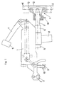
- the terminal box 1 shows the terminal box 1, which is fastened to the rope 3 by means of two jaws 2 while driving.
- the clamping jaws 2 are released from the rope 3 by a mechanism which has a lever 4.
- This carries at its free end a roller 5, which runs onto a stationary rail, not shown, so that the lever 4 is pivoted downward.
- a bearing 6 for an axis 7 is provided on the underside of the terminal box 1.
- the hanger 8 is pivotally mounted, so that the gondola or the seat can swing freely in the direction of travel.
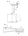
- the axis 7 carries at its free end a guide roller 11 which runs into a guide rail 12. As shown in FIG. 2, this is widened in a funnel shape towards the inlet side, so that it is reliably grasped by the two guide walls 13 even in the event of transverse vibrations of the hanger (FIG. 1a).
- the essentially rigid guide roller 11 is mounted on an axle 7 rigidly connected to the terminal box 1. If the hanger executes transverse vibrations when it moves in, the guide roller 11 moves up and down and, in the process, hits the upper and lower guide walls alternately several times. These shocks occur essentially unsprung, which causes considerable inertia forces between the guide wall 13 and guide roller 11 due to the large moment of inertia of the hanger, which in particular stress the guide roller 11 and the axis 7 and their storage and can lead to the breakage of these parts.
- a possible relatively hard rubber pad on the guide roller which gives way by a maximum of a few millimeters as a result, can hardly reduce these impact forces.
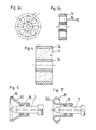
- the guide roller according to the invention according to FIGS. 3a and 3b also has a relatively rigid race 14, which is, however, connected to the hub 15 via individual rubber-elastic spokes 16, for example made of an elastomeric plastic material.
- spokes 16 can fold or compress under the action of a radial force while the opposing spokes are stretched, so that the rim 14 is displaced into an eccentric position.
- the spokes 16 cause both a suspension and a damping, so that a pendulum movement of the Suspension is brought to a standstill without major impacts.
- connection between the race 14 and the hub 15 can also be made by soft foam, e.g. Foam rubber 17 take place.
- the guide roller 11 is designed as a rubber-elastic rotating body made of elastomeric plastic, which has a hub part 18, a race 19 and a suspension part 20 lying in between. 6, this can be made bellows-shaped to increase the suspension possibility even when using a relatively hard plastic material.
- vehicle tires FIG. 8 is also conceivable, the cavity being able to be filled with air or with soft foam.
- the suspension according to the invention can also be achieved with a rigid guide roller 11 in that it is mounted on an axle 7 which can be pivoted about a pin 21.
- the axis 7 is pressed back into its central position after a deflection.
- Damping elements 23 are preferably also provided, which in the exemplary embodiment shown are assembled to form a unit with the springs in the manner of the shock absorbers customary in motor vehicles.
- the use of a torsion spring arranged coaxially with the bolt 7 is also possible.
- a support bar 18 is mounted next to the guide rail 12, on which the hub of the guide roller 11 is supported.
Landscapes
- Engineering & Computer Science (AREA)
- Transportation (AREA)
- Mechanical Engineering (AREA)
- Ropes Or Cables (AREA)
- Flexible Shafts (AREA)
- Platform Screen Doors And Railroad Systems (AREA)
- Manufacturing Of Electric Cables (AREA)
- Near-Field Transmission Systems (AREA)
Applications Claiming Priority (2)
| Application Number | Priority Date | Filing Date | Title |
|---|---|---|---|
| AT0265385A AT385480B (de) | 1985-09-11 | 1985-09-11 | Laufwerkstraeger fuer seilbahnen, insbesondere fuer einseil-umlaufbahnen |
| AT2653/85 | 1985-09-11 |
Publications (3)
| Publication Number | Publication Date |
|---|---|
| EP0218897A2 true EP0218897A2 (fr) | 1987-04-22 |
| EP0218897A3 EP0218897A3 (en) | 1987-08-05 |
| EP0218897B1 EP0218897B1 (fr) | 1990-03-21 |
Family
ID=3538143
Family Applications (1)
| Application Number | Title | Priority Date | Filing Date |
|---|---|---|---|
| EP86112278A Expired - Lifetime EP0218897B1 (fr) | 1985-09-11 | 1986-09-05 | Support d'appareil de roulement pour téléphériques, notamment pour téléphériques monocâbles à boucle fermée |
Country Status (4)
| Country | Link |
|---|---|
| EP (1) | EP0218897B1 (fr) |
| AT (2) | AT385480B (fr) |
| DE (1) | DE3669693D1 (fr) |
| IT (1) | IT208296Z2 (fr) |
Cited By (15)
| Publication number | Priority date | Publication date | Assignee | Title |
|---|---|---|---|---|
| CH678841A5 (en) * | 1989-02-01 | 1991-11-15 | Von Roll Transportsysteme | Rope conveyor with truck - has curving rail for roller on truck-clamp bracket |
| EP0640518A1 (fr) * | 1993-08-25 | 1995-03-01 | Pomagalski S.A. | Dispositif de stabilisation des pinces d'un téléporteur |
| EP1174325B1 (fr) * | 2000-07-20 | 2004-01-14 | Innova Patent GmbH | Train de roulement pour l'élément mouvant d'un installation à téléphérique |
| FR2939394A1 (fr) * | 2008-12-08 | 2010-06-11 | Doppelmayr France | Dispositif de transport par cable muni de moyens d'amortissement. |
| US7891300B2 (en) | 2005-09-29 | 2011-02-22 | High Technology Investments B.V. | Cable derailing prevention device for carrier/traction cables of cable car systems |
| US8082853B2 (en) | 2003-01-30 | 2011-12-27 | High Technology Investments B.V. | Hold-down device for the cable guide in cable-drawn transport systems |
| CN102372005A (zh) * | 2010-08-19 | 2012-03-14 | 因诺瓦专利有限责任公司 | 悬索铁道系统 |
| EP2441638A1 (fr) * | 2010-10-18 | 2012-04-18 | Innova Patent GmbH | Installation de transport par câble |
| US8393276B2 (en) | 2007-08-03 | 2013-03-12 | Rolic Invest S.Ar.L. | Cable transportation system and relative operating method |
| US8408141B2 (en) | 2007-10-26 | 2013-04-02 | Rolic Invest S.Ar.L. | Cable transportation system and relative operating method |
| US8474743B2 (en) | 2009-08-04 | 2013-07-02 | Rolic Invest S.Ar.L. | Ski-lift seat return device |
| US8573132B2 (en) | 2010-07-14 | 2013-11-05 | Rolic International S.Ar.L. | Cable transportation system switch and cable transportation system comprising such a switch |
| US8590458B2 (en) | 2007-04-20 | 2013-11-26 | Rolic Invest S.Ar.L. | Chair-lift |
| US8844446B2 (en) | 2007-04-20 | 2014-09-30 | Rolic International S.Ar.L. | Cable transportation system and relative drive method |
| US8991317B2 (en) | 2009-07-09 | 2015-03-31 | Rolic International S.A.R.L. | Transportation unit for cable transportation systems |
Family Cites Families (4)
| Publication number | Priority date | Publication date | Assignee | Title |
|---|---|---|---|---|
| DE134387C (fr) * | ||||
| AT171834B (de) * | 1951-05-25 | 1952-07-10 | Leopold Girak | Gehängeführung für Seilbahnen |
| JPS5842060B2 (ja) * | 1979-02-05 | 1983-09-16 | 日産自動車株式会社 | 懸垂車両のロ−リング静定装置 |
| US4369714A (en) * | 1979-11-27 | 1983-01-25 | Nissan Motor Co., Ltd. | Cable car docking sway arrester mechanism |
-
1985
- 1985-09-11 AT AT0265385A patent/AT385480B/de active
- 1985-12-19 IT IT8524204U patent/IT208296Z2/it active
-
1986
- 1986-09-05 AT AT86112278T patent/ATE51192T1/de not_active IP Right Cessation
- 1986-09-05 EP EP86112278A patent/EP0218897B1/fr not_active Expired - Lifetime
- 1986-09-05 DE DE8686112278T patent/DE3669693D1/de not_active Expired - Lifetime
Cited By (24)
| Publication number | Priority date | Publication date | Assignee | Title |
|---|---|---|---|---|
| CH678841A5 (en) * | 1989-02-01 | 1991-11-15 | Von Roll Transportsysteme | Rope conveyor with truck - has curving rail for roller on truck-clamp bracket |
| EP0640518A1 (fr) * | 1993-08-25 | 1995-03-01 | Pomagalski S.A. | Dispositif de stabilisation des pinces d'un téléporteur |
| FR2709278A1 (fr) * | 1993-08-25 | 1995-03-03 | Pomagalski Sa | Dispositif de stabilisation des pinces d'un téléporteur. |
| US5515789A (en) * | 1993-08-25 | 1996-05-14 | Pomagalski S.A. | Grip guiding device for aerial cableways |
| EP1174325B1 (fr) * | 2000-07-20 | 2004-01-14 | Innova Patent GmbH | Train de roulement pour l'élément mouvant d'un installation à téléphérique |
| US8082853B2 (en) | 2003-01-30 | 2011-12-27 | High Technology Investments B.V. | Hold-down device for the cable guide in cable-drawn transport systems |
| US7891300B2 (en) | 2005-09-29 | 2011-02-22 | High Technology Investments B.V. | Cable derailing prevention device for carrier/traction cables of cable car systems |
| US9463811B2 (en) | 2007-04-20 | 2016-10-11 | Ropfin B.V. | Cable transportation system and relative drive method |
| US8844446B2 (en) | 2007-04-20 | 2014-09-30 | Rolic International S.Ar.L. | Cable transportation system and relative drive method |
| US8590458B2 (en) | 2007-04-20 | 2013-11-26 | Rolic Invest S.Ar.L. | Chair-lift |
| US8393276B2 (en) | 2007-08-03 | 2013-03-12 | Rolic Invest S.Ar.L. | Cable transportation system and relative operating method |
| US9333876B2 (en) | 2007-08-03 | 2016-05-10 | Ropfin B.V. | Cable transportation system and relative operating method |
| US8534196B2 (en) | 2007-08-03 | 2013-09-17 | Rolic Invest S.Ar.L | Cable transportation system and relative operating method |
| US8408141B2 (en) | 2007-10-26 | 2013-04-02 | Rolic Invest S.Ar.L. | Cable transportation system and relative operating method |
| FR2939394A1 (fr) * | 2008-12-08 | 2010-06-11 | Doppelmayr France | Dispositif de transport par cable muni de moyens d'amortissement. |
| WO2010066712A1 (fr) * | 2008-12-08 | 2010-06-17 | Doppelmayr France | Dispositif de transport par cable muni de moyens d'amortissement |
| US9738290B2 (en) | 2009-07-09 | 2017-08-22 | Ropfin B.V. | Transportation unit for cable transportation systems |
| US8991317B2 (en) | 2009-07-09 | 2015-03-31 | Rolic International S.A.R.L. | Transportation unit for cable transportation systems |
| US8474743B2 (en) | 2009-08-04 | 2013-07-02 | Rolic Invest S.Ar.L. | Ski-lift seat return device |
| US8573132B2 (en) | 2010-07-14 | 2013-11-05 | Rolic International S.Ar.L. | Cable transportation system switch and cable transportation system comprising such a switch |
| CN102372005A (zh) * | 2010-08-19 | 2012-03-14 | 因诺瓦专利有限责任公司 | 悬索铁道系统 |
| CN102372005B (zh) * | 2010-08-19 | 2016-01-13 | 因诺瓦专利有限责任公司 | 悬索铁道系统 |
| JP2012086835A (ja) * | 2010-10-18 | 2012-05-10 | Innova Patent Gmbh | 索道システム |
| EP2441638A1 (fr) * | 2010-10-18 | 2012-04-18 | Innova Patent GmbH | Installation de transport par câble |
Also Published As
| Publication number | Publication date |
|---|---|
| ATA265385A (de) | 1987-09-15 |
| EP0218897B1 (fr) | 1990-03-21 |
| EP0218897A3 (en) | 1987-08-05 |
| IT8524204V0 (it) | 1985-12-19 |
| AT385480B (de) | 1988-04-11 |
| DE3669693D1 (de) | 1990-04-26 |
| IT208296Z2 (it) | 1988-05-28 |
| ATE51192T1 (de) | 1990-04-15 |
Similar Documents
| Publication | Publication Date | Title |
|---|---|---|
| EP0218897B1 (fr) | Support d'appareil de roulement pour téléphériques, notamment pour téléphériques monocâbles à boucle fermée | |
| DE3002672C2 (de) | Wagen für Schwebebahnen | |
| AT405166B (de) | Drehgestell-fahrwerk für ein schienenfahrzeug | |
| WO2017037085A1 (fr) | Dispositif de levage | |
| DE2329423C3 (de) | Fahrzeug für eine Volksbelustigungsvorrichtung nach Art einer Achterbahn | |
| EP0589864A1 (fr) | Automotrice, en particulier automotrice ferroviaire | |
| DE4122741A1 (de) | Drehgestell fuer schnellauffaehige schienenfahrzeuge | |
| EP0016469A1 (fr) | Dispositif de montage élastique d'une superstructure rigide sur un châssis déformable de véhicule | |
| AT390422B (de) | Hub- und senkstation fuer haengebahnen | |
| CH658431A5 (en) | Waggon suspension for rail vehicle | |
| DE1195795B (de) | Drehgestell fuer Schienenfahrzeuge mit luft-bereiften Laufraedern und seitlichen Fuehrungen | |
| EP0915001B1 (fr) | Connexion entre caisses des wagons | |
| DE2106662C3 (de) | Antrieb für elektrische Triebfahrzeuge | |
| DE1913784A1 (de) | Radsatzfuehrung fuer Fahrzeuge,insbesondere Schienenfahrzeuge | |
| DE9408846U1 (de) | Tragvorrichtung | |
| DE3409158A1 (de) | Halterungsanordnung von bremsklotzeinheiten an schienenfahrzeugen | |
| DE3827281C2 (fr) | ||
| EP0299318A2 (fr) | Train de roulement pour véhicule ferroviaire avec frein de voie magnétique ou à frein à courants de Foucault | |
| DE19810697A1 (de) | Vorrichtung zur Übertragung der Längskräfte eines Drehgestelles auf den Wagenkasten eines Schienenfahrzeuges, insbesondere eines Triebfahrzeuges mit hoher Zugkraft | |
| DE433529C (de) | Laufradlagerung bei Haengeschnellbahnfahrzeugen | |
| DE19725174C2 (de) | Aufhängung einer Schienenbremse an einem Drehgestell eines Schienenfahrzeuges | |
| DE69101290T2 (de) | Neigbares Fahrzeug. | |
| DE69104231T2 (de) | Futtertrogversorgungseinrichtung. | |
| AT396577B (de) | Fahrbetriebsmittel, insbesondere für eine einseilumlaufbahn | |
| DE943171C (de) | Progressive Federung fuer Schienenfahrzeuge mittels eines Federbandes, das aus einerVielzahl von federnden Draehten oder duennwandigen Lamellen zusammengesetzt ist |
Legal Events
| Date | Code | Title | Description |
|---|---|---|---|
| PUAI | Public reference made under article 153(3) epc to a published international application that has entered the european phase |
Free format text: ORIGINAL CODE: 0009012 |
|
| AK | Designated contracting states |
Kind code of ref document: A2 Designated state(s): AT CH DE IT LI SE |
|
| RAP1 | Party data changed (applicant data changed or rights of an application transferred) |
Owner name: KONRAD DOPPELMAYR & SOHN MASCHINENFABRIK GESELLSCH |
|
| PUAL | Search report despatched |
Free format text: ORIGINAL CODE: 0009013 |
|
| RHK1 | Main classification (correction) |
Ipc: B61B 12/04 |
|
| AK | Designated contracting states |
Kind code of ref document: A3 Designated state(s): AT CH DE IT LI SE |
|
| 17P | Request for examination filed |
Effective date: 19871230 |
|
| 17Q | First examination report despatched |
Effective date: 19890410 |
|
| GRAA | (expected) grant |
Free format text: ORIGINAL CODE: 0009210 |
|
| AK | Designated contracting states |
Kind code of ref document: B1 Designated state(s): AT CH DE IT LI SE |
|
| PG25 | Lapsed in a contracting state [announced via postgrant information from national office to epo] |
Ref country code: IT Free format text: LAPSE BECAUSE OF FAILURE TO SUBMIT A TRANSLATION OF THE DESCRIPTION OR TO PAY THE FEE WITHIN THE PRE;WARNING: LAPSES OF ITALIAN PATENTS WITH EFFECTIVE DATE BEFORE 2007 MAY HAVE OCCURRED AT ANY TIME BEFORE 2007. THE CORRECT EFFECTIVE DATE MAY BE DIFFERENT FROM THE ONE RECORDED.SCRIBED TIME-LIMIT Effective date: 19900321 Ref country code: SE Effective date: 19900321 |
|
| REF | Corresponds to: |
Ref document number: 51192 Country of ref document: AT Date of ref document: 19900415 Kind code of ref document: T |
|
| REF | Corresponds to: |
Ref document number: 3669693 Country of ref document: DE Date of ref document: 19900426 |
|
| PG25 | Lapsed in a contracting state [announced via postgrant information from national office to epo] |
Ref country code: CH Effective date: 19900930 Ref country code: LI Effective date: 19900930 |
|
| PLBE | No opposition filed within time limit |
Free format text: ORIGINAL CODE: 0009261 |
|
| STAA | Information on the status of an ep patent application or granted ep patent |
Free format text: STATUS: NO OPPOSITION FILED WITHIN TIME LIMIT |
|
| 26N | No opposition filed | ||
| REG | Reference to a national code |
Ref country code: CH Ref legal event code: PL |
|
| PGFP | Annual fee paid to national office [announced via postgrant information from national office to epo] |
Ref country code: DE Payment date: 19950127 Year of fee payment: 9 |
|
| PG25 | Lapsed in a contracting state [announced via postgrant information from national office to epo] |
Ref country code: DE Effective date: 19960601 |
|
| PGFP | Annual fee paid to national office [announced via postgrant information from national office to epo] |
Ref country code: AT Payment date: 20050914 Year of fee payment: 20 |