EP0219095A2 - Einrichtung zum Wegblasen des Fadenendes von einer vollen Kreuzspirale, die auf einer Open-end-Spinnmaschine geformt wurde - Google Patents
Einrichtung zum Wegblasen des Fadenendes von einer vollen Kreuzspirale, die auf einer Open-end-Spinnmaschine geformt wurde Download PDFInfo
- Publication number
- EP0219095A2 EP0219095A2 EP86114209A EP86114209A EP0219095A2 EP 0219095 A2 EP0219095 A2 EP 0219095A2 EP 86114209 A EP86114209 A EP 86114209A EP 86114209 A EP86114209 A EP 86114209A EP 0219095 A2 EP0219095 A2 EP 0219095A2
- Authority
- EP
- European Patent Office
- Prior art keywords
- full cheese
- full
- cheese
- thread
- pipe conduit
- Prior art date
- Legal status (The legal status is an assumption and is not a legal conclusion. Google has not performed a legal analysis and makes no representation as to the accuracy of the status listed.)
- Withdrawn
Links
- 235000013351 cheese Nutrition 0.000 title claims abstract description 60
- 238000007383 open-end spinning Methods 0.000 title claims abstract description 13
- 238000007664 blowing Methods 0.000 title claims abstract description 6
- 238000004804 winding Methods 0.000 claims abstract description 24
- 238000009987 spinning Methods 0.000 claims description 8
- 230000015572 biosynthetic process Effects 0.000 claims description 2
- 238000002347 injection Methods 0.000 description 11
- 239000007924 injection Substances 0.000 description 11
- 230000002093 peripheral effect Effects 0.000 description 2
- 240000002129 Malva sylvestris Species 0.000 description 1
- 235000006770 Malva sylvestris Nutrition 0.000 description 1
- 239000000835 fiber Substances 0.000 description 1
- 239000000463 material Substances 0.000 description 1
- 229910052709 silver Inorganic materials 0.000 description 1
- 239000004332 silver Substances 0.000 description 1
Images



Classifications
-
- D—TEXTILES; PAPER
- D01—NATURAL OR MAN-MADE THREADS OR FIBRES; SPINNING
- D01H—SPINNING OR TWISTING
- D01H9/00—Arrangements for replacing or removing bobbins, cores, receptacles, or completed packages at paying-out or take-up stations ; Combination of spinning-winding machine
- D01H9/18—Arrangements for replacing or removing bobbins, cores, receptacles, or completed packages at paying-out or take-up stations ; Combination of spinning-winding machine for supplying bobbins, cores, receptacles, or completed packages to, or transporting from, paying-out or take-up stations ; Arrangements to prevent unwinding of roving from roving bobbins
-
- B—PERFORMING OPERATIONS; TRANSPORTING
- B65—CONVEYING; PACKING; STORING; HANDLING THIN OR FILAMENTARY MATERIAL
- B65H—HANDLING THIN OR FILAMENTARY MATERIAL, e.g. SHEETS, WEBS, CABLES
- B65H67/00—Replacing or removing cores, receptacles, or completed packages at paying-out, winding, or depositing stations
- B65H67/08—Automatic end-finding and material-interconnecting arrangements
- B65H67/086—Preparing supply packages
-
- B—PERFORMING OPERATIONS; TRANSPORTING
- B65—CONVEYING; PACKING; STORING; HANDLING THIN OR FILAMENTARY MATERIAL
- B65H—HANDLING THIN OR FILAMENTARY MATERIAL, e.g. SHEETS, WEBS, CABLES
- B65H2701/00—Handled material; Storage means
- B65H2701/30—Handled filamentary material
- B65H2701/31—Textiles threads or artificial strands of filaments
Definitions
- the invention generally relates to an open-end spinning and winding machine and, particularly, to an apparatus for making a thread end noticeable and distinguishable from a reel of threads wound fully around a bobbin (hereinafter referred to as a full cheese) by the open-end spinning and winding machine. More specifically, the apparatus dislocated the direction and position of an end of a thread by blowing off the end of the thread wound at a certain angle with respect to the bobbin in the axial direction, thereof.
- a thread spun by an open-end spinning and winding machine is wound around a bobbin to be formed in a full cheese.
- a thread is wound around a bobbin 20 at angles ⁇ 1 and ⁇ 2 with respect to the axial direction of the bobbin 20.
- a silver which is string-shape fiber to be supplied with a spinning and winding machine as a material for the thread is no longer supplied to the spinning and winding machine. Accordingly, the thread wound tightly on the surface of a full cheese tapers at its end.
- the winding direction of the tapered portion does not change, i.e., ⁇ 1 and ⁇ 2.
- a full cheese thus formed and removed from the spinning and winding machine is used for various purposes, including being fed to a wrapper. In this case, it is always necessary to lift a thread end from the surface of a full cheese.
- the invention has been developed in view of the disadvantage described above. It is therefore the object of the present invention to provide an apparatus which dislocates a thread end from a full cheese transported from an open-end spinning and winding machine so that the thread end can be found easily.
- An apparatus comprises a pipe conduit which allows a full cheese, discharged and transported from an open-end spinning and winding machine, to pass therethrough and nozzles which inject high speed air from the inner surface of the pipe conduit toward the outer surface of the full cheese.
- the pipe conduit is installed halfway on the transport path of the full cheese.
- the inner diameter of the pipe conduit is set to form an air flow path, which maintains the speed of air current injected from the nozzle, between the outer surface of the full cheese and the inner surface of the pipe conduit.
- the nozzles are disposed at the exit side of the pipe conduit.
- the direction in which high speed air is injected is the resultant direction opposite to the direction in which the full cheese is transported and the direction opposite to the direction in which the thread is wound on the full cheese.
- air is injected at high speed from nozzles toward the outer surface of a full cheese when it passes through a pipe conduit, while it is being transported. Since the injection direction of the high speed air is opposite to the thread winding direction, an injected air blows the thread end from the full cheese surface. Moreover, since the air injection direction is also opposite to the direction in which the full cheese is transported, the thread end which has been raised from the full cheese surface flutters backward from the full cheese (the direction in which the full cheese is transported is set to the front). In detail, the air swirls at high speed around the full cheese, with the result that the wound thread unwinds. If the pipe conduit has sufficient length, the thread end which has been raised from surface of the cheese is unwound and blown downwardly and rearwardly from the pipe conduit.
- the end of a thread of the full cheese which was wound in a certain direction with the axial direction of a bobbin is dislocated according to an apparatus of the present invention.
- the thread end can be distinguished from a reel of the thread and located easily.
- Fig. 1 is a side view of an apparatus of the present invention installed on an open-end spinning and winding machine.
- Fig. 2 is a plan view of the apparatus.
- numeral 1 shows a full cheese which is discharged from a spinning and winding machine (not shown) and transported by the belt conveyor 2.
- a short pipe 3 is disposed halfway on the belt conveyor 2.
- the short pipe 3 has nozzles 4 at the outlet side thereof which inject air at high speed.
- the belt conveyor 2 extends to the end of the spinning and winding machine table 5.
- a roller conveyor 6 is connected to the left end of the belt conveyor 2, as shown in Figs. 1 and 2, to further transport the full cheese. As shown in Fig. 2, roller conveyors 6 are provided in two rows.
- numeral 7 is a sensor which detects the full cheese 1 when it is placed on the roller conveyor 6.
- Numeral 8 designates a nozzle which injects air at high speed from approximately the center of the roller conveyor 6 upward toward the full bobbin cheese 1 in the direction opposite to the direction in which the full cheese is transported in response to a signal transmitted from the sensor 7.
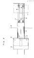
- Fig. 3 is an enlarged sectional view showing the principal portions of the short pipe 3 and the nozzle 4.
- the short pipe 3 is removed at the bottom portion which would otherwise be brought into contact with the belt conveyor 2, and is mounted on the spinning and winding machine table 5 so as to form a tunnel on the transport path.
- the inner diameter (a) of the short pipe 3 is large enough for the full cheese 1 to pass through it on the conveyor 2. It is set to allow a passage of the full cheese 1 considering the possibility of formation of full cheeses having large diameters.
- the inner diameter (a) of the short pipe 3 is set to be larger than the outer diameter (b) of the full cheese so that the flow speed of high speed air which is described below can be fast enough to blow off the thread end on the full cheese 1.
- the nozzles 4 are provided at the inner face of the short pipe 3 circumferentially thereof at equal intervals. Five nozzles 4 are mounted on the short pipe 3, in this embodiment.
- High speed air injected from each nozzle 4 swirls around the outer surface of the full cheese 1 which passes through the short pipe 3, i.e., the high speed air is injected from the nozzles 4 against not only the thread winding direction, namely, counterclockwise, but also to the direction in which the full cheese 1 is carried, namely, from the exit side of the short pipe 3 to its entrance side.
- nozzles 4 are numbered 4a, 4b, 3c, 4d, and 4e counterclockwise from the lower right.
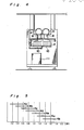
- Fig. 4 schematically illustrates the peripheral structure of an apparatus of the present invention installed on a spinning and winding machine.
- An open-end spinning and winding machine has two transport paths.
- Two apparatuses according to the present invention are installed on each transport path as shown in this drawing.
- Nozzles 4 and 8 are connected to their corresponding highly pressurized air supplying pipes 9, respectively.
- the highly pressurized air supplying pipes 9 are connected to electromagnetic valves 10 which have a function of distributing highly pressurized air.
- a compressor (not shown) supplies highly pressurized air to the electromagnetic valves 10.
- Valves which correspond to each nozzle 4a, 4b, 4c, 4d, and 4e open and close repeatedly and sequentially at a predetermined time cycle.
- Fig. 5 is a graph showing the injection time cycle of each nozzle.
- the nozzle 4a injects highly pressurized air for 0.5 seconds.
- the nozzle 4b starts injection 0.2 seconds after the nozzle 4a started injection.
- Other nozzles make sequential injection in the same manner.
- the control box 11 shown in Fig. 4 controls the injection cycle. It is possible to start injection simultaneously from the nozzles. In this case, however, it is necessary to install a pressure tank or a compressor with high output capacity. Sequential injection is more suitable than simultaneous injection because it makes high speed air current more turbulent and ensures the blowing-off of the thread end.
- the valve, of the electromagnetic valve 10, which corresponds to the nozzle 8 opens and closes in response to the signal transmitted from the sensor 7.
- the nozzle 8 is provided to blow off a thread end on the roller conveyor 6 considering a case where the thread end on the full cheese 1 fails to be blown off by the nozzle 4 because the thread end is sandwiched between the full cheese 1 and the belt conveyor 2.
- part of the short pipe 3 is removed at the portion where the short pipe 3 would otherwise come in contact with the belt conveyor 2.
- a short circular pipe may be used with no lower portion thereof removed.
- the nozzles 4 alone can reliably blow off the thread end, so that the need for providing the nozzle 8, which compensates for the failure of blowing-off the thread end, is eliminated.
- the invention may be embodied by the tandem provision of two apparatuses on the transport path so as to blow off a thread end reliably by rotating a full cheese at a certain angle when it moves from one apparatus to the other.
Landscapes
- Engineering & Computer Science (AREA)
- Mechanical Engineering (AREA)
- Textile Engineering (AREA)
- Spinning Or Twisting Of Yarns (AREA)
- Replacing, Conveying, And Pick-Finding For Filamentary Materials (AREA)
Applications Claiming Priority (2)
| Application Number | Priority Date | Filing Date | Title |
|---|---|---|---|
| JP229378/85 | 1985-10-14 | ||
| JP60229378A JPS6290338A (ja) | 1985-10-14 | 1985-10-14 | オ−プンエンド精紡機における満管チ−ズの糸尻吹き払い装置 |
Publications (2)
| Publication Number | Publication Date |
|---|---|
| EP0219095A2 true EP0219095A2 (de) | 1987-04-22 |
| EP0219095A3 EP0219095A3 (de) | 1987-12-16 |
Family
ID=16891236
Family Applications (1)
| Application Number | Title | Priority Date | Filing Date |
|---|---|---|---|
| EP86114209A Withdrawn EP0219095A3 (de) | 1985-10-14 | 1986-10-14 | Einrichtung zum Wegblasen des Fadenendes von einer vollen Kreuzspirale, die auf einer Open-end-Spinnmaschine geformt wurde |
Country Status (3)
| Country | Link |
|---|---|
| US (1) | US4705224A (de) |
| EP (1) | EP0219095A3 (de) |
| JP (1) | JPS6290338A (de) |
Cited By (2)
| Publication number | Priority date | Publication date | Assignee | Title |
|---|---|---|---|---|
| EP0322008A1 (de) * | 1987-12-18 | 1989-06-28 | SAVIO S.p.A. | Vorrichtung zum Aufsuchen eines gerissenen Fadenendes auf einer im Aufbau befindlichen Fadenwicklung |
| EP0347535A1 (de) * | 1988-06-24 | 1989-12-27 | W. SCHLAFHORST AG & CO. | Verfahren und Einrichtung zum pneumatischen Erfassen und Überkopfabziehen des Fadenendes eines Kopses |
Families Citing this family (3)
| Publication number | Priority date | Publication date | Assignee | Title |
|---|---|---|---|---|
| JPH0729728B2 (ja) * | 1986-10-24 | 1995-04-05 | 村田機械株式会社 | パッケ−ジの糸処理装置 |
| US4858836A (en) * | 1986-12-12 | 1989-08-22 | Murata Kikai Kabushiki Kaisha | Yarn end finding device |
| BE1003538A3 (nl) * | 1989-10-06 | 1992-04-14 | Picanol Nv | Inrichting voor het vastnemen van het draadeinde aan een garenvoorraadspoel. |
Family Cites Families (9)
| Publication number | Priority date | Publication date | Assignee | Title |
|---|---|---|---|---|
| US3236464A (en) * | 1962-02-03 | 1966-02-22 | Reiners Walter | Device for removing a starting length of yarn from a textile coil |
| DE1560568C3 (de) * | 1965-05-29 | 1974-10-10 | Reiners, Walter, Dr.-Ing., 4050 Moenchengladbach | Vorrichtung zum Erfassen des Fadenanfanges eines Kopses |
| US3441230A (en) * | 1966-05-27 | 1969-04-29 | Reiners Walter | Pneumatic device for seizing a starting length of yarn wound on a cop |
| US3637148A (en) * | 1966-11-30 | 1972-01-25 | Reiners Walter | Device for pneumatically removing the tip or foot bunch from supply coils |
| DE2230801A1 (de) * | 1972-06-23 | 1974-01-17 | Schlafhorst & Co W | Automatische spulmaschine |
| JPS508255U (de) * | 1973-05-23 | 1975-01-28 | ||
| JPS553132Y2 (de) * | 1974-05-30 | 1980-01-25 | ||
| DE2528281C2 (de) * | 1975-06-25 | 1984-10-04 | W. Schlafhorst & Co, 4050 Mönchengladbach | Vorrichtung zum Lösen und/oder Entfernen der Ober- und/oder Unterwindungen und/oder Fadenenden von Textilspulen |
| DE3244378A1 (de) * | 1982-12-01 | 1984-08-30 | W. Schlafhorst & Co, 4050 Mönchengladbach | Vorrichtung zum ablegen und einbehalten des fadenendes in der spulenhuelse eines von einer kopsvorbereitungsstation an ein transportmittel weitergegebenen spinnkopses |
-
1985
- 1985-10-14 JP JP60229378A patent/JPS6290338A/ja active Granted
-
1986
- 1986-10-14 US US06/918,104 patent/US4705224A/en not_active Expired - Fee Related
- 1986-10-14 EP EP86114209A patent/EP0219095A3/de not_active Withdrawn
Cited By (2)
| Publication number | Priority date | Publication date | Assignee | Title |
|---|---|---|---|---|
| EP0322008A1 (de) * | 1987-12-18 | 1989-06-28 | SAVIO S.p.A. | Vorrichtung zum Aufsuchen eines gerissenen Fadenendes auf einer im Aufbau befindlichen Fadenwicklung |
| EP0347535A1 (de) * | 1988-06-24 | 1989-12-27 | W. SCHLAFHORST AG & CO. | Verfahren und Einrichtung zum pneumatischen Erfassen und Überkopfabziehen des Fadenendes eines Kopses |
Also Published As
| Publication number | Publication date |
|---|---|
| US4705224A (en) | 1987-11-10 |
| EP0219095A3 (de) | 1987-12-16 |
| JPH0327647B2 (de) | 1991-04-16 |
| JPS6290338A (ja) | 1987-04-24 |
Similar Documents
| Publication | Publication Date | Title |
|---|---|---|
| US7269936B2 (en) | Spinning device and method for detecting fiber accumulated state | |
| EP1184495B1 (de) | Maschine und Verfahren zur Herstellung eines Kerngarnes | |
| US20030167747A1 (en) | Device for the pneumatic joining of yarns | |
| EP1316631B1 (de) | Spinnvorrichtung und -verfahren | |
| US3423000A (en) | Device for accumulating filaments during spool-change | |
| KR100260219B1 (ko) | 방적방법 및 방적장치 | |
| US4503662A (en) | Method and apparatus for yarn piecing in fasciated yarn spinning | |
| US4446687A (en) | Pneumatic yarn splicing apparatus for splicing core spun yarns | |
| US4705224A (en) | Apparatus for blowing a thread end off of a full cheese formed by an open-end spinning and winding machine | |
| US4074871A (en) | Method and apparatus for handling strands | |
| US4833872A (en) | Method and apparatus for air splicing yarn in a textile creel | |
| US5494231A (en) | Method and apparatus for finding and feeding a yarn end to be taken up in a textile winder | |
| JPS5816670A (ja) | 喫煙可能な物品のためのフイルタロツドを造るための方法および装置 | |
| JPH0665583B2 (ja) | 糸端口出し装置 | |
| US4999891A (en) | Yarn handling device and method | |
| JPH02266B2 (de) | ||
| JPH0615927Y2 (ja) | 合糸機の下糸引出し装置 | |
| JPH0959831A (ja) | パッケージからの糸端吸引装置 | |
| JP4486306B2 (ja) | 線条用エアーダンサ装置 | |
| JP3572770B2 (ja) | 空気式糸継装置 | |
| JPH052527Y2 (de) | ||
| JPS6348705Y2 (de) | ||
| JPH1072170A (ja) | 精紡管糸の口出し装置 | |
| JPS60157465A (ja) | 糸条継足し方法およびその装置 | |
| JPH0649740A (ja) | 無杼織機の緯入れノズルへの緯糸通し装置 |
Legal Events
| Date | Code | Title | Description |
|---|---|---|---|
| PUAI | Public reference made under article 153(3) epc to a published international application that has entered the european phase |
Free format text: ORIGINAL CODE: 0009012 |
|
| AK | Designated contracting states |
Kind code of ref document: A2 Designated state(s): CH DE GB IT LI |
|
| PUAL | Search report despatched |
Free format text: ORIGINAL CODE: 0009013 |
|
| AK | Designated contracting states |
Kind code of ref document: A3 Designated state(s): CH DE GB IT LI |
|
| 17P | Request for examination filed |
Effective date: 19880608 |
|
| 17Q | First examination report despatched |
Effective date: 19900124 |
|
| STAA | Information on the status of an ep patent application or granted ep patent |
Free format text: STATUS: THE APPLICATION IS DEEMED TO BE WITHDRAWN |
|
| 18D | Application deemed to be withdrawn |
Effective date: 19900804 |
|
| RIN1 | Information on inventor provided before grant (corrected) |
Inventor name: AKIYAMA, SHIGEO Inventor name: SATOU, SHIGEJI |