EP0322008A1 - Vorrichtung zum Aufsuchen eines gerissenen Fadenendes auf einer im Aufbau befindlichen Fadenwicklung - Google Patents
Vorrichtung zum Aufsuchen eines gerissenen Fadenendes auf einer im Aufbau befindlichen Fadenwicklung Download PDFInfo
- Publication number
- EP0322008A1 EP0322008A1 EP88202694A EP88202694A EP0322008A1 EP 0322008 A1 EP0322008 A1 EP 0322008A1 EP 88202694 A EP88202694 A EP 88202694A EP 88202694 A EP88202694 A EP 88202694A EP 0322008 A1 EP0322008 A1 EP 0322008A1
- Authority
- EP
- European Patent Office
- Prior art keywords
- yarn
- package
- formation cone
- suction
- blowing nozzles
- Prior art date
- Legal status (The legal status is an assumption and is not a legal conclusion. Google has not performed a legal analysis and makes no representation as to the accuracy of the status listed.)
- Granted
Links
- 230000015572 biosynthetic process Effects 0.000 claims abstract description 28
- 238000007664 blowing Methods 0.000 claims abstract description 20
- 238000009987 spinning Methods 0.000 claims abstract description 15
- 230000007246 mechanism Effects 0.000 claims description 13
- 230000003287 optical effect Effects 0.000 claims description 8
- 230000009471 action Effects 0.000 claims description 7
- 230000004888 barrier function Effects 0.000 claims description 7
- 238000007378 ring spinning Methods 0.000 claims description 6
- 230000003534 oscillatory effect Effects 0.000 claims description 4
- 238000004804 winding Methods 0.000 claims description 3
- 230000008878 coupling Effects 0.000 claims description 2
- 238000010168 coupling process Methods 0.000 claims description 2
- 238000005859 coupling reaction Methods 0.000 claims description 2
- 230000005684 electric field Effects 0.000 claims description 2
- 238000010008 shearing Methods 0.000 claims description 2
- 239000004753 textile Substances 0.000 description 7
- 238000005520 cutting process Methods 0.000 description 4
- 230000000694 effects Effects 0.000 description 3
- 238000004519 manufacturing process Methods 0.000 description 3
- 230000008901 benefit Effects 0.000 description 2
- 230000006872 improvement Effects 0.000 description 2
- 239000010410 layer Substances 0.000 description 2
- 238000000034 method Methods 0.000 description 2
- 230000004048 modification Effects 0.000 description 2
- 238000012986 modification Methods 0.000 description 2
- 230000000717 retained effect Effects 0.000 description 2
- 235000014676 Phragmites communis Nutrition 0.000 description 1
- 238000007792 addition Methods 0.000 description 1
- 230000001174 ascending effect Effects 0.000 description 1
- 230000001939 inductive effect Effects 0.000 description 1
- 230000000977 initiatory effect Effects 0.000 description 1
- 238000005304 joining Methods 0.000 description 1
- 239000000463 material Substances 0.000 description 1
- 238000002360 preparation method Methods 0.000 description 1
- 230000009467 reduction Effects 0.000 description 1
- 238000005096 rolling process Methods 0.000 description 1
- 238000000926 separation method Methods 0.000 description 1
- 239000002344 surface layer Substances 0.000 description 1
- 229920002994 synthetic fiber Polymers 0.000 description 1
- 230000009466 transformation Effects 0.000 description 1
Images

Classifications
-
- D—TEXTILES; PAPER
- D01—NATURAL OR MAN-MADE THREADS OR FIBRES; SPINNING
- D01H—SPINNING OR TWISTING
- D01H15/00—Piecing arrangements ; Automatic end-finding, e.g. by suction and reverse package rotation; Devices for temporarily storing yarn during piecing
-
- B—PERFORMING OPERATIONS; TRANSPORTING
- B65—CONVEYING; PACKING; STORING; HANDLING THIN OR FILAMENTARY MATERIAL
- B65H—HANDLING THIN OR FILAMENTARY MATERIAL, e.g. SHEETS, WEBS, CABLES
- B65H67/00—Replacing or removing cores, receptacles, or completed packages at paying-out, winding, or depositing stations
- B65H67/08—Automatic end-finding and material-interconnecting arrangements
-
- B—PERFORMING OPERATIONS; TRANSPORTING
- B65—CONVEYING; PACKING; STORING; HANDLING THIN OR FILAMENTARY MATERIAL
- B65H—HANDLING THIN OR FILAMENTARY MATERIAL, e.g. SHEETS, WEBS, CABLES
- B65H2701/00—Handled material; Storage means
- B65H2701/30—Handled filamentary material
- B65H2701/31—Textiles threads or artificial strands of filaments
Definitions
- This invention relates to a device for seeking and withdrawing a broken yarn end on a forming package in order to unwind a yarn length sufficient to allow the rejoining operation to take place for automatically reinstating the spinning process in a continuous ring spinning machine.
- Said known devices either do not ensure perfect preparation of the yarn under all conditions, or require a considerable use of blown air, or comprise blowing nozzles or sucker elements mounted in a fixed position and therefore unable to be operationally adapted to the variable position of the formation cone on whose surface the broken yarn end to be withdrawn is retained. It is apparent that in this latter case the separation action of the blower nozzles or sucker elements extends only partly over the surface of the formation cone, or in the limit not at all, with the result that the yarn withdrawal device does not operate effectively.
- blower and/or sucker elements aided by blades of various materials which rub against the package surface, ie against the wound yarn layers, in an attempt to release the broken yarn end.
- the object of the present invention is to provide a device by which the broken yarn end adhering to the surface of the package formation cone is reliably released and at the same time a yarn portion of sufficient length is unwound to complete the rejoining cycle by which the spinning operation can go to completion.
- a further advantage of the device compared with the known art is its constructional simplicity which allows the necessary adjustments to be easily made as the geometrical parameters of the forming package vary and as the type of yarn being wound varies.
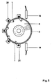
- the device of the present invention which comprises: - a series of blowing nozzles disposed substantially in a helical arc about the package formation cone; - a suction cap which is located above the air jets produced by said nozzles and gradually tapers from the bottom upwards to connect into a suction duct having a straightened length substantially equal to the length of yarn required to be unwound and sucked from the package for the subsequent rejoining operation needed to automatically reinstate the spinning process; - a block into which said suction duct opens and which has a first zone for sensing the yarn by means of a yarn-sensing light barrier or electric field and a second zone controlled by the first for shearing the end of the sucked yarn; - two opposing frontal optical sensors which produce a barrier light beam for sensing the presence of the package formation cone in order to position it along the helical arc of the blowing nozzles.
- the device also comprises a control mechanism arranged both to vertically move the package support peg upwards or downwards and to intermittently rotate said support peg to subject the entire surface of the formation cone to the action of the air jets from the blowing nozzles.
- control source for rotating the peg and thus the bobbin provides two rotary movements: firstly a slow rotation for seeking the end of the yarn and extricating it from the wound layers of the formation cone, and then a sufficiently rapid rotation to release into the suction duct the yarn length required for rejoining, this rapidity resulting not only in a reduction in the cycle time but also preventing the yarn fibrillating substantially under the action of the air stream.
- the pipes of the blowing nozzles are coupled to guide supports, these latter fixed to the outer surface of the suction cap, said coupling allowing the pipes both to slide vertically and to rotate angularly to be able to perfectly adjust the operating directions of the air jets blowing against the zone in which the broken yarn end is to be found, on the basis of the dimensions of the package formation cone and the type of yarn wound.
- control mechanism located at the base of the package support is able to generate an oscillatory reciprocating motion of limited amplitude straddling the position which the formation cone has assumed, this being done while the package is being rotated about its axis and in the opposite direction to the yarn winding.
- 1 is one of the blowing nozzles which operate by blowing jets of air onto the surface of the formation cone; 2 is the position-adjustable pipe of the blowing nozzles; 3 is the suction cap under which the upper end of the package 7 is located. Said cap tapers upperly to engage the suction duct 6; 4 is the block containing the sensing members for the yarn 8 and the cutting element 12.
- This block is the source of an air stream for conveying the end of the yarn 8 through the photo-electric or inductive sensor 9 and into the gap between the cutting blades of the scissor elements 12;
- 5 is the package formation cone on the surface of which the broken yarn end is retained;
- 6 is the suction duct, which is of length substantially equal to the length of yarn to be unwound and sucked from the package, and connects the suction cap 3 to the block 4;
- 7 is the package under formation, on the cone 5 of which the broken yarn end is sought;
- 8 is the yarn sucked from the package 7 and unwound by a length sufficient to allow the sucked yarn to be sensed by a light barrier 10;
- 11 is the peg which holds the forming package 7;
- 12 are the scissor elements for removing the excess yarn so that the portion of sucked yarn 8 is of a suitable length for rejoining as required for reinstatement of the spinning process;
- 14 are the two optical sensors, one emitting and one receiving,
- Said mechanism is also able to generate, pneumatically or electrically, a reciprocating oscillatory movement of limited amplitude about the position established by the optical sensors 14 to enable the formation cone 5 to be struck by the air jets more effectively;
- 16 is the locking screw for the pipe 2 which when slackened allows exact positioning of the blowing nozzle 1 such that the air jet strikes the formation cone with high efficiency and in collaboration with the other nozzles;
- 18 is the direction of rotation of the support peg 11 and thus of the package 7, this direction being advantageously the opposite of that in which the yarn 8 is wound onto the forming package 7;
- 20 is the arrow indicating the vertical raising of the package 7 until its formation cone interrupts the light beam extending between the optical sensors 14;
- 21 is the guide support for the pipe 2 and is fixed to the outer surface of the suction cap 3.
- Said carriage is mobile along the spinning face on runways comprising one or more rails of any shape, cooperating with suitable rolling means such as wheels, rollers or equivalent means.
- suitable rolling means such as wheels, rollers or equivalent means.
- the yarn rejoining carriage is driven to and fro to patrol along the spindles.
- the carriage apparatus checks by sensor means of the known art whether the yarn is present or not in each spinning spindle.
- the blowing nozzles 1 When the light beam is intercepted the blowing nozzles 1 are activated and at substantially the same time the control mechanism 15 effects the rotation 18 and suction is applied to the cap 3 and duct 8, this latter being connected to a vacuum pump or similar member, or to any air suction main.
- the rotation 18 of the package 7 enables its entire frusto-conical surface 5 to be effectively exposed to the air jets leaving the nozzles 1, which by virtue of their overall helical arc arrangement create an air current of ascending vortex type.
- Said rotation 18 of the package 7 is advantageously of increasing intensity, ie initially it comprises a few slow rotations necessary to give the blowing nozzles 1 time to disentangle the broken yarn end from the formation cone 5 followed a moment after by a rotation sufficiently rapid to drag along the suction duct the length necessary for passing the yarn 18 through the light barrier 10 and through the scissor elements 12.
Landscapes
- Engineering & Computer Science (AREA)
- Mechanical Engineering (AREA)
- Textile Engineering (AREA)
- Replacing, Conveying, And Pick-Finding For Filamentary Materials (AREA)
- Spinning Or Twisting Of Yarns (AREA)
Applications Claiming Priority (2)
| Application Number | Priority Date | Filing Date | Title |
|---|---|---|---|
| IT2308887 | 1987-12-18 | ||
| IT23088/87A IT1223532B (it) | 1987-12-18 | 1987-12-18 | Dispositivo per la ricerca del capo di filo spezzato su una spola in formazione |
Publications (2)
| Publication Number | Publication Date |
|---|---|
| EP0322008A1 true EP0322008A1 (de) | 1989-06-28 |
| EP0322008B1 EP0322008B1 (de) | 1992-09-09 |
Family
ID=11203653
Family Applications (1)
| Application Number | Title | Priority Date | Filing Date |
|---|---|---|---|
| EP88202694A Expired EP0322008B1 (de) | 1987-12-18 | 1988-11-25 | Vorrichtung zum Aufsuchen eines gerissenen Fadenendes auf einer im Aufbau befindlichen Fadenwicklung |
Country Status (5)
| Country | Link |
|---|---|
| EP (1) | EP0322008B1 (de) |
| DE (1) | DE3874505T2 (de) |
| ES (1) | ES2035911T3 (de) |
| GR (1) | GR3005980T3 (de) |
| IT (1) | IT1223532B (de) |
Cited By (3)
| Publication number | Priority date | Publication date | Assignee | Title |
|---|---|---|---|---|
| DE4428245A1 (de) * | 1994-08-10 | 1996-02-15 | Schlafhorst & Co W | Vorrichtung zum Suchen des Fadenendes am Bewicklungskegel von Kopsen |
| CN104213320A (zh) * | 2014-08-20 | 2014-12-17 | 浙江保利针织有限公司 | 针织机中的过线装置 |
| CN107381232A (zh) * | 2017-08-31 | 2017-11-24 | 山东华兴纺织集团有限公司 | 纱尾找头装置及自络找头机 |
Citations (7)
| Publication number | Priority date | Publication date | Assignee | Title |
|---|---|---|---|---|
| FR2216208A1 (de) * | 1973-02-02 | 1974-08-30 | Heberlein Hispano Sa | |
| CH554803A (de) * | 1972-03-04 | 1974-10-15 | Zinser Textilmaschinen Gmbh | Einrichtung zum abnehmen von auf fadenwicklungskoerpern befindlichen fadenenden. |
| DE3013174A1 (de) * | 1980-04-03 | 1981-10-15 | Zinser Textilmaschinen Gmbh, 7333 Ebersbach | Vorrichtung zum pneumatischen abloesen und ansaugen des gebrochenen fadenendes |
| FR2523101A1 (fr) * | 1982-03-08 | 1983-09-16 | Murata Machinery Ltd | Dispositif de transport de fuseaux pour bobinoir automatique |
| DE3314278A1 (de) * | 1983-04-20 | 1984-10-25 | Zinser Textilmaschinen Gmbh, 7333 Ebersbach | Fadenende-abblasduese |
| DE3316108A1 (de) * | 1983-05-03 | 1984-11-08 | Zinser Textilmaschinen Gmbh, 7333 Ebersbach | Abblasduese |
| EP0219095A2 (de) * | 1985-10-14 | 1987-04-22 | Kurashiki Boseki Kabushiki Kaisha | Einrichtung zum Wegblasen des Fadenendes von einer vollen Kreuzspirale, die auf einer Open-end-Spinnmaschine geformt wurde |
-
1987
- 1987-12-18 IT IT23088/87A patent/IT1223532B/it active
-
1988
- 1988-11-25 EP EP88202694A patent/EP0322008B1/de not_active Expired
- 1988-11-25 ES ES198888202694T patent/ES2035911T3/es not_active Expired - Lifetime
- 1988-11-25 DE DE8888202694T patent/DE3874505T2/de not_active Expired - Fee Related
-
1992
- 1992-10-14 GR GR920402302T patent/GR3005980T3/el unknown
Patent Citations (7)
| Publication number | Priority date | Publication date | Assignee | Title |
|---|---|---|---|---|
| CH554803A (de) * | 1972-03-04 | 1974-10-15 | Zinser Textilmaschinen Gmbh | Einrichtung zum abnehmen von auf fadenwicklungskoerpern befindlichen fadenenden. |
| FR2216208A1 (de) * | 1973-02-02 | 1974-08-30 | Heberlein Hispano Sa | |
| DE3013174A1 (de) * | 1980-04-03 | 1981-10-15 | Zinser Textilmaschinen Gmbh, 7333 Ebersbach | Vorrichtung zum pneumatischen abloesen und ansaugen des gebrochenen fadenendes |
| FR2523101A1 (fr) * | 1982-03-08 | 1983-09-16 | Murata Machinery Ltd | Dispositif de transport de fuseaux pour bobinoir automatique |
| DE3314278A1 (de) * | 1983-04-20 | 1984-10-25 | Zinser Textilmaschinen Gmbh, 7333 Ebersbach | Fadenende-abblasduese |
| DE3316108A1 (de) * | 1983-05-03 | 1984-11-08 | Zinser Textilmaschinen Gmbh, 7333 Ebersbach | Abblasduese |
| EP0219095A2 (de) * | 1985-10-14 | 1987-04-22 | Kurashiki Boseki Kabushiki Kaisha | Einrichtung zum Wegblasen des Fadenendes von einer vollen Kreuzspirale, die auf einer Open-end-Spinnmaschine geformt wurde |
Cited By (4)
| Publication number | Priority date | Publication date | Assignee | Title |
|---|---|---|---|---|
| DE4428245A1 (de) * | 1994-08-10 | 1996-02-15 | Schlafhorst & Co W | Vorrichtung zum Suchen des Fadenendes am Bewicklungskegel von Kopsen |
| DE4428245B4 (de) * | 1994-08-10 | 2005-04-21 | Saurer Gmbh & Co. Kg | Vorrichtung zum Suchen des Fadenendes am Bewicklungskegel von Kopsen |
| CN104213320A (zh) * | 2014-08-20 | 2014-12-17 | 浙江保利针织有限公司 | 针织机中的过线装置 |
| CN107381232A (zh) * | 2017-08-31 | 2017-11-24 | 山东华兴纺织集团有限公司 | 纱尾找头装置及自络找头机 |
Also Published As
| Publication number | Publication date |
|---|---|
| IT1223532B (it) | 1990-09-19 |
| ES2035911T3 (es) | 1993-05-01 |
| GR3005980T3 (de) | 1993-06-07 |
| IT8723088A0 (it) | 1987-12-18 |
| DE3874505D1 (de) | 1992-10-15 |
| DE3874505T2 (de) | 1993-02-04 |
| EP0322008B1 (de) | 1992-09-09 |
Similar Documents
| Publication | Publication Date | Title |
|---|---|---|
| US4340187A (en) | Bobbin changing apparatus | |
| EP3708701B1 (de) | Vorrichtung, system und verfahren zur wiederherstellung nach fadenbruch in einer ringspinnmaschine | |
| CN115404578B (zh) | 一种环锭纺细纱接头方法与装置 | |
| CN110067054B (zh) | 将纱线端部穿纱到钢领钢丝圈内的方法和装置 | |
| CN106939441B (zh) | 纺丝卷绕设备 | |
| US4127983A (en) | Yarn guiding and threading mechanisms for use with textile yarn processing machines | |
| US4638955A (en) | Yarn handling apparatus for winding machine | |
| CN115896998B (zh) | 一种环锭纺细纱接头装置 | |
| CN106222820A (zh) | 用于纱线重新成束的带有专用元件纺织机的方法及纺织机 | |
| JPH0359126A (ja) | 糸処理機械に沿って走行する自動サービス装置による空ボビンの残糸の除去方法並びに装置 | |
| CN115467063A (zh) | 一种用于环锭纺细纱接头的出纱装置 | |
| US4120142A (en) | Yarn injection mechanism for cooperation with pneumatic yarn threading devices of a textile yarn processing machine | |
| JPH04263632A (ja) | 収れんするふたつの傾斜面で回転する糸案内要素を有するあや振り装置 | |
| US7165740B2 (en) | Travelling service device for open-end spinning units of open-end spinning machines | |
| EP0322008B1 (de) | Vorrichtung zum Aufsuchen eines gerissenen Fadenendes auf einer im Aufbau befindlichen Fadenwicklung | |
| CN115369530B (zh) | 一种将接头纱绕到纱管上的装置 | |
| US5090189A (en) | Method and apparatus for preparing a yarn package for a subsequent yarn restarting operation | |
| EP3567142B1 (de) | Garneinführanordnung für eine ringspinnmaschine | |
| JP4988745B2 (ja) | 糸通しする方法 | |
| US5267701A (en) | Piecing method and apparatus for a doubler | |
| CN118207664A (zh) | 一种绕纱式环锭纺细纱接头装置 | |
| EP0960964A1 (de) | Verfahren und Vorrichtung zum Wiederverbinden des formierenden Garnes in einer Spinnmaschine | |
| CN1087316A (zh) | 除去终端卷绕纱圈的装置 | |
| CN116791248A (zh) | 一种用于织物环锭纺纱机的自动拼接装置及方法 | |
| IT9021159A1 (it) | Dispositivo e procedimento per la captazione e la preparazione del bandolo per il riattacco in un filatoio open-end |
Legal Events
| Date | Code | Title | Description |
|---|---|---|---|
| PUAI | Public reference made under article 153(3) epc to a published international application that has entered the european phase |
Free format text: ORIGINAL CODE: 0009012 |
|
| AK | Designated contracting states |
Kind code of ref document: A1 Designated state(s): BE CH DE ES FR GB GR LI |
|
| 17P | Request for examination filed |
Effective date: 19891214 |
|
| 17Q | First examination report despatched |
Effective date: 19910711 |
|
| GRAA | (expected) grant |
Free format text: ORIGINAL CODE: 0009210 |
|
| AK | Designated contracting states |
Kind code of ref document: B1 Designated state(s): BE CH DE ES FR GB GR LI |
|
| REF | Corresponds to: |
Ref document number: 3874505 Country of ref document: DE Date of ref document: 19921015 |
|
| ET | Fr: translation filed | ||
| PGFP | Annual fee paid to national office [announced via postgrant information from national office to epo] |
Ref country code: GB Payment date: 19921113 Year of fee payment: 5 |
|
| PGFP | Annual fee paid to national office [announced via postgrant information from national office to epo] |
Ref country code: BE Payment date: 19921118 Year of fee payment: 5 |
|
| PGFP | Annual fee paid to national office [announced via postgrant information from national office to epo] |
Ref country code: FR Payment date: 19921120 Year of fee payment: 5 |
|
| PGFP | Annual fee paid to national office [announced via postgrant information from national office to epo] |
Ref country code: DE Payment date: 19921124 Year of fee payment: 5 |
|
| PGFP | Annual fee paid to national office [announced via postgrant information from national office to epo] |
Ref country code: GR Payment date: 19921127 Year of fee payment: 5 |
|
| PGFP | Annual fee paid to national office [announced via postgrant information from national office to epo] |
Ref country code: ES Payment date: 19921130 Year of fee payment: 5 |
|
| PGFP | Annual fee paid to national office [announced via postgrant information from national office to epo] |
Ref country code: CH Payment date: 19930224 Year of fee payment: 5 |
|
| REG | Reference to a national code |
Ref country code: GR Ref legal event code: FG4A Free format text: 3005980 |
|
| REG | Reference to a national code |
Ref country code: ES Ref legal event code: FG2A Ref document number: 2035911 Country of ref document: ES Kind code of ref document: T3 |
|
| PLBE | No opposition filed within time limit |
Free format text: ORIGINAL CODE: 0009261 |
|
| STAA | Information on the status of an ep patent application or granted ep patent |
Free format text: STATUS: NO OPPOSITION FILED WITHIN TIME LIMIT |
|
| 26N | No opposition filed | ||
| PG25 | Lapsed in a contracting state [announced via postgrant information from national office to epo] |
Ref country code: GB Effective date: 19931125 |
|
| PG25 | Lapsed in a contracting state [announced via postgrant information from national office to epo] |
Ref country code: ES Free format text: LAPSE BECAUSE OF EXPIRATION OF PROTECTION Effective date: 19931126 |
|
| PG25 | Lapsed in a contracting state [announced via postgrant information from national office to epo] |
Ref country code: LI Effective date: 19931130 Ref country code: CH Effective date: 19931130 Ref country code: BE Effective date: 19931130 |
|
| BERE | Be: lapsed |
Owner name: SAVIO S.P.A. Effective date: 19931130 |
|
| PG25 | Lapsed in a contracting state [announced via postgrant information from national office to epo] |
Ref country code: GR Free format text: THE PATENT HAS BEEN ANNULLED BY A DECISION OF A NATIONAL AUTHORITY Effective date: 19940531 |
|
| GBPC | Gb: european patent ceased through non-payment of renewal fee |
Effective date: 19931125 |
|
| PG25 | Lapsed in a contracting state [announced via postgrant information from national office to epo] |
Ref country code: FR Effective date: 19940729 |
|
| REG | Reference to a national code |
Ref country code: CH Ref legal event code: PL |
|
| PG25 | Lapsed in a contracting state [announced via postgrant information from national office to epo] |
Ref country code: DE Effective date: 19940802 |
|
| REG | Reference to a national code |
Ref country code: FR Ref legal event code: ST |
|
| REG | Reference to a national code |
Ref country code: GR Ref legal event code: MM2A Free format text: 3005980 |
|
| REG | Reference to a national code |
Ref country code: ES Ref legal event code: FD2A Effective date: 20010301 |