EP0219148A1 - Trousse d'assemblage pour jouet ou similaire - Google Patents
Trousse d'assemblage pour jouet ou similaire Download PDFInfo
- Publication number
- EP0219148A1 EP0219148A1 EP86201516A EP86201516A EP0219148A1 EP 0219148 A1 EP0219148 A1 EP 0219148A1 EP 86201516 A EP86201516 A EP 86201516A EP 86201516 A EP86201516 A EP 86201516A EP 0219148 A1 EP0219148 A1 EP 0219148A1
- Authority
- EP
- European Patent Office
- Prior art keywords
- portions
- view
- recessed
- bolt
- shank
- Prior art date
- Legal status (The legal status is an assumption and is not a legal conclusion. Google has not performed a legal analysis and makes no representation as to the accuracy of the status listed.)
- Granted
Links
Images


Classifications
-
- A—HUMAN NECESSITIES
- A63—SPORTS; GAMES; AMUSEMENTS
- A63H—TOYS, e.g. TOPS, DOLLS, HOOPS OR BUILDING BLOCKS
- A63H33/00—Other toys
-
- F—MECHANICAL ENGINEERING; LIGHTING; HEATING; WEAPONS; BLASTING
- F16—ENGINEERING ELEMENTS AND UNITS; GENERAL MEASURES FOR PRODUCING AND MAINTAINING EFFECTIVE FUNCTIONING OF MACHINES OR INSTALLATIONS; THERMAL INSULATION IN GENERAL
- F16B—DEVICES FOR FASTENING OR SECURING CONSTRUCTIONAL ELEMENTS OR MACHINE PARTS TOGETHER, e.g. NAILS, BOLTS, CIRCLIPS, CLAMPS, CLIPS OR WEDGES; JOINTS OR JOINTING
- F16B12/00—Jointing of furniture or the like, e.g. hidden from exterior
- F16B12/40—Joints for furniture tubing
-
- A—HUMAN NECESSITIES
- A63—SPORTS; GAMES; AMUSEMENTS
- A63H—TOYS, e.g. TOPS, DOLLS, HOOPS OR BUILDING BLOCKS
- A63H33/00—Other toys
- A63H33/04—Building blocks, strips, or similar building parts
- A63H33/10—Building blocks, strips, or similar building parts to be assembled by means of additional non-adhesive elements
-
- E—FIXED CONSTRUCTIONS
- E04—BUILDING
- E04B—GENERAL BUILDING CONSTRUCTIONS; WALLS, e.g. PARTITIONS; ROOFS; FLOORS; CEILINGS; INSULATION OR OTHER PROTECTION OF BUILDINGS
- E04B1/00—Constructions in general; Structures which are not restricted either to walls, e.g. partitions, or floors or ceilings or roofs
- E04B1/18—Structures comprising elongated load-supporting parts, e.g. columns, girders, skeletons
- E04B1/19—Three-dimensional [3D] framework structures
-
- F—MECHANICAL ENGINEERING; LIGHTING; HEATING; WEAPONS; BLASTING
- F16—ENGINEERING ELEMENTS AND UNITS; GENERAL MEASURES FOR PRODUCING AND MAINTAINING EFFECTIVE FUNCTIONING OF MACHINES OR INSTALLATIONS; THERMAL INSULATION IN GENERAL
- F16B—DEVICES FOR FASTENING OR SECURING CONSTRUCTIONAL ELEMENTS OR MACHINE PARTS TOGETHER, e.g. NAILS, BOLTS, CIRCLIPS, CLAMPS, CLIPS OR WEDGES; JOINTS OR JOINTING
- F16B35/00—Screw-bolts; Stay-bolts; Screw-threaded studs; Screws; Set screws
- F16B35/04—Screw-bolts; Stay-bolts; Screw-threaded studs; Screws; Set screws with specially-shaped head or shaft in order to fix the bolt on or in an object
- F16B35/041—Specially-shaped shafts
- F16B35/044—Specially-shaped ends
- F16B35/047—Specially-shaped ends for preventing cross-threading, i.e. preventing skewing of bolt and nut
-
- E—FIXED CONSTRUCTIONS
- E04—BUILDING
- E04B—GENERAL BUILDING CONSTRUCTIONS; WALLS, e.g. PARTITIONS; ROOFS; FLOORS; CEILINGS; INSULATION OR OTHER PROTECTION OF BUILDINGS
- E04B1/00—Constructions in general; Structures which are not restricted either to walls, e.g. partitions, or floors or ceilings or roofs
- E04B1/18—Structures comprising elongated load-supporting parts, e.g. columns, girders, skeletons
- E04B1/19—Three-dimensional [3D] framework structures
- E04B1/1903—Connecting nodes specially adapted therefor
- E04B1/1906—Connecting nodes specially adapted therefor with central spherical, semispherical or polyhedral connecting element
-
- E—FIXED CONSTRUCTIONS
- E04—BUILDING
- E04B—GENERAL BUILDING CONSTRUCTIONS; WALLS, e.g. PARTITIONS; ROOFS; FLOORS; CEILINGS; INSULATION OR OTHER PROTECTION OF BUILDINGS
- E04B1/00—Constructions in general; Structures which are not restricted either to walls, e.g. partitions, or floors or ceilings or roofs
- E04B1/18—Structures comprising elongated load-supporting parts, e.g. columns, girders, skeletons
- E04B1/19—Three-dimensional [3D] framework structures
- E04B2001/1924—Struts specially adapted therefor
- E04B2001/1927—Struts specially adapted therefor of essentially circular cross section
-
- E—FIXED CONSTRUCTIONS
- E04—BUILDING
- E04B—GENERAL BUILDING CONSTRUCTIONS; WALLS, e.g. PARTITIONS; ROOFS; FLOORS; CEILINGS; INSULATION OR OTHER PROTECTION OF BUILDINGS
- E04B1/00—Constructions in general; Structures which are not restricted either to walls, e.g. partitions, or floors or ceilings or roofs
- E04B1/18—Structures comprising elongated load-supporting parts, e.g. columns, girders, skeletons
- E04B1/19—Three-dimensional [3D] framework structures
- E04B2001/1957—Details of connections between nodes and struts
- E04B2001/196—Screw connections with axis parallel to the main axis of the strut
-
- E—FIXED CONSTRUCTIONS
- E04—BUILDING
- E04B—GENERAL BUILDING CONSTRUCTIONS; WALLS, e.g. PARTITIONS; ROOFS; FLOORS; CEILINGS; INSULATION OR OTHER PROTECTION OF BUILDINGS
- E04B1/00—Constructions in general; Structures which are not restricted either to walls, e.g. partitions, or floors or ceilings or roofs
- E04B1/18—Structures comprising elongated load-supporting parts, e.g. columns, girders, skeletons
- E04B1/19—Three-dimensional [3D] framework structures
- E04B2001/1957—Details of connections between nodes and struts
- E04B2001/1963—Screw connections with axis at an angle, e.g. perpendicular, to the main axis of the strut
-
- E—FIXED CONSTRUCTIONS
- E04—BUILDING
- E04B—GENERAL BUILDING CONSTRUCTIONS; WALLS, e.g. PARTITIONS; ROOFS; FLOORS; CEILINGS; INSULATION OR OTHER PROTECTION OF BUILDINGS
- E04B1/00—Constructions in general; Structures which are not restricted either to walls, e.g. partitions, or floors or ceilings or roofs
- E04B1/18—Structures comprising elongated load-supporting parts, e.g. columns, girders, skeletons
- E04B1/19—Three-dimensional [3D] framework structures
- E04B2001/1981—Three-dimensional [3D] framework structures characterised by the grid type of the outer planes of the framework
- E04B2001/1984—Three-dimensional [3D] framework structures characterised by the grid type of the outer planes of the framework rectangular, e.g. square, grid
-
- Y—GENERAL TAGGING OF NEW TECHNOLOGICAL DEVELOPMENTS; GENERAL TAGGING OF CROSS-SECTIONAL TECHNOLOGIES SPANNING OVER SEVERAL SECTIONS OF THE IPC; TECHNICAL SUBJECTS COVERED BY FORMER USPC CROSS-REFERENCE ART COLLECTIONS [XRACs] AND DIGESTS
- Y10—TECHNICAL SUBJECTS COVERED BY FORMER USPC
- Y10T—TECHNICAL SUBJECTS COVERED BY FORMER US CLASSIFICATION
- Y10T403/00—Joints and connections
- Y10T403/34—Branched
- Y10T403/341—Three or more radiating members
- Y10T403/342—Polyhedral
Definitions
- This invention relates to an assembly kit for constructing a framework or the like and, more particularly, to an assembly kit suitable for use as a toy.
- Such assembly kit includes a plurality of hollow tubes having a linear axis, and joints having juncture portions into which the tubes are fitted at their ends for connection and which are sterically provided in L-shape, T-shape, and tridimensional patterns.
- Another difficulty with the prior art is that when assembling a cube, for example, by using tubes and joints, or disassembling the cube, fitting the ends of one tube into juncture portions of some joints or pulling the tube ends out from the juncture portions may exert some unreasonable force on the other tubes and joints, thus causing some strain to them. Furthermore, such assembling and disassembling require considerable force and involve some handling difficulty to those who are not experienced in such work.
- a further difficulty with the prior art assembly kit is that the tube and joint elements of the kit are comparatively complicated in configuration because they are to be fixedly connected together, with the tubes fitted at their ends into corresponding juncture portions of the joints, which fact means complicated assembling and disassembling work and poor productivity.
- an assembly kit for toy or the like comprises a plurality of rod elements, each having a pair of half portions and fasteners for fixing together the half portions, the half portions having ends in the axial direction and first and second recessed portions on the ends respectively, the first recessed portions being formed in semi-arcuate configuration, and the second recessed portions being smaller in diameter than the first recessed portions and extending axially outward from the first recessed portions, a plurality of bolts having head portions and shank portions connected to the head portions, the head portions being formed in a disk shape to respectively fit into the first recessed portions and the shank portions being respectively provided with external threads at front end of the shank portion to fit in the second recessed portion, and a plurality of connecting elements forming spheres in general being provided with a plurality of internal threads with which the bolts are engaged.
- the pair of half portions are formed respectively in identical configuration.
- a total of six internal threads are formed in the connecting elements, having axes on three straight lines which are perpendicular to one another.
- assembly kit comprises half-parted rod elements, bolts, and spherical con necting elements; therefore, it is unnecessary to provide a large variety of parts, which fact means simplified construction and improved productivity.
- assembly kit is a toy, this also means reduced cost to general household users and it is thus expected that the invention will be widely reduced to practice.
- Rod elements each is such that one pair of half portions is jointed by fasteners; therefore, when assembling the assembly kit into a cube, for example, or disassembling such cube, each rod element is separated into two half portions by loosening the fasteners, so that connecting and disconnecting may be easily carried out through the fasteners or bolts by which the rod element is in screw engagement with connecting elements. Therefore, no much laborious force is required when constructing a cube or the like, it being thus easy to perform assembling and disassembling work. As such, the assembly kit in accordance with the invention permits unskilled persons to perform such assembling and disassembling work without difficulty.
- a disc-shaped head of a bolt fits in a first recessed portion of a semi-arcuate configuration formed in each half portion of each rod element and a shank portion of the bolt fits in a second recessed portion which is smaller in diameter than the first recessed portion, so that the bolt head is securely held in the rod element.
- Fig.1 is a perspective view showing one embodiment of the invention.
- a generally spherical connecting elements 2 are mounted to each axial end of a rod element 1.
- Another rod element 1 is connected to the rod element 1 through the connecting elements 2.
- a toy assembly or the like is constructed in this way.
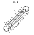
- Fig. 2 is an exploded view in perspective showing one rod element 1.
- the rod element 1 consists of a pair of half portions 1a of identical construction coupled in face to face relation. These half portions 1a are fixed together by bolts 3 as a fastener (see Fig. 1).
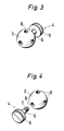
- Fig. 3 is perspective view showing a connecting element 2 and a bolt 4 threadedly engaged therewith.
- Fig. 4 is a perspective view showing the connecting element 2 and the bolt 4 as they appear when separated from each other.
- the bolt 4 has a disk-shaped head 5 and a shank 6 fixed at its base to the head 5.
- the shank 6 is provided with an external thread 7 at its front end.
- the connecting element 2 has a plurality of internal threads 8 formed therein. One of the internal threads 8 is engaged by the external thread 7.
- Fig. 5 is a front view of the connecting element 2.
- a total of six internal threads are formed in the connecting element 2, and the axes of these internal threads 8 are either on straight lines or perpendicular to one another.
- Fig. 6 is side view of the bolt 4 and Fig. 7 is a plan view thereof.
- An outer peripheral edge 10 of the external thread 7 formed on the front end portion of the shank 6 is tapered and truncated-cone shaped, which prevents possible injury during the handling of the kit and facilitates screwing the external screw 7 into one of the internal threads 8.
- Fig. 8 is a plan view showing a half portion 1a of a rod element 1.
- Fig. 9 is a side view of the half portion 1a.
- Fig. 10 is a bottom view thereof.
- Fig. 11 is a section taken along the line XI-XI in Fig. 10.
- the half portion 1a has an outer periphery of a semi-arcuate configuration, and at both ends thereof in the longitudinal direction there are formed taperedly curved portions 11.
- a first recessed portions 17 are defined by a peripheral wall 14, an axially inwardly located walls 15a and 15b, and an axially outwardly located walls 16, of the half portion 1a.
- the first recessed portions 17 are coaxial with the rod element 1, and are configured semi-arcuate, being of uniform radius in the axial direction.
- Second recessed portions 18, 19, each having a smaller diameter than the first recessed portions 17, are respectively formed in the walls 16 and an end walls 12.
- the head 5 of the bolt 4 closely fits in the first recessed portion 17. With the head 5 so held in position, the shank 6 of the bolt 4 fits in the second recessed portions 18, 19.
- the axes of the second recessed portions are coincident with the axis of the rod element 1.
- a barrel portion 21 having an internal thread 20 formed therein is provided axially inwardly of one wall 15a of the half portion 1a.
- An upwardly protruding annular ledge 22 is formed on the end of the barrel portion 21.
- Walls 23, 24, 25, 26 and an axially extending wall 27 are formed in the half portion 1a.
- a positioning recess 28 is formed at an intersection between the walls 25 and 27.
- a barrel portion 30 defining a through hole 29 is provided axially inwardly of the other wall 15b of the half portion 1a.
- a notch 32 corresponding to the annular ledge 22 is formed on the end of the barrel portion 30 defining the through-hole 29.
- the protrusion 31 corresponds to the recess 28.
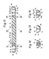
- Fig. 12 is a section taken along the line XII-XII in Fig. 11.
- the spiral ridges of the internal thread formed in the barrel 21 ha a comparatively large width in the axial direction of the thread 20 (in the vertical direction in Fig. 12), which fact contributes toward improved strength and reduced number of turns required in screwing the bolt 3 and facilitates assembling and disassembling.
- Fig. 13 is a section taken along the line XIII-XIII in Fig. 11.
- the walls 25, 27 continue to the peripheral wall 14, which fact contributes toward increased strength of the half portion 1a, and accordingly of the rod element 1.
- Fig. 14 is a section taken along the line XIV-XIV in Fig. 11.
- a recess 33 is formed in a connecting zone between the barrel portion 30 and the peripheral wall 14.
- the head 34 of the bolt 3 shown in Fig. 1 fits into the recess 33.
- the external thread 36 formed on the shank 35 of the bolt 3 engages the internal thread 20 of the other half portion 1a.
- Fig. 15 is a plan view showing a pair of half portions 1a coupled together by bolt 3.
- Fig. 16 is a side view thereof.
- Fig. 17 is a right end view in side elevation showing the coupled configuration in Figs. 15 and 16.
- the external thread formed on the shank 35 of the bolt 3 extends through the through-hole 29 of one half portion 1a and engages the internal thread 20 of the other half portion 1a. With the shank 35 held in that position, the head 34 of the bolt 3 never does protrude radially outwardly of the outer periphery of the half portion 1a.
- the head 34 of the bolt 3 seats on the bottom 33a of the recess 33.
- a cross-shaped arcuate depression 34a is formed on the bolt head 34. Therefore, the bolt 3 can be tightened or unscrewed with a coin.
- a slight notch 37 is formed on both longitudinal side edges of the half portion 1a. The presence of such notch 37 prevents possible injury during manual handling of the half portions 1a. No notch 37 is present on the curved portion 11 at either end of the half portion 1a.
- the peripheral surface of the end wall 12 of the half portion 1a forms an arcuate surface 38 running along the outer periphery of the connecting element 2.
- the arcuate surface 38 may be brought into closed surface contact with the outer periphery of the connecting element 2, which fact ensures firm connection between the rod element 1 and the connecting element 2 and prevents loose connection.
- each half portion 1a is configured generally symmetrically relative to a symmetrical plane perpendicular to kits axis at a median location thereof, and the internal thread 20 and the through-hole 29 are equispaced from the symmetrical plane 39, the recess 28 and protrusion 31 being also equispaced from the symmetrical plane 39.
- each rod element 1 is comprised of a pair of half portions 1a having an identical configuration, which fact means simplified construction and reduced number of parts. Furthermore this means that only one set of mold is required in the fabrication of such rod element, which in turn means improved productivity.
- Fig. 18 is a side view showing a bolt 3.
- Fig. 19 is a front view of the bolt 3.
- the outer periphery 40 of head 34 of the bolt 3 is spherical.
- the front end outer peripheral edge 41 of the external thread 36 is of a tapered truncated cone shape, which fact ensures easy engagement of the external thread 36 with the internal thread 20 and eliminate the possibility of any personal injury being caused during the handling of the kit, thus assuring handling safety.
- Fig. 20 is a perspective view showing an assembly 43 constructed by using such rod elements 1, bolts 3, 4, and connecting elements 2 in plurality as shown in Figs. 1 to 19.
- assembly 43 is constructed, it is very easy to construct an assembly 44 shown in Fig. 21, according to the invention.
- bolts 4 may be removed from connecting elements 46, 47 by rotating the bolts by finger.
- Bolts 4 are brought in thread engagement with connecting elements 48, 49 of the assembly 43, and then rod elements 50, 51 for the assembly 44 in Fig. 21 are fixed in position.
- Fig. 22 is a perspective view showing another form of assembly according to the invention.
- plate elements 53 are used.
- each plate element 53 has support pieces 54, which engage inner side periphery of rod elements 55 of the assembly as Fig. 24 shows.
- Rod elements 45, 50 51, 55 have a configuration similar to that of aforesaid rod element 1, and connecting elements 46, 47, 48, 49 have a configuration similar to that of the connecting element 2.
- the axis of the internal threads 8 in each connecting body 2 are either on same straight line or perpendicular to one another, but alternatively they may have such other angles as 35° and 45°. It is also possible that connecting elements 2 having different angles for the axes of the internal threads are differentiated in color from one another. Such differentiation may enable younger children to easily construct an assembly in accordance with the invention. Further, differentiating bolt elements in color from bolts 3 add to the beauty of the assembly kit. Differentiating each pair of half portions 1a constituting a rod element 1 in color from one to the other will also add to the beauty of the kit.
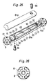
- Fig. 25 is an exploded view in perspective showing another embodiment of the invention.
- Fig. 26 is a plan view of a connecting element 61.
- Fig. 27 is a plan view of a bolt 64.
- Fig. 28 is a longitudinal section of the bolt 64 shown in Fig. 27.
- Fig. 29 is a plan view of a bolt 65.
- Fig. 30 is a longitudinal sectional view showing the bolt 65 shown in Fig. 29.
- This embodiment is similar to the earlier described embodiment, with comparable portions given identical reference numerals.
- the connecting element 61 has a configuration more convenient for molding purposes than the connecting element 2 in the earlier mentioned embodiment.
- a protrusion 62 formed on the wall 25 of a half portion 81a extends perpendicularly to the axis of the half portion 81a and is generally of a rectangular parallelepiped configuration, its both ends in the longitudinal direction being chamfered.
- the wall 26 has recess 63 formed therein correspondingly to the protrusion 62.
- the protrusion 62 and the recess 63 are larger in size than the protrusion 31 and the recess 28 in the earlier embodiment. This ensures more accurate positioning and fitting in assembling a pair of half portions 81a.
- Bolts 64, 65 have fitting holes 66, 67 respectively formed therein which extend therethrough in the axial direction thereof.
- An axially perpendicular section of the fitting holes 66, 67 each is square.
- a clamping device 70 shown in Figs. 31 to 33 has a fitting portion 71 formed in a square rod shape, which fits in the fitting holes 66, 67. By holding and turning a handle portion 72 continued to the fitting portion 71 is it possible to clamp the bolts 64, 65 easily.
- Heads 64a, 65a of the bolts 64, 65 have depressions 64b, 65b formed thereon as in the case of the bolt 3 in the earlier mentioned embodiment, so that the bolts 64, 65 may be readily clamped by using a coin.
- fitting holes 66, 67 extend through the entire axial length of the bolts 64, 65 from the heads 64a, 65a to the front ends 64e, 65e of shanks 64d, 65d having external threads 64c, 65c formed thereon, and this prevents the possibility of windpipe choking in the event of accidental swallowing by an infant and thus assures improved safety.
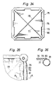
- Fig. 34 is a bottom view of a plate element 75.
- Fig. 35 is a plan view showing the plate element 75 as it appears when fixed to a rod member 81.
- Fig. 36 is a section taken along the line A-A in Fig. 35.
- Mutually intersecting two reinforcement ribs 77, 78 are formed on the back of a sheet portion 76 of the plate element 75.
- a peripheral edge portion 80 having support pieces 79 formed thereon is provided around outer periphery of the sheet portion 76.
- the plate element 75 formed in this way is more durable than the plate element 53 in earlier embodiment, because it is reinforced, and is easy to remove.
- Support pieces 79 are formed in pair on each side, and therefore they are not likely to slippage in the event of external force being exerted in a direction perpendicular to the thicknesswise direction of the plate member 75 (in the direction parallel to the sheet surface of Fig. 34).
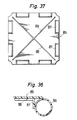
- Fig. 37 is a bottom view of another form of a plate element 85 corresponding to Fig. 34 in accordance with another embodiment of the invention and Fig. 38 is a section showing the plate element 85 when fixed to a rod member 86.
- Support pieces 87 are fixed to the rod element 86 in the condition affixed to outer surface of the rod element 86.
- Rib plate 88, 89 are mounted on the sheet portion 85.
- the assembly kit in accordance with the invention may be formed of synthetic resins.
- assembly kit according to the invention may be used as a toy, but also it may be worked in connection with shelves or the like.
- the assembly kit according to the invention may be very widely in general households.
Landscapes
- Engineering & Computer Science (AREA)
- General Engineering & Computer Science (AREA)
- Mechanical Engineering (AREA)
- Architecture (AREA)
- Physics & Mathematics (AREA)
- Electromagnetism (AREA)
- Civil Engineering (AREA)
- Structural Engineering (AREA)
- Toys (AREA)
Applications Claiming Priority (2)
| Application Number | Priority Date | Filing Date | Title |
|---|---|---|---|
| JP227504/85 | 1985-10-12 | ||
| JP60227504A JPS6287181A (ja) | 1985-10-12 | 1985-10-12 | 玩具などの組立体 |
Publications (2)
| Publication Number | Publication Date |
|---|---|
| EP0219148A1 true EP0219148A1 (fr) | 1987-04-22 |
| EP0219148B1 EP0219148B1 (fr) | 1990-02-07 |
Family
ID=16861928
Family Applications (1)
| Application Number | Title | Priority Date | Filing Date |
|---|---|---|---|
| EP86201516A Expired - Lifetime EP0219148B1 (fr) | 1985-10-12 | 1986-09-02 | Trousse d'assemblage pour jouet ou similaire |
Country Status (6)
| Country | Link |
|---|---|
| US (1) | US4781644A (fr) |
| EP (1) | EP0219148B1 (fr) |
| JP (1) | JPS6287181A (fr) |
| KR (1) | KR870003809A (fr) |
| AU (1) | AU588050B2 (fr) |
| DE (1) | DE3668787D1 (fr) |
Cited By (1)
| Publication number | Priority date | Publication date | Assignee | Title |
|---|---|---|---|---|
| USD916186S1 (en) * | 2018-10-23 | 2021-04-13 | Spiring Enterprises Limited | Model of a molecular bond |
Families Citing this family (28)
| Publication number | Priority date | Publication date | Assignee | Title |
|---|---|---|---|---|
| US4998023A (en) * | 1989-06-22 | 1991-03-05 | Lakeside Manufacturing, Inc. | Portable utility cart |
| DK168194B1 (da) * | 1991-11-06 | 1994-02-28 | Lego As | En skrue til et legetøjsbyggesæt |
| CN2177514Y (zh) * | 1994-01-03 | 1994-09-21 | 佛山市叶泰玩具厂有限公司 | 插接组合玩具 |
| US5769442A (en) * | 1994-01-31 | 1998-06-23 | Teksource, Hlc | Structural shell frames and method of making same |
| US5944439A (en) * | 1996-01-29 | 1999-08-31 | Safco Products Co. | Metal shelving connector and kit |
| KR200179314Y1 (ko) * | 1999-11-11 | 2000-04-15 | 박영욱 | 블럭완구 |
| US6491563B1 (en) * | 2000-04-24 | 2002-12-10 | Scott Bailey | Ball and socket construction toy |
| KR100343562B1 (ko) * | 2000-05-09 | 2002-07-20 | 김세곤 | 풍선 장식용 골조 |
| US6688068B2 (en) * | 2002-02-28 | 2004-02-10 | Honeywell | Reconfigurable erectable truss structure |
| US6651826B1 (en) * | 2002-05-31 | 2003-11-25 | Ahimsa Studios, Inc. | Interlocking pipe storage system |
| ITRM20040362A1 (it) * | 2004-07-19 | 2004-10-19 | Edoardo Tusacciu | Sistema per la realizzazione di costruzioni complesse. |
| US20060084357A1 (en) * | 2004-10-15 | 2006-04-20 | Rosen Lawrence I | Illuminated toy construction kit |
| JP4720183B2 (ja) * | 2005-01-06 | 2011-07-13 | 東京電力株式会社 | 超音波流量計測装置およびその流量計測方法 |
| JP4720192B2 (ja) * | 2005-01-24 | 2011-07-13 | 東京電力株式会社 | 超音波流量計測方法 |
| US20080016789A1 (en) * | 2006-07-18 | 2008-01-24 | Boots Alfred H | Spherical hub for modular structure system |
| US7785170B2 (en) * | 2007-07-10 | 2010-08-31 | Chernick Mark J | Novelty device having elastomeric protrusions with hard plastic terminations and its associated method of construction |
| WO2011031829A2 (fr) * | 2009-09-09 | 2011-03-17 | Rhino Toys, Inc. | Jouet manuel |
| WO2012001452A1 (fr) * | 2010-07-01 | 2012-01-05 | Didier Bernardin | Ensemble de construction pour structure spatiale avec vis mobile |
| EP2588765A1 (fr) * | 2010-07-01 | 2013-05-08 | Asinvent Limited | Ensemble de construction pour structure spatiale avec arbre d'entraînement |
| BE1019854A3 (nl) * | 2011-02-28 | 2013-01-08 | Vandoren Rolf | Constructiespeelgoed. |
| USD708400S1 (en) * | 2012-07-03 | 2014-07-01 | Woodstream Corporation | Hummingbird feeder |
| CN107530566A (zh) * | 2015-02-16 | 2018-01-02 | 吉拉提家族投资私人有限公司 | 模块化游乐场设备 |
| KR101808964B1 (ko) * | 2016-12-05 | 2017-12-22 | 박수진 | 교육용 조립교구 |
| USD902321S1 (en) * | 2019-01-29 | 2020-11-17 | Gymworld Inc. | Toy block |
| EP3935431A4 (fr) * | 2019-03-06 | 2022-11-02 | Afshari, Ali, Reza | Système de cage optique |
| USD892945S1 (en) * | 2020-03-18 | 2020-08-11 | Daniel Patterson | Building toy |
| EP4213956A1 (fr) * | 2020-09-16 | 2023-07-26 | Verster, Abraham Marthinus | Kit de construction |
| USD982095S1 (en) * | 2020-12-18 | 2023-03-28 | Lego A/S | Element for a toy building set |
Citations (3)
| Publication number | Priority date | Publication date | Assignee | Title |
|---|---|---|---|---|
| FR1007327A (fr) * | 1949-12-17 | 1952-05-05 | Jeu de construction à billes formant rotules | |
| EP0044057A1 (fr) * | 1980-07-15 | 1982-01-20 | MERO-Raumstruktur GmbH & Co. | Noeud de liaison pour éléments longitudinaux en bois de treillis, en particulier treillis tridimensionnaux |
| WO1983002633A1 (fr) * | 1982-02-01 | 1983-08-04 | Angus John Duncan Brown | Connecteur pour barres tubulaires et organes de fixation dans une ossature tridimensionnelle |
Family Cites Families (4)
| Publication number | Priority date | Publication date | Assignee | Title |
|---|---|---|---|---|
| SU715735A1 (ru) * | 1975-04-08 | 1980-02-15 | Узбекское Отделение Ордена Трудового Красного Знамени Центрального Научно- Исследовательского И Проектного Института Строительных Металлоконструкций Цниипроектстальконструкция | Узловое соединение элементов пространственного каркаса |
| US4129975A (en) * | 1977-03-09 | 1978-12-19 | Matrix Toys, Inc. | Construction set having clip fasteners |
| DE7820267U1 (de) * | 1978-07-06 | 1979-02-15 | Ruether, Hubert, Dipl.-Ing., 2105 Seevetal | Steckverbinder mit Verbindungsrohr und einer gesicherten, lösbaren Steckverbindung beider |
| US4313687A (en) * | 1978-09-05 | 1982-02-02 | Juan Martinez Apeztegui | Prefabricated spatial structure |
-
1985
- 1985-10-12 JP JP60227504A patent/JPS6287181A/ja active Granted
-
1986
- 1986-08-21 US US06/898,586 patent/US4781644A/en not_active Expired - Fee Related
- 1986-08-25 AU AU61797/86A patent/AU588050B2/en not_active Ceased
- 1986-08-29 KR KR1019860007187A patent/KR870003809A/ko not_active Withdrawn
- 1986-09-02 DE DE8686201516T patent/DE3668787D1/de not_active Expired - Fee Related
- 1986-09-02 EP EP86201516A patent/EP0219148B1/fr not_active Expired - Lifetime
Patent Citations (3)
| Publication number | Priority date | Publication date | Assignee | Title |
|---|---|---|---|---|
| FR1007327A (fr) * | 1949-12-17 | 1952-05-05 | Jeu de construction à billes formant rotules | |
| EP0044057A1 (fr) * | 1980-07-15 | 1982-01-20 | MERO-Raumstruktur GmbH & Co. | Noeud de liaison pour éléments longitudinaux en bois de treillis, en particulier treillis tridimensionnaux |
| WO1983002633A1 (fr) * | 1982-02-01 | 1983-08-04 | Angus John Duncan Brown | Connecteur pour barres tubulaires et organes de fixation dans une ossature tridimensionnelle |
Cited By (1)
| Publication number | Priority date | Publication date | Assignee | Title |
|---|---|---|---|---|
| USD916186S1 (en) * | 2018-10-23 | 2021-04-13 | Spiring Enterprises Limited | Model of a molecular bond |
Also Published As
| Publication number | Publication date |
|---|---|
| DE3668787D1 (de) | 1990-03-15 |
| AU588050B2 (en) | 1989-09-07 |
| AU6179786A (en) | 1987-04-16 |
| EP0219148B1 (fr) | 1990-02-07 |
| JPS6287181A (ja) | 1987-04-21 |
| KR870003809A (ko) | 1987-05-04 |
| JPH0365196B2 (fr) | 1991-10-09 |
| US4781644A (en) | 1988-11-01 |
Similar Documents
| Publication | Publication Date | Title |
|---|---|---|
| EP0219148A1 (fr) | Trousse d'assemblage pour jouet ou similaire | |
| US6836935B2 (en) | Adjustable magnetic snap fastener | |
| EP0125824B1 (fr) | Elément de construction démontable | |
| US3927489A (en) | Ring elements, channel elements, and connectors for joining same | |
| US5611187A (en) | Construction system | |
| US5269230A (en) | Joint-and-beam platform | |
| JPS62192805U (fr) | ||
| US4446605A (en) | Clamp | |
| JPH0387206U (fr) | ||
| JPS62110190U (fr) | ||
| JPH10315159A (ja) | 工具の継ぎ柄 | |
| JPH0287194U (fr) | ||
| JPH0341219U (fr) | ||
| JPH031015Y2 (fr) | ||
| CN2371386Y (zh) | 一种套管式连接紧固装置 | |
| JPS6334902Y2 (fr) | ||
| JPH02130952U (fr) | ||
| JPS634270U (fr) | ||
| JPH0231708U (fr) | ||
| TWM651825U (zh) | 砂輪片拆裝工具 | |
| JPH0244893Y2 (fr) | ||
| JPH0333207U (fr) | ||
| JPS63138359U (fr) | ||
| JPH0234651U (fr) | ||
| JPS61200923U (fr) |
Legal Events
| Date | Code | Title | Description |
|---|---|---|---|
| PUAI | Public reference made under article 153(3) epc to a published international application that has entered the european phase |
Free format text: ORIGINAL CODE: 0009012 |
|
| AK | Designated contracting states |
Kind code of ref document: A1 Designated state(s): DE FR GB NL |
|
| 17P | Request for examination filed |
Effective date: 19871021 |
|
| 17Q | First examination report despatched |
Effective date: 19880530 |
|
| GRAA | (expected) grant |
Free format text: ORIGINAL CODE: 0009210 |
|
| AK | Designated contracting states |
Kind code of ref document: B1 Designated state(s): DE FR GB NL |
|
| REF | Corresponds to: |
Ref document number: 3668787 Country of ref document: DE Date of ref document: 19900315 |
|
| ET | Fr: translation filed | ||
| PGFP | Annual fee paid to national office [announced via postgrant information from national office to epo] |
Ref country code: GB Payment date: 19900821 Year of fee payment: 5 |
|
| PLBE | No opposition filed within time limit |
Free format text: ORIGINAL CODE: 0009261 |
|
| STAA | Information on the status of an ep patent application or granted ep patent |
Free format text: STATUS: NO OPPOSITION FILED WITHIN TIME LIMIT |
|
| 26N | No opposition filed | ||
| PG25 | Lapsed in a contracting state [announced via postgrant information from national office to epo] |
Ref country code: NL Effective date: 19910401 |
|
| NLV4 | Nl: lapsed or anulled due to non-payment of the annual fee | ||
| PG25 | Lapsed in a contracting state [announced via postgrant information from national office to epo] |
Ref country code: FR Effective date: 19910530 |
|
| PG25 | Lapsed in a contracting state [announced via postgrant information from national office to epo] |
Ref country code: DE Effective date: 19910601 |
|
| REG | Reference to a national code |
Ref country code: FR Ref legal event code: ST |
|
| PG25 | Lapsed in a contracting state [announced via postgrant information from national office to epo] |
Ref country code: GB Effective date: 19910902 |
|
| GBPC | Gb: european patent ceased through non-payment of renewal fee |