EP0219149A1 - System zur Bestimmung des Drucks zwischen zwei Walzen - Google Patents
System zur Bestimmung des Drucks zwischen zwei Walzen Download PDFInfo
- Publication number
- EP0219149A1 EP0219149A1 EP86201528A EP86201528A EP0219149A1 EP 0219149 A1 EP0219149 A1 EP 0219149A1 EP 86201528 A EP86201528 A EP 86201528A EP 86201528 A EP86201528 A EP 86201528A EP 0219149 A1 EP0219149 A1 EP 0219149A1
- Authority
- EP
- European Patent Office
- Prior art keywords
- layer
- conducting material
- electrically conducting
- sensor
- regions
- Prior art date
- Legal status (The legal status is an assumption and is not a legal conclusion. Google has not performed a legal analysis and makes no representation as to the accuracy of the status listed.)
- Granted
Links
- 239000004020 conductor Substances 0.000 claims abstract description 35
- 229920002981 polyvinylidene fluoride Polymers 0.000 claims abstract description 20
- 239000002033 PVDF binder Substances 0.000 claims abstract description 19
- 239000000463 material Substances 0.000 claims abstract description 15
- 239000003989 dielectric material Substances 0.000 claims abstract description 6
- 238000000034 method Methods 0.000 claims description 19
- 238000005253 cladding Methods 0.000 claims description 15
- 230000005540 biological transmission Effects 0.000 claims description 12
- 229920002379 silicone rubber Polymers 0.000 claims description 8
- 239000004945 silicone rubber Substances 0.000 claims description 8
- 230000005684 electric field Effects 0.000 claims description 7
- RYGMFSIKBFXOCR-UHFFFAOYSA-N Copper Chemical compound [Cu] RYGMFSIKBFXOCR-UHFFFAOYSA-N 0.000 claims description 4
- 239000010949 copper Substances 0.000 claims description 4
- 229910052802 copper Inorganic materials 0.000 claims description 4
- 238000013016 damping Methods 0.000 claims description 4
- 238000004519 manufacturing process Methods 0.000 claims description 4
- 239000000853 adhesive Substances 0.000 claims description 3
- 230000001070 adhesive effect Effects 0.000 claims description 3
- 239000004411 aluminium Substances 0.000 claims description 2
- XAGFODPZIPBFFR-UHFFFAOYSA-N aluminium Chemical compound [Al] XAGFODPZIPBFFR-UHFFFAOYSA-N 0.000 claims description 2
- 229910052782 aluminium Inorganic materials 0.000 claims description 2
- 238000005530 etching Methods 0.000 claims description 2
- 238000007759 kiss coating Methods 0.000 claims description 2
- 238000004544 sputter deposition Methods 0.000 claims 1
- 238000001771 vacuum deposition Methods 0.000 claims 1
- 239000010410 layer Substances 0.000 description 68
- 239000012790 adhesive layer Substances 0.000 description 3
- 239000012858 resilient material Substances 0.000 description 3
- 230000000712 assembly Effects 0.000 description 2
- 238000000429 assembly Methods 0.000 description 2
- 238000006243 chemical reaction Methods 0.000 description 2
- 230000006835 compression Effects 0.000 description 2
- 238000007906 compression Methods 0.000 description 2
- 238000009826 distribution Methods 0.000 description 2
- 229920001971 elastomer Polymers 0.000 description 2
- BQCIDUSAKPWEOX-UHFFFAOYSA-N 1,1-Difluoroethene Chemical compound FC(F)=C BQCIDUSAKPWEOX-UHFFFAOYSA-N 0.000 description 1
- 230000003213 activating effect Effects 0.000 description 1
- 230000008878 coupling Effects 0.000 description 1
- 238000010168 coupling process Methods 0.000 description 1
- 238000005859 coupling reaction Methods 0.000 description 1
- 238000006073 displacement reaction Methods 0.000 description 1
- 125000001153 fluoro group Chemical group F* 0.000 description 1
- -1 for example Substances 0.000 description 1
- 125000004435 hydrogen atom Chemical group [H]* 0.000 description 1
- 230000002452 interceptive effect Effects 0.000 description 1
- 238000012216 screening Methods 0.000 description 1
- 229920006126 semicrystalline polymer Polymers 0.000 description 1
Images

Classifications
-
- B—PERFORMING OPERATIONS; TRANSPORTING
- B41—PRINTING; LINING MACHINES; TYPEWRITERS; STAMPS
- B41F—PRINTING MACHINES OR PRESSES
- B41F33/00—Indicating, counting, warning, control or safety devices
- B41F33/0072—Devices for measuring the pressure between cylinders or bearer rings
-
- G—PHYSICS
- G01—MEASURING; TESTING
- G01B—MEASURING LENGTH, THICKNESS OR SIMILAR LINEAR DIMENSIONS; MEASURING ANGLES; MEASURING AREAS; MEASURING IRREGULARITIES OF SURFACES OR CONTOURS
- G01B17/00—Measuring arrangements characterised by the use of infrasonic, sonic or ultrasonic vibrations
- G01B17/02—Measuring arrangements characterised by the use of infrasonic, sonic or ultrasonic vibrations for measuring thickness
- G01B17/025—Measuring arrangements characterised by the use of infrasonic, sonic or ultrasonic vibrations for measuring thickness for measuring thickness of coating
-
- G—PHYSICS
- G01—MEASURING; TESTING
- G01L—MEASURING FORCE, STRESS, TORQUE, WORK, MECHANICAL POWER, MECHANICAL EFFICIENCY, OR FLUID PRESSURE
- G01L1/00—Measuring force or stress, in general
- G01L1/16—Measuring force or stress, in general using properties of piezoelectric devices
-
- G—PHYSICS
- G01—MEASURING; TESTING
- G01L—MEASURING FORCE, STRESS, TORQUE, WORK, MECHANICAL POWER, MECHANICAL EFFICIENCY, OR FLUID PRESSURE
- G01L1/00—Measuring force or stress, in general
- G01L1/25—Measuring force or stress, in general using wave or particle radiation, e.g. X-rays, microwaves, neutrons
- G01L1/255—Measuring force or stress, in general using wave or particle radiation, e.g. X-rays, microwaves, neutrons using acoustic waves, or acoustic emission
-
- G—PHYSICS
- G01—MEASURING; TESTING
- G01L—MEASURING FORCE, STRESS, TORQUE, WORK, MECHANICAL POWER, MECHANICAL EFFICIENCY, OR FLUID PRESSURE
- G01L5/00—Apparatus for, or methods of, measuring force, work, mechanical power, or torque, specially adapted for specific purposes
- G01L5/0061—Force sensors associated with industrial machines or actuators
- G01L5/0076—Force sensors associated with manufacturing machines
- G01L5/0085—Force sensors adapted for insertion between cooperating machine elements, e.g. for measuring the nip force between rollers
-
- Y—GENERAL TAGGING OF NEW TECHNOLOGICAL DEVELOPMENTS; GENERAL TAGGING OF CROSS-SECTIONAL TECHNOLOGIES SPANNING OVER SEVERAL SECTIONS OF THE IPC; TECHNICAL SUBJECTS COVERED BY FORMER USPC CROSS-REFERENCE ART COLLECTIONS [XRACs] AND DIGESTS
- Y10—TECHNICAL SUBJECTS COVERED BY FORMER USPC
- Y10S—TECHNICAL SUBJECTS COVERED BY FORMER USPC CROSS-REFERENCE ART COLLECTIONS [XRACs] AND DIGESTS
- Y10S310/00—Electrical generator or motor structure
- Y10S310/80—Piezoelectric polymers, e.g. PVDF
Definitions
- the invention relates to a system for determining the pressure which is exerted on an object which is passed between two rollers, at least one of which is provided with a relatively hard core having a resilient cladding.
- the invention further relates to a method for the manufacture of a sensor for use in the previously mentioned system and also relates to the sensor itself.
- rollers In devices in which paper, films or other relatively thin sheet-like materials are conveyed, such as in printing presses, copying machines and the like, use is frequently made of combinations of rollers pressed against each other between which the paper, film and the like are passed.
- at least one of the rollers is provided with a resilient outer layer, for example of rubber.
- the invention therefore provides a system for determining the pressure which is exerted on an object which is passed between two rollers, at least one of which is provided with a relatively hard core having a resilient cladding, characterised by
- the layer of polyvinylidene fluoride has piezoelectric properties.
- an electrical pulse is presented to selected detector regions, as a result of which, because of the piezoelectric properties of the polyvinylidene fluoride layer, a vibration is generated in said layer resulting in the emission of an ultrasonic energy pulse.
- This pulse is coupled into the resilient cladding of the roller on the side of the first layer of electrically conducting material. After propagation through said cladding, the pulse is reflected against the relatively hard roller core, passes back through the cladding and reaches the sensor film, where an electric field which can be detected by the receiving device is generated in the polyvinylidene fluoride layer.
- a fundamentally important component of the system according to the invention is formed by the sensor which is used in the system.
- the invention is therefore directed not only at the system as a whole but also at the sensor which can be used in said system.
- said sensor consists of a laminated film, the thickness of which corresponds at least approximately to the objects to be conveyed between the rollers, the length of which is maximally equal to the length of the nip between the rollers to be examined and the width of which is sufficient for it to be possible to realise the lines to the transmission/receiving device, which film comprises in sequence - a first layer of electrically conducting material, - a layer of polyvinylidene fluoride, - a second layer of electrically conducting material, in which layer one or more detector regions are present which make no electrical contact with the part of the layer situated around them, which detector regions consist of first elongated regions which are in line at a pretermined mutual distance and of conductor regions which run approximately essentially perpendicular thereto and which lead to connection regions, - a layer of dielectrically conducting material, - a third layer of electrically conducting material.
- the invention further relates to methods for the manufacture of laminated films which can be used as sensor film in the system according to the invention.
- Figure 1 shows a section through a part of a laminated film.
- the film is constructed of a first layer 10 of electrically conducting material, which layer is situated on a layer 11 of polyvinylidene fluoride.
- Said layer 22 is attached via an adhesive layer 15 to a second layer 12 of electrically conducting material.
- Said layer 12 is situated on a layer 13 of dielectric material, the other surface of which is covered by a third layer 14 of electrically conducting material.
- a further layer 16 of flexible material such as silicone rubber.
- Figure 2 shows a plan view of the layer 12 of electrically conducting material.
- This layer is provided with a number of detector regions which each consist of an elongated region 20 and a conductor region 21 adjoining approximately perpendicular thereto which is connected at its other end to the connection region 22.
- Each of these essentially T-shaped detector regions is separated by a small gap from the remaining part of the layer 12.
- All the elongated regions 20 lie in a line on a strip of the layer 12, which strip is gripped between the rollers during the use of the film.
- the operation of the sensor is based on the properties of the layer 11 of polyvinylidene fluoride and said properties will be discussed below.
- Polyvinylidene fluoride is a semi-crystalline polymer.
- the material is readily manufactured in the forms of a film and has, in addition to crystalline properties, also amorphous properties such as flexibility and unbreakability.
- the film consists of C chains with H and F branches. The H and F atoms provide a dipole moment. These dipoles can be aligned at elevated temperature (approx. 70°C) by stretching the film and applying an electric field. If said dipoles are aligned and subsequently "frozen-in", then the film exhibits piezoelectric properties. The internal dipoles are compensated for at the surface of the film.
- the film is now compressed in the thickness direction as a result of an external pressure, then the internal dipoles will become less oriented and the dipole moment will decrease because the lattice distances are compressed. The result is that the compensation charge has to be removed and this can be detected externally.
- the layer 11 of polyvinylidene fluoride with the first electrically conducting layer 10 at the top and the second electrically conducting layer 12 at the bottom is in fact used for the piezoelectric conversion.
- the layer 10 is earthed.
- the connection regions of the detector regions of the layer 12 are connected to suitable measuring instruments and the remaining part of the layer 12 is earthed. If a pressure is then exerted on the film, as a result of which the film is deformed in the thickness direction locally, in particular at the position of the elongated regions 20 of the detector regions, then this mechanical deformation will bring about an electric charge displacement which can be detected via the measuring instruments connected to the detector regions.
- the ultrasonic vibration emitted towards the bottom in Figure 1 is damped by the further layers of the film assembly present there.
- the layers 12, 13, 14 acoustic energy is virtually completely absorbed. If the layers 12, 14 are manufactured from copper and if the layer 13 is manufactured from capton, then only 1% of the signal generated in the layer 11 is transmitted.
- a further consequence of this damping at the bottom of said film assembly is that the mechanical vibration in the layer 11 decays very rapidly after termination of the activating electric field so that the sensor can be switched over rapidly from transmission to receiving.
- the lowermost, third conducting layer 14 is earthed when the film is in use and these layers together form a Faraday cage, as a result of which an effective screening against external interfering effects is obtained.
- the layer 16 at the top is manufactured from a material with a low acoustic impedance, for example silicone rubber, with which a good transmission and a good coupling in of the acoustic vibration into the resilient cladding of the roller are obtained.
- a material with a low acoustic impedance for example silicone rubber
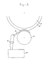
- FIG 3 an arrangement is shown very diagrammatically of two rollers 31 and 32 with a relatively thin sensor 34 between them.
- the roller 31 is provided with a hard inflexible core and an outer layer 33 of resilient material such as, for example, rubber.
- the roller 32 is constructed as a hard roller, but the invention can also be used for two rollers which are both provided with a resilient cladding.
- the sensor 34 is connected to a measuring apparatus 36 via the lines 35.
- the lines 35 include signal lines to each of the connection regions 22 of the sensor and also at least one earth line.
- the measuring apparatus 36 is a device known per se, for example the ultrasonic test apparatus USIP 12 made by Krautkrämer.
- an electric high-frequency pulse is transmitted at a predetermined time instant t0 to the sensor 34, as a result of which, in the manner now already described, an ultrasonic vibration is generated by each of the detector regions in the sensor, which vibration is emitted to the roller 31 in Figure 3.
- the ultrasonic vibration at the bottom, in the direction of the roller 32 is damped in the sensor itself.
- the ultrasonic vibration emitted passes through the resilient cladding 33, is reflected by the hard core of the roller 31 and returns to the sensor 34.
- the returning ultrasonic vibration ensures that in the sensor 34 an electric pulse, which is fed to the measuring apparatus 36, is generated at time instant t1.
- the time difference t1-t0 is determined, which time difference is a measure of the thickness of the resilient cladding 33 in the nip between the rollers 31 and 32.
- the resilient cladding 33 is somewhat deformed by the presence of the sensor 34.
- the sensor illustrated in Figures 2 and 3 may be manufactured by fabricating a first part assembly consisting of a dielectric film to which a layer of electrically conducting material is applied on both sides.
- This first part aasembly then comprises the layers 12, 13 and 14.
- copper is preferably used and for the layer 13 capton is preferably used.
- other conducting materials and other dielectric materials can also be used.
- the pattern of the detector regions in the layer 12 can be manufactured by any method suitable therefor. Preferably, however, use is made of an etching process to remove the narrow strips of material between the detector regions and the remaining part of the layer.
- a second part assembly is manufactured by providing a polyvinylidene fluoride film with an electrically conducting layer on one side. Said second part assembly then comprises the layers 10 and 11 from Figure 1.
- the layer 10 of electrically conducting material is preferably manufactured from aluminium, but may also be manufactured from copper or another electrically conducting material.
- the two part assemblies are then bonded to each other by means of an adhesive layer (15 in Figure 1).
- the adhesive layer consists, for example, of a solution of 5% Union Carbide 49001. This adhesive is applied at room temperature to the PVDF film by means of a so-called kiss coating. The bonding is then brought about under pressure and temperature (60°C).
- the layer 16 of material having a low acoustic damping for example silicone rubber, is applied during the manufacture of the second part assembly or is applied after the two part assemblies are bonded to each other.
- a so-called "air brush” method is preferably used to apply the silicone rubber to the conducting layer 10.
Landscapes
- Physics & Mathematics (AREA)
- General Physics & Mathematics (AREA)
- Chemical & Material Sciences (AREA)
- Analytical Chemistry (AREA)
- Acoustics & Sound (AREA)
- Health & Medical Sciences (AREA)
- Toxicology (AREA)
- Force Measurement Appropriate To Specific Purposes (AREA)
- Controlling Sheets Or Webs (AREA)
- Length Measuring Devices Characterised By Use Of Acoustic Means (AREA)
Applications Claiming Priority (2)
| Application Number | Priority Date | Filing Date | Title |
|---|---|---|---|
| NL8502475A NL8502475A (nl) | 1985-09-11 | 1985-09-11 | Stelsel voor het bepalen van de druk in de kneep tussen twee rollen. |
| NL8502475 | 1985-09-11 |
Publications (2)
| Publication Number | Publication Date |
|---|---|
| EP0219149A1 true EP0219149A1 (de) | 1987-04-22 |
| EP0219149B1 EP0219149B1 (de) | 1990-05-09 |
Family
ID=19846533
Family Applications (1)
| Application Number | Title | Priority Date | Filing Date |
|---|---|---|---|
| EP86201528A Expired EP0219149B1 (de) | 1985-09-11 | 1986-09-05 | System zur Bestimmung des Drucks zwischen zwei Walzen |
Country Status (5)
| Country | Link |
|---|---|
| US (1) | US4744253A (de) |
| EP (1) | EP0219149B1 (de) |
| JP (1) | JPS6262237A (de) |
| DE (1) | DE3671102D1 (de) |
| NL (1) | NL8502475A (de) |
Cited By (9)
| Publication number | Priority date | Publication date | Assignee | Title |
|---|---|---|---|---|
| EP0267737A3 (de) * | 1986-11-08 | 1989-11-29 | Pennwalt Piezo Film Limited | Vorrichtung zur Messung der Festigkeit |
| EP0538221A3 (en) * | 1991-10-14 | 1993-10-27 | Valmet Paper Machinery Inc | Method and device for measurement of the nip force and/or nip pressure in a nip formed by a revolving roll or a band that is used in the manufacture of paper |
| EP0588776A3 (de) * | 1992-09-16 | 1994-04-13 | Valmet Paper Machinery Inc. | Verfahren und Vorrichtung zum Messen der Kraft und/oder des Druckes in einem Spalt gebildet durch eine sich drehende Walze oder durch ein Band bei der Papierherstellung |
| RU2166740C2 (ru) * | 1998-12-17 | 2001-05-10 | Российский Федеральный Ядерный Центр - Всероссийский Научно-Исследовательский Институт Экспериментальной Физики | Способ изготовления контактного датчика в виде слоистой пленки |
| WO2008086894A1 (en) * | 2007-01-17 | 2008-07-24 | Metso Paper, Inc. | Load measuring device, manufacturing method for the device and control method using the device |
| EP1493565A3 (de) * | 2003-07-01 | 2008-08-20 | Koenig & Bauer Aktiengesellschaft | Walze mit integriertem Drucksensor auf der Umfangsoberfläche |
| EP2090872A4 (de) * | 2006-11-13 | 2011-08-24 | Aisin Seiki | Piezoelektrischer sensor und verfahren zu seiner herstellung |
| GB2529484A (en) * | 2014-08-22 | 2016-02-24 | Univ Sheffield | Deriving contact stress or contact loadusing ultrasound data |
| WO2024112988A1 (de) * | 2022-11-30 | 2024-06-06 | NET-Automation GmbH | Vorrichtung zum erfassen der druckkräfte zwischen zwei unter krafteinwirkung aneinander anstellbaren körpern |
Families Citing this family (8)
| Publication number | Priority date | Publication date | Assignee | Title |
|---|---|---|---|---|
| DE3729409A1 (de) * | 1987-09-03 | 1989-03-16 | Nitsche Wolfgang Priv Doz Dr I | Verfahren zur messung von auf beliebig geformten koerpern wirkenden druecken und kraeften |
| US4945772A (en) * | 1988-11-30 | 1990-08-07 | Westvaco Corporation | Method of roll nip load measurement |
| US5209126A (en) * | 1991-01-04 | 1993-05-11 | Bonneville Scientific | Force sensor |
| US5598639A (en) * | 1995-06-07 | 1997-02-04 | Xerox Corporation | Tool for high temperature roll nip measurements |
| US6201938B1 (en) | 1999-06-11 | 2001-03-13 | Xerox Corporation | Roll fusing apparatus including a fusing nip force controlling assembly |
| US7012768B2 (en) | 2000-12-27 | 2006-03-14 | Ntn Corporation | Optical pick-up |
| JP2007229954A (ja) * | 2006-02-27 | 2007-09-13 | Mitsubishi Heavy Ind Ltd | 印刷機械のニップ確認システム、およびプログラム |
| DE102007031057A1 (de) * | 2007-07-04 | 2009-01-08 | Manroland Ag | Elektrete und deren Einsatz in Druckmaschinen |
Citations (6)
| Publication number | Priority date | Publication date | Assignee | Title |
|---|---|---|---|---|
| US3418850A (en) * | 1965-03-11 | 1968-12-31 | Goddin Derek Joseph Harry | Device for measuring the pressure between two surfaces at least one of which is a roll |
| US4016756A (en) * | 1972-06-08 | 1977-04-12 | Beloit Corporation | Nip load sensing device |
| DE2653556A1 (de) * | 1975-12-19 | 1977-06-30 | Kistler Instrumente Ag | Elektrischer kraftaufnehmer fuer fusskraefte |
| FR2351722A1 (fr) * | 1976-05-20 | 1977-12-16 | Sack Gmbh Maschf | Appareil en vue de mesurer l'ecartement entre les cylindres dans les cages de laminoirs a epaisseur reglee |
| EP0091089A2 (de) * | 1982-04-05 | 1983-10-12 | Siemens Aktiengesellschaft | Drucksensor |
| US4499394A (en) * | 1983-10-21 | 1985-02-12 | Koal Jan G | Polymer piezoelectric sensor of animal foot pressure |
Family Cites Families (5)
| Publication number | Priority date | Publication date | Assignee | Title |
|---|---|---|---|---|
| US4183010A (en) * | 1975-12-08 | 1980-01-08 | Gte Sylvania Incorporated | Pressure compensating coaxial line hydrophone and method |
| US4356423A (en) * | 1980-11-28 | 1982-10-26 | Teledyne Industries, Inc., Geotech Division | Pressure sensitive intrusion sensing line |
| JPS6015534A (ja) * | 1983-07-07 | 1985-01-26 | Dainippon Printing Co Ltd | ロ−ル圧測定装置 |
| US4555953A (en) * | 1984-04-16 | 1985-12-03 | Paolo Dario | Composite, multifunctional tactile sensor |
| US4633122A (en) * | 1985-06-18 | 1986-12-30 | Pennwalt Corporation | Means for electrically connecting electrodes on different surfaces of piezoelectric polymeric films |
-
1985
- 1985-09-11 NL NL8502475A patent/NL8502475A/nl not_active Application Discontinuation
-
1986
- 1986-09-04 JP JP61208840A patent/JPS6262237A/ja active Pending
- 1986-09-05 EP EP86201528A patent/EP0219149B1/de not_active Expired
- 1986-09-05 DE DE8686201528T patent/DE3671102D1/de not_active Expired - Lifetime
- 1986-09-11 US US06/905,970 patent/US4744253A/en not_active Expired - Fee Related
Patent Citations (6)
| Publication number | Priority date | Publication date | Assignee | Title |
|---|---|---|---|---|
| US3418850A (en) * | 1965-03-11 | 1968-12-31 | Goddin Derek Joseph Harry | Device for measuring the pressure between two surfaces at least one of which is a roll |
| US4016756A (en) * | 1972-06-08 | 1977-04-12 | Beloit Corporation | Nip load sensing device |
| DE2653556A1 (de) * | 1975-12-19 | 1977-06-30 | Kistler Instrumente Ag | Elektrischer kraftaufnehmer fuer fusskraefte |
| FR2351722A1 (fr) * | 1976-05-20 | 1977-12-16 | Sack Gmbh Maschf | Appareil en vue de mesurer l'ecartement entre les cylindres dans les cages de laminoirs a epaisseur reglee |
| EP0091089A2 (de) * | 1982-04-05 | 1983-10-12 | Siemens Aktiengesellschaft | Drucksensor |
| US4499394A (en) * | 1983-10-21 | 1985-02-12 | Koal Jan G | Polymer piezoelectric sensor of animal foot pressure |
Non-Patent Citations (2)
| Title |
|---|
| ELECTRONIC DESIGN, vol. 31, no. 11, 26th May 1983, page 77e, Rochelle Park, New York, US; R. ALLAN: "Piezo polymer promises low-cost robotic sensors" * |
| PATENTS ABSTRACTS OF JAPAN, vol. 8, no. 211 (P-303)[1648], 26th September 1984; & JP-A-59 94 028 (NIPPON JIDOSHA BUHIN SOGO KENKYUSHO K.K.) 30-05-1984 * |
Cited By (12)
| Publication number | Priority date | Publication date | Assignee | Title |
|---|---|---|---|---|
| EP0267737A3 (de) * | 1986-11-08 | 1989-11-29 | Pennwalt Piezo Film Limited | Vorrichtung zur Messung der Festigkeit |
| EP0538221A3 (en) * | 1991-10-14 | 1993-10-27 | Valmet Paper Machinery Inc | Method and device for measurement of the nip force and/or nip pressure in a nip formed by a revolving roll or a band that is used in the manufacture of paper |
| US5383371A (en) * | 1991-10-14 | 1995-01-24 | Valmet Paper Machinery, Incorporated | Method and device for measurement of the nip force and/or nip pressure in a nip formed by a revolving roll or a band that is used in the manufacture of paper |
| EP0588776A3 (de) * | 1992-09-16 | 1994-04-13 | Valmet Paper Machinery Inc. | Verfahren und Vorrichtung zum Messen der Kraft und/oder des Druckes in einem Spalt gebildet durch eine sich drehende Walze oder durch ein Band bei der Papierherstellung |
| RU2166740C2 (ru) * | 1998-12-17 | 2001-05-10 | Российский Федеральный Ядерный Центр - Всероссийский Научно-Исследовательский Институт Экспериментальной Физики | Способ изготовления контактного датчика в виде слоистой пленки |
| EP1493565A3 (de) * | 2003-07-01 | 2008-08-20 | Koenig & Bauer Aktiengesellschaft | Walze mit integriertem Drucksensor auf der Umfangsoberfläche |
| EP2090872A4 (de) * | 2006-11-13 | 2011-08-24 | Aisin Seiki | Piezoelektrischer sensor und verfahren zu seiner herstellung |
| US8314536B2 (en) | 2006-11-13 | 2012-11-20 | Aisin Seiki Kabushiki Kaisha | Piezoelectric sensor and method for manufacturing the same |
| WO2008086894A1 (en) * | 2007-01-17 | 2008-07-24 | Metso Paper, Inc. | Load measuring device, manufacturing method for the device and control method using the device |
| US8281671B2 (en) | 2007-01-17 | 2012-10-09 | Metso Paper, Inc. | Load measuring device, manufacturing method for the device and control method using the device |
| GB2529484A (en) * | 2014-08-22 | 2016-02-24 | Univ Sheffield | Deriving contact stress or contact loadusing ultrasound data |
| WO2024112988A1 (de) * | 2022-11-30 | 2024-06-06 | NET-Automation GmbH | Vorrichtung zum erfassen der druckkräfte zwischen zwei unter krafteinwirkung aneinander anstellbaren körpern |
Also Published As
| Publication number | Publication date |
|---|---|
| EP0219149B1 (de) | 1990-05-09 |
| NL8502475A (nl) | 1987-04-01 |
| US4744253A (en) | 1988-05-17 |
| JPS6262237A (ja) | 1987-03-18 |
| DE3671102D1 (de) | 1990-06-13 |
Similar Documents
| Publication | Publication Date | Title |
|---|---|---|
| EP0219149B1 (de) | System zur Bestimmung des Drucks zwischen zwei Walzen | |
| Suzuki et al. | A silicon electrostatic ultrasonic transducer | |
| EP0528279B1 (de) | Biegsame piezoelektrische Vorrichtung | |
| JP2502685B2 (ja) | 超音波探触子の製造方法 | |
| CN1777814B (zh) | 定位局部放电的测量装置及其应用 | |
| US5166573A (en) | Ultrasonic contact transducer and array | |
| US6749573B2 (en) | Passive fetal heart monitoring system | |
| Zhang et al. | Thermally stable fluorocarbon ferroelectrets with high piezoelectric coefficient | |
| EP0379229A2 (de) | Ultraschallsonde | |
| EP3037178B1 (de) | Kapazitiver mikrobearbeiteter ultraschallwandler und testobjekterfassungsvorrichtung mit kapazitivem mikrobearbeitetem ultraschallwandler | |
| JP2002084597A (ja) | 超音波変換器アレーとその製造方法 | |
| KR20080001663A (ko) | 플렉시블 인쇄 회로 기판, 초음파 프로브 및 초음파 프로브제조 방법 | |
| JP2782940B2 (ja) | 浮動型磁気ヘッド装置 | |
| JPH0683516B2 (ja) | 超音波探触子およびその製造方法 | |
| EP4197718B1 (de) | Elektrostatischer anziehungsapparat und roboterhand damit | |
| US6651317B2 (en) | Method for producing an electrical ribbon cable | |
| JPH07301587A (ja) | 薄膜強度測定方法 | |
| JPH08159706A (ja) | 間隔センサ | |
| GB2141902A (en) | Composite transducer | |
| JPS60157060A (ja) | トランスデユ−サ | |
| US6321438B1 (en) | Method of applying a matching layer to a transducer | |
| US7836769B2 (en) | Apparatus and method of measuring acoustical energy applied to a substrate | |
| JP3033667B2 (ja) | 部分放電検出用電極 | |
| JP2935514B2 (ja) | 配列型超音波探触子及びその製造方法 | |
| JPH0371822A (ja) | 電磁遮蔽用複合シートの折曲げ方法 |
Legal Events
| Date | Code | Title | Description |
|---|---|---|---|
| PUAI | Public reference made under article 153(3) epc to a published international application that has entered the european phase |
Free format text: ORIGINAL CODE: 0009012 |
|
| AK | Designated contracting states |
Kind code of ref document: A1 Designated state(s): DE FR GB NL |
|
| 17P | Request for examination filed |
Effective date: 19870910 |
|
| 17Q | First examination report despatched |
Effective date: 19880812 |
|
| GRAA | (expected) grant |
Free format text: ORIGINAL CODE: 0009210 |
|
| AK | Designated contracting states |
Kind code of ref document: B1 Designated state(s): DE FR GB NL |
|
| REF | Corresponds to: |
Ref document number: 3671102 Country of ref document: DE Date of ref document: 19900613 |
|
| PGFP | Annual fee paid to national office [announced via postgrant information from national office to epo] |
Ref country code: FR Payment date: 19900806 Year of fee payment: 5 |
|
| PGFP | Annual fee paid to national office [announced via postgrant information from national office to epo] |
Ref country code: GB Payment date: 19900810 Year of fee payment: 5 |
|
| PGFP | Annual fee paid to national office [announced via postgrant information from national office to epo] |
Ref country code: DE Payment date: 19900829 Year of fee payment: 5 |
|
| ET | Fr: translation filed | ||
| PGFP | Annual fee paid to national office [announced via postgrant information from national office to epo] |
Ref country code: NL Payment date: 19900930 Year of fee payment: 5 |
|
| PLBE | No opposition filed within time limit |
Free format text: ORIGINAL CODE: 0009261 |
|
| STAA | Information on the status of an ep patent application or granted ep patent |
Free format text: STATUS: NO OPPOSITION FILED WITHIN TIME LIMIT |
|
| 26N | No opposition filed | ||
| PG25 | Lapsed in a contracting state [announced via postgrant information from national office to epo] |
Ref country code: GB Effective date: 19910905 |
|
| PG25 | Lapsed in a contracting state [announced via postgrant information from national office to epo] |
Ref country code: NL Effective date: 19920401 |
|
| GBPC | Gb: european patent ceased through non-payment of renewal fee | ||
| NLV4 | Nl: lapsed or anulled due to non-payment of the annual fee | ||
| PG25 | Lapsed in a contracting state [announced via postgrant information from national office to epo] |
Ref country code: FR Effective date: 19920529 |
|
| PG25 | Lapsed in a contracting state [announced via postgrant information from national office to epo] |
Ref country code: DE Effective date: 19920602 |
|
| REG | Reference to a national code |
Ref country code: FR Ref legal event code: ST |