EP0219587A1 - Durchlaufdraht-Elektroerosionsmaschine mit Drehdüsenanordnung - Google Patents
Durchlaufdraht-Elektroerosionsmaschine mit Drehdüsenanordnung Download PDFInfo
- Publication number
- EP0219587A1 EP0219587A1 EP85307523A EP85307523A EP0219587A1 EP 0219587 A1 EP0219587 A1 EP 0219587A1 EP 85307523 A EP85307523 A EP 85307523A EP 85307523 A EP85307523 A EP 85307523A EP 0219587 A1 EP0219587 A1 EP 0219587A1
- Authority
- EP
- European Patent Office
- Prior art keywords
- electrode
- workpiece
- machining
- machine defined
- outlet member
- Prior art date
- Legal status (The legal status is an assumption and is not a legal conclusion. Google has not performed a legal analysis and makes no representation as to the accuracy of the status listed.)
- Granted
Links
- 238000003754 machining Methods 0.000 claims abstract description 77
- 239000007788 liquid Substances 0.000 claims abstract description 30
- 230000000712 assembly Effects 0.000 claims abstract description 14
- 238000000429 assembly Methods 0.000 claims abstract description 14
- 239000012530 fluid Substances 0.000 claims description 20
- 238000006073 displacement reaction Methods 0.000 claims description 3
- 230000015572 biosynthetic process Effects 0.000 abstract 1
- 239000000463 material Substances 0.000 description 6
- 230000000875 corresponding effect Effects 0.000 description 4
- 239000004020 conductor Substances 0.000 description 2
- 238000010276 construction Methods 0.000 description 2
- 201000002672 Miura type epiphyseal chondrodysplasia Diseases 0.000 description 1
- 230000000903 blocking effect Effects 0.000 description 1
- 230000001687 destabilization Effects 0.000 description 1
- 238000007599 discharging Methods 0.000 description 1
- 230000000694 effects Effects 0.000 description 1
- 230000002706 hydrostatic effect Effects 0.000 description 1
- 238000000034 method Methods 0.000 description 1
- 230000010355 oscillation Effects 0.000 description 1
- 230000007928 solubilization Effects 0.000 description 1
- 238000005063 solubilization Methods 0.000 description 1
- 239000000725 suspension Substances 0.000 description 1
- 238000011144 upstream manufacturing Methods 0.000 description 1
- XLYOFNOQVPJJNP-UHFFFAOYSA-N water Substances O XLYOFNOQVPJJNP-UHFFFAOYSA-N 0.000 description 1
Images


Classifications
-
- B—PERFORMING OPERATIONS; TRANSPORTING
- B23—MACHINE TOOLS; METAL-WORKING NOT OTHERWISE PROVIDED FOR
- B23H—WORKING OF METAL BY THE ACTION OF A HIGH CONCENTRATION OF ELECTRIC CURRENT ON A WORKPIECE USING AN ELECTRODE WHICH TAKES THE PLACE OF A TOOL; SUCH WORKING COMBINED WITH OTHER FORMS OF WORKING OF METAL
- B23H7/00—Processes or apparatus applicable to both electrical discharge machining and electrochemical machining
- B23H7/02—Wire-cutting
- B23H7/08—Wire electrodes
- B23H7/10—Supporting, winding or electrical connection of wire-electrode
- B23H7/101—Supply of working media
Definitions
- the present invention relates to a traveling-wire electroerosion machine having a swiveling nozzle assembly and, more particularly, to a machine for the traveling-wire electrical discharge and/or electrochemical machining of a workpiece in which at least one nozzle assembly can swivel about an axis offset from the wire path and is provided with a guidepath for the machining liquid which trains the machining liquid at an angle to this path.
- Traveling-wire electroerosion machines are machine tools in which an elongated electrode is displaced substantially continuously along a generally rectilinear path along the length of the machining stretch of the electrode between a pair of wire guides from an electrode supply system to an electrode takeup system.
- electroerosion is used generically to describe electrical machining using such an electrode and a machining liquid which is introduced into the region at which the electrode is juxtaposed with the workpiece, inter alia to sweep the machining zone free from machining detritus, i.e. material removed from the conductive workpiece.
- the machine liquid is generally a dielectric e.g. water of low conductivity and the machining is effected by impressing discharge electrical pulses across the electrode and the workpiece so that discharges develop in the gap between the workpiece and the electrode to remove material at least preferentially from the workpiece.
- electroerosion utilize, for example, electrochemical solubilization of workpiece material (ECM) or a combination of electrochemical and discharge machining (ECDM) in which the liquid can have a more conductive character.
- ECM electrochemical solubilization of workpiece material
- ECDM electrochemical and discharge machining
- the electrical energy utilized in the machining process is supplied to the machining zone in the form of discrete electrical pulses.
- wire is used herein to describe the machining electrode and should also be understood to encompass elongated members generally and thus wires of various cross-sectional configurations as well as tapes, ribbons or the like.
- the electrode should be conductive and the thickness of the electrode should be between 0.05 mm and 0.5 mm.
- the floating-nozzle assembly can serve to deliver the machining liquid to the machining zone and can be traversed by the machining electrode or wire and in that system, the flow of the machining liquid is axial, i.e. parallel to the axial travel of the tool electrode.
- the floating fluid-delivery nozzles of that system are axially movable so that, for example, they may be urged toward engagement with the workpiece to constrict the zone at which the liquid may flow away from the face with which this nozzle is juxtaposed.
- Another object of the invention is to provide a TW-EDM, or TW-ECM or TW-ECDM machine having improved accuracy and, specifically, closer adherence to the programmed machining path in a workpiece.
- means is provided in conjunction with such a nozzle for continuously reorienting the nozzle to maintain the aforementioned passage so that it is directed in the electrode-feed direction and specifically against the surfaces of the electrode which are turned away from the machining front of the workpiece.
- the path of the cut in the workpiece in a direction substantially perpendicular to the direction of movement of the electrode along its travel path is customarily determined by a program controlled by a numerical controller or other computer which can be connected to an X-Y table upon which the workpiece is mounted.
- a numerical controller or other computer which can be connected to an X-Y table upon which the workpiece is mounted.
- the head through which the electrode passes may be provided with an X-Y controller to determine this path, if desired, as an alternative or in addition.
- the later X-Y controller may be used to controlledly incline the electrode with a predetermined or varying angles relative to the workpiece surfaces so that a tapered or three-dimensional cut contour may be formed in the workpiece.
- the workpiece is fed into this electrode path and, as a result, a cut is formed in the workpiece so that it can be said that a cutting path is formed through the workpiece which is the path of the wire in the workpiece.
- a cutting path is formed through the workpiece which is the path of the wire in the workpiece.
- a portion of the traveling wire will confront workpiece material over the thickness of the workpiece in the region at which this material is to be eroded.
- This zone of the workpiece at the leading end of the kerf or machining slot formed by the wire is the machining front and, depending upon the direction in which the machining front is oriented with respect to the axis of the wire, the traveling-wire electrode will be considered to have a machining face juxtaposed with the machining front and, in most electroerosion operations, the apparatus will be provided with control means for maintaining the gap between the machining face and the machining front substantially constant.
- the nozzle is mounted on its support so that it can swivel about an axis parallel to the axis of the wire and preferably coinciding with the axis of the wire so that the passage which is inclined to this axis is always directed substantially toward the machining front and follows the machining operation so as to be so directed and to train the outflow from this passage, i.e. the machining liquid at an inclination of the wire, but always toward the machining front.
- Swivel means preferably in the form of at least one ball, acting like a caster, and which is offset from this axis, can engage the workpiece and preferably can ride in the kerf or slot to ensure that the passage will always be trained against the machining front and into the machining zone.
- the nozzle is preferably mounted by bearings in its support and where it is resiliently mounted in a floating manner, any mounting springs can act upon the nozzle via thrust bearings or the like.
- the nozzle structure formed with this passage is rotatably mounted on a tubular structure through which the liquid is guided around a central sleeve traversed by the wire so that this directing member, formed with the inclined passage, can ensure the inclined flow of the machining liquid rather than an axial flow as is the case, for example, in the aforementioned Euro patent application.
- the angle inclined between the axis of the passage and the axis of the wire in the direction of flow of the liquid can be between 5 and 45° and most preferably between 10° and 40°.
- the caster ball which is preferably used can be spring-loaded against the workpiece or can be composed of an elastomeric or elastic, or otherwise frictional material and the nozzles above and below the workpiece can both be provided as swiveling members although at least the nozzle from which the wire emerges should be provided with such a swiveling member having an inclined discharge passage.
- the electroerosion machine can comprise a pair of fluid-delivery assemblies disposed at opposite sides of a conductive workpiece and adapted to define a straight-line travel path thereacross for a continuous machining electrode, also referred to as a traveling wire or wire-like electrode, and to discharge a machining fluid medium along the electrode into a cutting zone in the workpiece.
- a continuous machining electrode also referred to as a traveling wire or wire-like electrode
- the machine also will include drive means for effecting relative displacement between the assemblies and the workpiece along a predetermined feedpath to form a corresponding contour in the workpiece.
- At least one of these assemblies can comprise a hollow base member formed with an inner fluid passage around the electrode for receiving the machining fluid through fluid-inlet means, and a fluid-outlet member supported by the base member and rotatable about the electrode travel path.
- This outlet member is formed with a fluid discharge orifice traversed by the electrode and communicating with the fluid passage of the base member.
- the axis of the discharge orifice is inclined at the aforementioned angle to the wire travel path and means are provided to rotate the fluid outlet member to position the discharge orifice adjacent the cutting zone so that it directs its outflow against the aforementioned cutting front or behind the electrode with respect to the direction in which the electrode advances through the workpiece to form the contour.
- Means can also be provided to urge the outlet member against the corresponding face or the workpiece with which the respective assembly is juxtaposed.
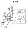
- FIG. 1 of the drawing there is shown an electroerosion machine, for example a TW-EDM machine, for machining a cantilevered workpiece 8 which is connected by a bolt clamp 11 and a support post 10 to a worktable 9 capable of being drive incrementally in two mutually perpendicular directions by motors 9 a and 9 b and respective lead screws, one of which has been shown at 9 c in FIG. 1, the motors being controlled by an NC (numerical control) unit representing any computer or programmable unit capable of generating the desired cut contour in the workpiece.
- NC numbererical control
- the tool post is represented at 2 and rises from a base 1 upon which the table 9 is movably mounted in the manner described and carries, as has been shown highly diagrammatically, a supply spool 13 of the traveling-wire electrode 3 which passes a tensioning roller 14 and between a pair of driven pinch rollers 15, 16 whose drive can be coupled to the drive of a pair of pinch rollers 25, 26 at the takeup side to maintain a predetermined tension in the wire.
- a linear stretch of the traveling wire is established between a pair of guide rollers 23, 23' and a wire is deflected into this linear stretch by a deflection roller 17.
- the wire passes through a pair of nozzle assemblies straddling the workpiece and represented at 7 and 22, respectively, at least one of these nozzle assemblies being provided with the swivel means illustrated in FIG. 2 although preferably both nozzle assemblies are provided with such swivel means (the upper nozzle assembly corresponding to FIG. 2 while the lower nozzle assembly corresponds to the structure of FIGS. 3 or 4).
- a roller 24 can serve to measure the utilization of the wire electrode and can be used as a control for the rate of feed thereof in the wire travel direction which is downwardly in FIG. 1.
- the wire 3 passes through the workpiece 8 and forms a cut therein which is in the form of a slot 8 c lying behind the wire.
- the workpiece is fed in the direction 46 which is perpendicular to the wire travel direction as previously described and, because of the kinetic energy of the machining operation released in the gap G between the machining front F and the machining surface S of the wire, there is tendency for the wire to bend away from the machining front as shown in dot-dash lines and hence for the gap width to be changed.
- the upper nozzle assembly 7 comprises a hollow base member which is formed with a passage 7 b through which the wire 3 passes into a chamber 7 c supplied, if desired with compressed air or some other fluid preventing backflow of the machining liquid into this chamber through the wire guide opening 19 of the tube 19 a traversed by the wire 3.
- the chamber 7 c receives a pair of rollers 18 and 18 a which position the wire, the roller 18 being engaged by a brush 28 in an electrically insulating sleeve 29 fitted into the base member 7.
- a bolt 32 clamps a lug 31 of a supply conductor 30 from the EDM power supply to the brush 28. The other conductor from this power supply is affixed to the clamp 11 and hence completes the electrical circuit through the workpiece 8.
- the fluid outlet member in this nozzle is represented at 35 and is formed with an inclined outlet passage 41 communicating via a chamber 21 with an inlet 45 in the hollow base member and constituting fluid inlet means for the latter.
- a coil spring 36 is braced against the base 7 and bears upon a washer 38 engaging a thrust bearing 40 lying on one side of an annular flange of the outlet member 35.
- Another thrust bearing 40 on the lower side of this flange is supported on another spring 37 so that in effect the outlet member 35 floats vertically while being biased by the dielectric fluid medium downwardly against the workpiece and being free to rotate within the base member 7.
- a caster ball 42 is provided eccentrically with respect to the axis of rotation of the member 35, bears upon the upper surface of the workpiece and preferably rides in the slot machined therein and is resiliently supported by a coil spring 43 in the axial direction.
- the diameter of the ball 42 should be greater than the width of the slot or kerf machined in the workpiece.
- the machining liquid does not flow directly axially along the wire but rather is always directed from behind against the wire and braces the wire hydraulically in the direction of the machining front F to prevent oscillation of the wire during machining operations even for large thickness workpieces and thereby improve the machining accuracy.
- the lower nozzle assembly 22 is shown and can be seen to comprise a base member 47 into which the liquid medium is fed through an inlet which has not been illustrated.
- a thrust bearing 50 rotatably supports the outlet member against the base member 47 and, of course, a spring suspension can be provided here as well, or some other floating arrangement can be utilized.
- the member 48 surrounds the tube 19 b through which the wire is fed as does the outlet member 35 of FIG. 2 and is formed with an inclined passage 49 training the liquid not strictly axially along the wire but always in the direction of the machining front as is clearly apparent from FIG. 3.
- the upper nozzle assembly has not been illustrated here but only the obstruction 19 against reverse flow of the liquid has been indicated by reference numeral.
- a diaphragm can be used for this purposes although compressed air is preferred as the reverse flow blocking medium.
- a similar blockage of reverse flow through the tube 19 B can be ensured as well.
- the caster roller is here formed by the ball 51 which is biased by a spring 53 against the lower surface of the workpiece within the recess 52 in the outlet member 48.
- the axial passage of tube 19 B has been represented at 19' in FIG. 3.
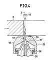
- FIG. 4 shows another lower nozzle assembly 122 in which the outlet member 56 has the inclined passage 57 and a caster ball 59 in the manner previously described, and is free to rotate via a thrust bearing 58 on the liquid supply member 55 through which the tube 19 B extends.
- the outlet from member 55 narrows before opening into the chamber 57' which is upstream of the inclined passage 57.
- the outlet member swivels to follow the progress of the cut, keeping the liquid outflow always directed against the side of the wire turned away from the machining front F.
Landscapes
- Chemical & Material Sciences (AREA)
- Chemical Kinetics & Catalysis (AREA)
- Electrochemistry (AREA)
- Engineering & Computer Science (AREA)
- Mechanical Engineering (AREA)
- Electrical Discharge Machining, Electrochemical Machining, And Combined Machining (AREA)
Priority Applications (5)
| Application Number | Priority Date | Filing Date | Title |
|---|---|---|---|
| US06/785,841 US4704511A (en) | 1985-10-17 | 1985-10-09 | Traveling-wire electroerosion machine with swiveling nozzle assembly |
| EP85307523A EP0219587B1 (de) | 1985-10-17 | 1985-10-17 | Durchlaufdraht-Elektroerosionsmaschine mit Drehdüsenanordnung |
| DE8585307523T DE3578392D1 (de) | 1985-10-17 | 1985-10-17 | Durchlaufdraht-elektroerosionsmaschine mit drehduesenanordnung. |
| SG905/90A SG90590G (en) | 1985-10-17 | 1990-11-06 | Travelling-wire electroerosion machine with swivelling nozzle assembly |
| HK1085/90A HK108590A (en) | 1985-10-17 | 1990-12-18 | Traveling-wire electroerosion machine with swiveling nozzle assembly |
Applications Claiming Priority (1)
| Application Number | Priority Date | Filing Date | Title |
|---|---|---|---|
| EP85307523A EP0219587B1 (de) | 1985-10-17 | 1985-10-17 | Durchlaufdraht-Elektroerosionsmaschine mit Drehdüsenanordnung |
Publications (2)
| Publication Number | Publication Date |
|---|---|
| EP0219587A1 true EP0219587A1 (de) | 1987-04-29 |
| EP0219587B1 EP0219587B1 (de) | 1990-06-27 |
Family
ID=8194404
Family Applications (1)
| Application Number | Title | Priority Date | Filing Date |
|---|---|---|---|
| EP85307523A Expired EP0219587B1 (de) | 1985-10-17 | 1985-10-17 | Durchlaufdraht-Elektroerosionsmaschine mit Drehdüsenanordnung |
Country Status (5)
| Country | Link |
|---|---|
| US (1) | US4704511A (de) |
| EP (1) | EP0219587B1 (de) |
| DE (1) | DE3578392D1 (de) |
| HK (1) | HK108590A (de) |
| SG (1) | SG90590G (de) |
Cited By (1)
| Publication number | Priority date | Publication date | Assignee | Title |
|---|---|---|---|---|
| WO2002026434A1 (fr) * | 2000-09-28 | 2002-04-04 | Mitsubishi Denki Kabushiki Kaisha | Machine de decharge electrique a fil |
Families Citing this family (27)
| Publication number | Priority date | Publication date | Assignee | Title |
|---|---|---|---|---|
| CH670061A5 (de) * | 1986-11-26 | 1989-05-12 | Charmilles Technologies | |
| DE3942067C2 (de) * | 1988-12-23 | 1995-03-30 | Mitsubishi Electric Corp | Drahtführungsvorrichtung für eine funkenerosive Drahtschneidemaschine |
| CH680502A5 (de) * | 1988-12-23 | 1992-09-15 | Mitsubishi Electric Corp | |
| JPH02212025A (ja) * | 1989-02-08 | 1990-08-23 | Mitsubishi Electric Corp | ワイヤ放電加工装置 |
| JP2616099B2 (ja) * | 1990-02-27 | 1997-06-04 | 三菱電機株式会社 | ワイヤ放電加工装置 |
| US5384443A (en) * | 1993-01-25 | 1995-01-24 | Swartzbaugh; Jim | Flush cup extenders for electrical discharge machines |
| EP1052062A1 (de) | 1999-05-03 | 2000-11-15 | Applied Materials, Inc. | Vorbehandlung eines fixierten Schleifmittels |
| CN1137796C (zh) * | 1999-08-20 | 2004-02-11 | 三菱电机株式会社 | 线切割加工装置 |
| US6979248B2 (en) | 2002-05-07 | 2005-12-27 | Applied Materials, Inc. | Conductive polishing article for electrochemical mechanical polishing |
| US7059948B2 (en) | 2000-12-22 | 2006-06-13 | Applied Materials | Articles for polishing semiconductor substrates |
| US7303462B2 (en) | 2000-02-17 | 2007-12-04 | Applied Materials, Inc. | Edge bead removal by an electro polishing process |
| US7678245B2 (en) | 2000-02-17 | 2010-03-16 | Applied Materials, Inc. | Method and apparatus for electrochemical mechanical processing |
| US7374644B2 (en) | 2000-02-17 | 2008-05-20 | Applied Materials, Inc. | Conductive polishing article for electrochemical mechanical polishing |
| US7077721B2 (en) | 2000-02-17 | 2006-07-18 | Applied Materials, Inc. | Pad assembly for electrochemical mechanical processing |
| US7303662B2 (en) | 2000-02-17 | 2007-12-04 | Applied Materials, Inc. | Contacts for electrochemical processing |
| US6991528B2 (en) | 2000-02-17 | 2006-01-31 | Applied Materials, Inc. | Conductive polishing article for electrochemical mechanical polishing |
| US6962524B2 (en) | 2000-02-17 | 2005-11-08 | Applied Materials, Inc. | Conductive polishing article for electrochemical mechanical polishing |
| US7066800B2 (en) | 2000-02-17 | 2006-06-27 | Applied Materials Inc. | Conductive polishing article for electrochemical mechanical polishing |
| US7125477B2 (en) * | 2000-02-17 | 2006-10-24 | Applied Materials, Inc. | Contacts for electrochemical processing |
| US7029365B2 (en) | 2000-02-17 | 2006-04-18 | Applied Materials Inc. | Pad assembly for electrochemical mechanical processing |
| US7670468B2 (en) | 2000-02-17 | 2010-03-02 | Applied Materials, Inc. | Contact assembly and method for electrochemical mechanical processing |
| US7344432B2 (en) | 2001-04-24 | 2008-03-18 | Applied Materials, Inc. | Conductive pad with ion exchange membrane for electrochemical mechanical polishing |
| US7137879B2 (en) | 2001-04-24 | 2006-11-21 | Applied Materials, Inc. | Conductive polishing article for electrochemical mechanical polishing |
| US7084064B2 (en) | 2004-09-14 | 2006-08-01 | Applied Materials, Inc. | Full sequence metal and barrier layer electrochemical mechanical processing |
| US7520968B2 (en) | 2004-10-05 | 2009-04-21 | Applied Materials, Inc. | Conductive pad design modification for better wafer-pad contact |
| US7427340B2 (en) | 2005-04-08 | 2008-09-23 | Applied Materials, Inc. | Conductive pad |
| US20080277383A1 (en) * | 2007-05-11 | 2008-11-13 | Michael Sandlin | Apparatus for removing debris from the cutting gap of a work piece on a wire electronic discharge machine and method therefor |
Citations (2)
| Publication number | Priority date | Publication date | Assignee | Title |
|---|---|---|---|---|
| FR2527117A1 (fr) * | 1982-05-18 | 1983-11-25 | Inoue Japax Res | Buse d'alimentation en fluide de travail pour une machine d'electro-erosion a fil de coupe |
| EP0142034A1 (de) * | 1983-10-11 | 1985-05-22 | Inoue-Japax Research Incorporated | Durchlaufdraht-Elektroerosionsmaschinen mit doppelten, schwebenden Düsenanordnungen |
Family Cites Families (11)
| Publication number | Priority date | Publication date | Assignee | Title |
|---|---|---|---|---|
| JPS5841980B2 (ja) * | 1976-02-25 | 1983-09-16 | 富士通フアナツク株式会社 | 数値制御ワイヤカツト放電加工機 |
| JPS5384296A (en) * | 1976-12-29 | 1978-07-25 | Fanuc Ltd | Working flued supplying direction control system for electrically discharging wire cutting machine |
| US4481095A (en) * | 1982-02-03 | 1984-11-06 | Inoue-Japax Research Incorporated | Apparatus for supplying a working fluid and a wire electrode to a work portion of a wire-cut electrical discharge machine |
| JPS5930626A (ja) * | 1982-08-09 | 1984-02-18 | Inoue Japax Res Inc | ワイヤカツト放電加工装置 |
| JPS58202729A (ja) * | 1982-05-18 | 1983-11-26 | Inoue Japax Res Inc | ワイヤカット放電加工用加工液噴出ノズル装置 |
| JPS58217232A (ja) * | 1982-06-11 | 1983-12-17 | Inoue Japax Res Inc | ワイヤカツト放電加工装置 |
| JPS5930625A (ja) * | 1982-08-05 | 1984-02-18 | Tanaka Kikinzoku Kogyo Kk | ワイヤ−カツト放電加工機の放電液噴出器 |
| JPS5988221A (ja) * | 1982-11-08 | 1984-05-22 | Inoue Japax Res Inc | ワイヤカツト放電加工装置 |
| JPS59175927A (ja) * | 1983-03-18 | 1984-10-05 | Inoue Japax Res Inc | ワイヤカツト放電加工に於ける加工液供給装置 |
| US4575603A (en) * | 1983-03-12 | 1986-03-11 | Inoue-Japax Research Incorporated | TW-Electroerosion with controlled flushing flow guidance means |
| US4608143A (en) * | 1983-10-18 | 1986-08-26 | Inoue-Japax Research Incorporated | TW-electroerosion apparatus with wheeled drive carriages |
-
1985
- 1985-10-09 US US06/785,841 patent/US4704511A/en not_active Expired - Lifetime
- 1985-10-17 DE DE8585307523T patent/DE3578392D1/de not_active Expired - Lifetime
- 1985-10-17 EP EP85307523A patent/EP0219587B1/de not_active Expired
-
1990
- 1990-11-06 SG SG905/90A patent/SG90590G/en unknown
- 1990-12-18 HK HK1085/90A patent/HK108590A/en not_active IP Right Cessation
Patent Citations (2)
| Publication number | Priority date | Publication date | Assignee | Title |
|---|---|---|---|---|
| FR2527117A1 (fr) * | 1982-05-18 | 1983-11-25 | Inoue Japax Res | Buse d'alimentation en fluide de travail pour une machine d'electro-erosion a fil de coupe |
| EP0142034A1 (de) * | 1983-10-11 | 1985-05-22 | Inoue-Japax Research Incorporated | Durchlaufdraht-Elektroerosionsmaschinen mit doppelten, schwebenden Düsenanordnungen |
Cited By (3)
| Publication number | Priority date | Publication date | Assignee | Title |
|---|---|---|---|---|
| WO2002026434A1 (fr) * | 2000-09-28 | 2002-04-04 | Mitsubishi Denki Kabushiki Kaisha | Machine de decharge electrique a fil |
| US6815630B1 (en) | 2000-09-28 | 2004-11-09 | Mitsubishi Denki Kabushiki Kaisha | Wire electric discharge machine |
| DE10085489B4 (de) * | 2000-09-28 | 2013-05-29 | Mitsubishi Denki K.K. | Funkenerosive Drahtschneidemaschine |
Also Published As
| Publication number | Publication date |
|---|---|
| DE3578392D1 (de) | 1990-08-02 |
| EP0219587B1 (de) | 1990-06-27 |
| US4704511A (en) | 1987-11-03 |
| SG90590G (en) | 1990-12-21 |
| HK108590A (en) | 1990-12-28 |
Similar Documents
| Publication | Publication Date | Title |
|---|---|---|
| US4704511A (en) | Traveling-wire electroerosion machine with swiveling nozzle assembly | |
| US4414456A (en) | Electroerosive wire-cutting method and apparatus with a shaped high-velocity stream of a cutting liquid medium | |
| US4539459A (en) | Nozzle and power-feed element for wire-cut electrical discharge machine | |
| EP0142034B1 (de) | Durchlaufdraht-Elektroerosionsmaschinen mit doppelten, schwebenden Düsenanordnungen | |
| US4575603A (en) | TW-Electroerosion with controlled flushing flow guidance means | |
| US4605834A (en) | Precision TW electroerosion with staggering multiple V-notched guides | |
| US4629854A (en) | TW-electroerosion with means for regulating flushing liquid in cutting slot | |
| EP0130758B1 (de) | Genaues elektroerosives Bearbeiten mit Durchlaufelektrodendraht und mehreren übereinanderliegenden Führungsöffnungen | |
| US4725706A (en) | Tw-electroerosion utilizing cyclically reduced cutting feed rate | |
| WO1987000102A1 (fr) | Machine d'usinage par etincelage a fil de coupe | |
| EP0137384B1 (de) | System zum Erregen des Bearbeitungsspaltes für Durchlaufdraht-Elektroerosion | |
| US4479045A (en) | Traveling-wire electroerosive cutting method and apparatus | |
| JP2671663B2 (ja) | ワイヤ放電加工装置 | |
| US4510366A (en) | Fluid delivery rate control TW electrical machining method and apparatus | |
| US9199255B2 (en) | Variable length flush nozzles for wire electrical discharge machines | |
| US4607149A (en) | Fluid delivery rate control tw electrical machining method and apparatus | |
| US4513192A (en) | TW-EDM Method and apparatus with excess fluid stripping gas jet nozzle | |
| US4629856A (en) | Traveling-wire backing support EDM method and apparatus | |
| US4629855A (en) | Electroerosive cutting method and apparatus with a bar-supported electrode tape | |
| US4608143A (en) | TW-electroerosion apparatus with wheeled drive carriages | |
| JPS59166426A (ja) | ワイヤカツト放電加工用ノズル装置 | |
| EP0163359A2 (de) | Präzisions-Schneiddrahtelektroerosionsgerät mit mehreren versetzt angeordneten V-förmigen Nutführungen | |
| EP0180195A2 (de) | Drahtelektrodenentladungsbearbeitungsgerät | |
| JPS6029236A (ja) | ワイヤカット放電加工に於けるワイヤ電極ガイド装置 | |
| JPS62287931A (ja) | ワイヤカツト放電加工装置 |
Legal Events
| Date | Code | Title | Description |
|---|---|---|---|
| PUAI | Public reference made under article 153(3) epc to a published international application that has entered the european phase |
Free format text: ORIGINAL CODE: 0009012 |
|
| AK | Designated contracting states |
Kind code of ref document: A1 Designated state(s): DE FR GB IT |
|
| 17P | Request for examination filed |
Effective date: 19870624 |
|
| 17Q | First examination report despatched |
Effective date: 19890203 |
|
| ITF | It: translation for a ep patent filed | ||
| GRAA | (expected) grant |
Free format text: ORIGINAL CODE: 0009210 |
|
| RAP1 | Party data changed (applicant data changed or rights of an application transferred) |
Owner name: INOUE JAPAX RESEARCH INCORPORATED |
|
| AK | Designated contracting states |
Kind code of ref document: B1 Designated state(s): DE FR GB IT |
|
| REF | Corresponds to: |
Ref document number: 3578392 Country of ref document: DE Date of ref document: 19900802 |
|
| ET | Fr: translation filed | ||
| PLBE | No opposition filed within time limit |
Free format text: ORIGINAL CODE: 0009261 |
|
| STAA | Information on the status of an ep patent application or granted ep patent |
Free format text: STATUS: NO OPPOSITION FILED WITHIN TIME LIMIT |
|
| 26N | No opposition filed | ||
| ITTA | It: last paid annual fee | ||
| PGFP | Annual fee paid to national office [announced via postgrant information from national office to epo] |
Ref country code: FR Payment date: 19981013 Year of fee payment: 14 |
|
| PGFP | Annual fee paid to national office [announced via postgrant information from national office to epo] |
Ref country code: DE Payment date: 19981230 Year of fee payment: 14 |
|
| PG25 | Lapsed in a contracting state [announced via postgrant information from national office to epo] |
Ref country code: FR Free format text: LAPSE BECAUSE OF NON-PAYMENT OF DUE FEES Effective date: 20000630 |
|
| PG25 | Lapsed in a contracting state [announced via postgrant information from national office to epo] |
Ref country code: DE Free format text: LAPSE BECAUSE OF NON-PAYMENT OF DUE FEES Effective date: 20000801 |
|
| REG | Reference to a national code |
Ref country code: FR Ref legal event code: ST |
|
| PGFP | Annual fee paid to national office [announced via postgrant information from national office to epo] |
Ref country code: GB Payment date: 20001011 Year of fee payment: 16 |
|
| PG25 | Lapsed in a contracting state [announced via postgrant information from national office to epo] |
Ref country code: GB Free format text: LAPSE BECAUSE OF NON-PAYMENT OF DUE FEES Effective date: 20011017 |
|
| REG | Reference to a national code |
Ref country code: GB Ref legal event code: IF02 |
|
| GBPC | Gb: european patent ceased through non-payment of renewal fee |
Effective date: 20011017 |