EP0219669A1 - Soupape de mesure pour doser les fluides ou les gaz - Google Patents
Soupape de mesure pour doser les fluides ou les gaz Download PDFInfo
- Publication number
- EP0219669A1 EP0219669A1 EP86112343A EP86112343A EP0219669A1 EP 0219669 A1 EP0219669 A1 EP 0219669A1 EP 86112343 A EP86112343 A EP 86112343A EP 86112343 A EP86112343 A EP 86112343A EP 0219669 A1 EP0219669 A1 EP 0219669A1
- Authority
- EP
- European Patent Office
- Prior art keywords
- valve
- yoke
- metering
- piezo stack
- valve according
- Prior art date
- Legal status (The legal status is an assumption and is not a legal conclusion. Google has not performed a legal analysis and makes no representation as to the accuracy of the status listed.)
- Granted
Links
- 239000007789 gas Substances 0.000 title claims abstract description 7
- 239000012530 fluid Substances 0.000 title 1
- 238000002347 injection Methods 0.000 claims abstract description 28
- 239000007924 injection Substances 0.000 claims abstract description 28
- 239000000446 fuel Substances 0.000 claims abstract description 13
- 238000002485 combustion reaction Methods 0.000 claims abstract description 6
- 239000007788 liquid Substances 0.000 claims abstract description 6
- 230000005284 excitation Effects 0.000 claims description 20
- 230000008859 change Effects 0.000 claims description 5
- 230000009471 action Effects 0.000 claims description 4
- 230000006835 compression Effects 0.000 claims description 4
- 238000007906 compression Methods 0.000 claims description 4
- 230000003068 static effect Effects 0.000 claims description 4
- 230000004323 axial length Effects 0.000 claims description 3
- 230000001154 acute effect Effects 0.000 claims description 2
- 230000000903 blocking effect Effects 0.000 claims 1
- 230000008602 contraction Effects 0.000 abstract description 3
- 230000000694 effects Effects 0.000 abstract description 3
- 238000013016 damping Methods 0.000 description 17
- 238000004519 manufacturing process Methods 0.000 description 5
- 238000006073 displacement reaction Methods 0.000 description 4
- 230000008901 benefit Effects 0.000 description 3
- 238000010276 construction Methods 0.000 description 3
- 238000005507 spraying Methods 0.000 description 2
- 230000003213 activating effect Effects 0.000 description 1
- 238000006243 chemical reaction Methods 0.000 description 1
- 230000001419 dependent effect Effects 0.000 description 1
- 238000011161 development Methods 0.000 description 1
- 230000018109 developmental process Effects 0.000 description 1
- 230000010354 integration Effects 0.000 description 1
- 238000000034 method Methods 0.000 description 1
- 230000005012 migration Effects 0.000 description 1
- 238000013508 migration Methods 0.000 description 1
- 230000008569 process Effects 0.000 description 1
- 230000009467 reduction Effects 0.000 description 1
Images

Classifications
-
- F—MECHANICAL ENGINEERING; LIGHTING; HEATING; WEAPONS; BLASTING
- F02—COMBUSTION ENGINES; HOT-GAS OR COMBUSTION-PRODUCT ENGINE PLANTS
- F02M—SUPPLYING COMBUSTION ENGINES IN GENERAL WITH COMBUSTIBLE MIXTURES OR CONSTITUENTS THEREOF
- F02M21/00—Apparatus for supplying engines with non-liquid fuels, e.g. gaseous fuels stored in liquid form
- F02M21/02—Apparatus for supplying engines with non-liquid fuels, e.g. gaseous fuels stored in liquid form for gaseous fuels
- F02M21/0218—Details on the gaseous fuel supply system, e.g. tanks, valves, pipes, pumps, rails, injectors or mixers
- F02M21/0248—Injectors
- F02M21/0257—Details of the valve closing elements, e.g. valve seats, stems or arrangement of flow passages
- F02M21/026—Lift valves, i.e. stem operated valves
- F02M21/0269—Outwardly opening valves, e.g. poppet valves
-
- B—PERFORMING OPERATIONS; TRANSPORTING
- B05—SPRAYING OR ATOMISING IN GENERAL; APPLYING FLUENT MATERIALS TO SURFACES, IN GENERAL
- B05B—SPRAYING APPARATUS; ATOMISING APPARATUS; NOZZLES
- B05B1/00—Nozzles, spray heads or other outlets, with or without auxiliary devices such as valves, heating means
- B05B1/30—Nozzles, spray heads or other outlets, with or without auxiliary devices such as valves, heating means designed to control volume of flow, e.g. with adjustable passages
- B05B1/3033—Nozzles, spray heads or other outlets, with or without auxiliary devices such as valves, heating means designed to control volume of flow, e.g. with adjustable passages the control being effected by relative coaxial longitudinal movement of the controlling element and the spray head
- B05B1/3073—Nozzles, spray heads or other outlets, with or without auxiliary devices such as valves, heating means designed to control volume of flow, e.g. with adjustable passages the control being effected by relative coaxial longitudinal movement of the controlling element and the spray head the controlling element being a deflector acting as a valve in co-operation with the outlet orifice
-
- F—MECHANICAL ENGINEERING; LIGHTING; HEATING; WEAPONS; BLASTING
- F02—COMBUSTION ENGINES; HOT-GAS OR COMBUSTION-PRODUCT ENGINE PLANTS
- F02M—SUPPLYING COMBUSTION ENGINES IN GENERAL WITH COMBUSTIBLE MIXTURES OR CONSTITUENTS THEREOF
- F02M21/00—Apparatus for supplying engines with non-liquid fuels, e.g. gaseous fuels stored in liquid form
- F02M21/02—Apparatus for supplying engines with non-liquid fuels, e.g. gaseous fuels stored in liquid form for gaseous fuels
- F02M21/0218—Details on the gaseous fuel supply system, e.g. tanks, valves, pipes, pumps, rails, injectors or mixers
- F02M21/0248—Injectors
- F02M21/0251—Details of actuators therefor
- F02M21/0254—Electric actuators, e.g. solenoid or piezoelectric
-
- F—MECHANICAL ENGINEERING; LIGHTING; HEATING; WEAPONS; BLASTING
- F02—COMBUSTION ENGINES; HOT-GAS OR COMBUSTION-PRODUCT ENGINE PLANTS
- F02M—SUPPLYING COMBUSTION ENGINES IN GENERAL WITH COMBUSTIBLE MIXTURES OR CONSTITUENTS THEREOF
- F02M51/00—Fuel-injection apparatus characterised by being operated electrically
- F02M51/06—Injectors peculiar thereto with means directly operating the valve needle
- F02M51/0603—Injectors peculiar thereto with means directly operating the valve needle using piezoelectric or magnetostrictive operating means
-
- F—MECHANICAL ENGINEERING; LIGHTING; HEATING; WEAPONS; BLASTING
- F02—COMBUSTION ENGINES; HOT-GAS OR COMBUSTION-PRODUCT ENGINE PLANTS
- F02M—SUPPLYING COMBUSTION ENGINES IN GENERAL WITH COMBUSTIBLE MIXTURES OR CONSTITUENTS THEREOF
- F02M51/00—Fuel-injection apparatus characterised by being operated electrically
- F02M51/06—Injectors peculiar thereto with means directly operating the valve needle
- F02M51/061—Injectors peculiar thereto with means directly operating the valve needle using electromagnetic operating means
-
- F—MECHANICAL ENGINEERING; LIGHTING; HEATING; WEAPONS; BLASTING
- F02—COMBUSTION ENGINES; HOT-GAS OR COMBUSTION-PRODUCT ENGINE PLANTS
- F02M—SUPPLYING COMBUSTION ENGINES IN GENERAL WITH COMBUSTIBLE MIXTURES OR CONSTITUENTS THEREOF
- F02M61/00—Fuel-injectors not provided for in groups F02M39/00 - F02M57/00 or F02M67/00
- F02M61/16—Details not provided for in, or of interest apart from, the apparatus of groups F02M61/02 - F02M61/14
- F02M61/167—Means for compensating clearance or thermal expansion
-
- F—MECHANICAL ENGINEERING; LIGHTING; HEATING; WEAPONS; BLASTING
- F02—COMBUSTION ENGINES; HOT-GAS OR COMBUSTION-PRODUCT ENGINE PLANTS
- F02B—INTERNAL-COMBUSTION PISTON ENGINES; COMBUSTION ENGINES IN GENERAL
- F02B2275/00—Other engines, components or details, not provided for in other groups of this subclass
- F02B2275/14—Direct injection into combustion chamber
-
- F—MECHANICAL ENGINEERING; LIGHTING; HEATING; WEAPONS; BLASTING
- F02—COMBUSTION ENGINES; HOT-GAS OR COMBUSTION-PRODUCT ENGINE PLANTS
- F02B—INTERNAL-COMBUSTION PISTON ENGINES; COMBUSTION ENGINES IN GENERAL
- F02B3/00—Engines characterised by air compression and subsequent fuel addition
- F02B3/06—Engines characterised by air compression and subsequent fuel addition with compression ignition
-
- F—MECHANICAL ENGINEERING; LIGHTING; HEATING; WEAPONS; BLASTING
- F02—COMBUSTION ENGINES; HOT-GAS OR COMBUSTION-PRODUCT ENGINE PLANTS
- F02M—SUPPLYING COMBUSTION ENGINES IN GENERAL WITH COMBUSTIBLE MIXTURES OR CONSTITUENTS THEREOF
- F02M61/00—Fuel-injectors not provided for in groups F02M39/00 - F02M57/00 or F02M67/00
- F02M61/04—Fuel-injectors not provided for in groups F02M39/00 - F02M57/00 or F02M67/00 having valves, e.g. having a plurality of valves in series
- F02M61/08—Fuel-injectors not provided for in groups F02M39/00 - F02M57/00 or F02M67/00 having valves, e.g. having a plurality of valves in series the valves opening in direction of fuel flow
-
- Y—GENERAL TAGGING OF NEW TECHNOLOGICAL DEVELOPMENTS; GENERAL TAGGING OF CROSS-SECTIONAL TECHNOLOGIES SPANNING OVER SEVERAL SECTIONS OF THE IPC; TECHNICAL SUBJECTS COVERED BY FORMER USPC CROSS-REFERENCE ART COLLECTIONS [XRACs] AND DIGESTS
- Y02—TECHNOLOGIES OR APPLICATIONS FOR MITIGATION OR ADAPTATION AGAINST CLIMATE CHANGE
- Y02T—CLIMATE CHANGE MITIGATION TECHNOLOGIES RELATED TO TRANSPORTATION
- Y02T10/00—Road transport of goods or passengers
- Y02T10/10—Internal combustion engine [ICE] based vehicles
- Y02T10/12—Improving ICE efficiencies
-
- Y—GENERAL TAGGING OF NEW TECHNOLOGICAL DEVELOPMENTS; GENERAL TAGGING OF CROSS-SECTIONAL TECHNOLOGIES SPANNING OVER SEVERAL SECTIONS OF THE IPC; TECHNICAL SUBJECTS COVERED BY FORMER USPC CROSS-REFERENCE ART COLLECTIONS [XRACs] AND DIGESTS
- Y02—TECHNOLOGIES OR APPLICATIONS FOR MITIGATION OR ADAPTATION AGAINST CLIMATE CHANGE
- Y02T—CLIMATE CHANGE MITIGATION TECHNOLOGIES RELATED TO TRANSPORTATION
- Y02T10/00—Road transport of goods or passengers
- Y02T10/10—Internal combustion engine [ICE] based vehicles
- Y02T10/30—Use of alternative fuels, e.g. biofuels
Definitions
- the invention relates to a metering valve for metering liquids or gases, in particular an injection valve for fuel injection systems in internal combustion engines, such as direct injection diesel engines and the like, according to the preamble of claim 1.
- the abutment is designed as a damping piston which is arranged in a fuel-filled damping cylinder.
- the damping cylinder is connected to the fuel supply via a hole.
- the damping piston is applied to the piezostack by the valve closing spring lying in the damping cylinder, which in turn thereby pushes the valve needle onto the valve surrounding the injection opening presses on the seat, which in turn blocks the injection opening. If a control voltage is applied to the piezoelectric actuator, the piezo stack contracts and shortens its length by, for example, 30 ⁇ m.
- the mass of the damping piston and the damping effect of the fuel in the damping cylinder have the effect that the abutment is largely stationary for the moment of the piezo stack contraction and the contraction of the piezo stack does not trigger any displacement of the damping piston by the valve closing spring.
- the entire change in length of the piezo stack is converted into a lifting movement of the valve needle, so that the relatively small actuating path of the piezo stack is fully utilized for opening the injection valve.
- the metering valve according to the invention for metering liquids or gases with the characterizing features of claim 1 has the advantage that by the tolerance-free definition of the housing-side support for the piezo stack always the full length extension of the piezo stack is implemented in a stroke of the valve needle, so always the same metering cross-section released and thus an extremely precise dosage is maintained. It does not matter whether the piezoelectric actuator generates the actuating path by lengthening or reducing the length of the piezo stack. The metering accuracy can be reproduced as desired, the metering quantity for a given metering pressure being dependent solely on the duration of the valve opening.
- the electromagnetic locking device also has a small construction volume and can therefore be easily integrated into the valve housing of a small-volume metering valve.
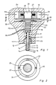
- the injection valve for fuel injection systems in internal combustion engines shown in longitudinal section in FIG. 1 as an example of a metering valve for metering liquids or gases
- the essential variables such as injection quantity, injection rate, start of injection and end of injection can be determined electrically.
- the injection valve has a valve housing 10 shown in sections, in which a stepped bore 11 with bore sections graduated in diameter is made.
- a valve body 12 with an axial through bore 13 is inserted in the lower bore section 111 on the combustion chamber side.
- the through hole 13 opens into a metering or valve opening 14 which is surrounded by a valve seat 15 in an annular manner.
- valve closing spring 17 is supported on the one hand on the valve body 12 and on the other hand on an annular flange 18 which is rigidly connected to the end of the valve needle 16 remote from the needle head 161.
- annular space 19 is present in the through bore 13, which is connected to a fuel inlet 21 via an inlet bore 20.
- a reservoir is expediently switched on between the inlet bore 20 and the fuel inlet 21.
- the central bore section 112 can serve as such a store.
- the piezo stack 22 increases its axial length in a known manner, the change in length typically being approximately 30 ⁇ m.
- An annular excitation coil 27 is held in the yoke 26.
- the armature 25, the yoke 26 and the excitation coil 27 form an electromagnetic locking device 28, with which the piezo stack 22 moves during its change in length caused by the control voltage Lich the valve body 1O is spatially determined.
- the piezo stack 22 is fixed by activating the locking device 28 at least for the duration of the valve opening.
- the electromagnetic locking device 28 is accommodated in the third bore section 113, the yoke 26 being held between a ring shoulder 29 on the valve housing side and a support disk 30. Between the support disk 3O and a further annular shoulder 3l of the valve housing 1O, a plate spring 32 is inserted, which fixes the yoke 26 in the bore section 113.
- the yoke 26 is divided into a plurality of yoke plates 33 which are U-shaped in profile and which are supported on the armature 25 when the excitation coil 27 is occupied and thus clamp it stationary.
- the yoke 26 can also be subdivided into larger yoke segments, it being sufficient to subdivide the yoke into two semicircular ring segments. In the latter case, however, care must be taken for a slight radial movement of the yoke 26 when the yoke 26 is held between the annular shoulder 29 and the support disk 30. Such play can be ensured by appropriate dimensioning of the plate spring 32.
- the control of the electromagnetic locking device 28 is such that the excitation coil 27 is constantly supplied with excitation current and is de-energized briefly only after the end of injection, that is to say after the valve opening 14 has been closed again.
- the locking device 28 is effective and the armature 25 can move axially in the yoke 26. This compensates for temperature-related changes in length of the piezo stack 22 as well as manufacturing tolerances or wear.
- the piezo stack 22 is fixed on the housing side, so that the constant adjustment path provided by the piezo stack 22 can be fully utilized for the valve needle stroke.
- the longitudinal section of the injection valve shown in FIG. 3 differs from the injection valve shown in FIG. 1 only in that the electromagnetic locking device 28 ′ is designed differently, so that components in FIG. 1 that correspond to components in FIG. but are marked with a comma to distinguish them.
- the piezo stack 22 ' is in turn directly connected to the valve needle 15' on one end face 21 'and carries an anchor plate 34' with an enlarged diameter on its other end face.
- the valve closing spring 17 ' is arranged here between the armature plate 34' and a support 35 'on the housing side and, in the same way, causes the needle head 161' of the valve needle 16 'to be pressed onto the valve seat 15' surrounding the valve opening 14 '.
- the yoke 26 'of the electromagnetic locking device 28' is horseshoe-shaped here and carries the ring-shaped excitation coil 27 'on its web 263' which integrally connects the two legs 261 'and 262'.
- the legs 261 'and 262' are arranged at right angles to the anchor plate 34 '. Their end faces 36 'and 37' run at an acute angle of inclination ⁇ to the anchor plate 34 '. Between the anchor plate 34 'and the yoke legs 261' and 262 ' a wedge element 38 'or 39' is arranged. Each wedge element 38 'or 39' has two wedge surfaces, of which a wedge surface runs parallel to the anchor plate 34 'and a wedge surface runs parallel to the end surface 36' or 37 'of the yoke legs 261' or 262 '.
- each wedge element 38 'or 39' rests on the one hand on the anchor plate 34 'and on the other hand on the end face 36' or 37 'of the yoke legs 261' or 262 '.
- a compression spring 40 ' is arranged between the two wedge elements 38' and 39 ', the direction of action of which extends parallel to the anchor plate 34'.
- the angle of inclination ⁇ of the end faces 36 ', 37' of the yoke legs 261 ', 262' and thus the wedge angle of the wedge elements 38 ', 39' is selected to be greater than the static friction angle ⁇ . The more the angle of inclination ⁇ is approximated to the static friction angle ⁇ , the smaller can the electromagnet formed by yoke 26 'and excitation coil 27'.
- the control of the excitation coil 27 ' is such that it is de-energized from shortly after the end of spraying until shortly before the start of spraying and is energized only for the duration of the valve opening.
- the piezo stack 22 is in turn fixed on the housing side during its excitation phase.
- the magnet is de-energized, relative movements of the one-piece valve actuation system consisting of valve needle 16 ', piezo stack 22' and armature plate 34 ', which are mainly caused by temperature-related changes in length of the piezo stack 22, are compensated for by the fact that the wedge elements 38' 39 'radially on the armature plate 34' can be moved outwards or inwards.
- manufacturing tolerances or wear in the actuation system comprising valve needle 16 ', piezo stack 22' and anchor plate 34 'as well as in wedge elements 38', 39 'and yoke 26' are compensated for. Manufacturing tolerances when fastening the yoke 26 'in the bore section 113' are also compensated for.
- the advantage of the electromagnetic locking device 28 ′ shown in FIG. 3 compared to the locking device 28 shown in FIG. 1 is that the reaction forces of the piezo stack 22 can be absorbed with a much smaller electromagnet.
Landscapes
- Engineering & Computer Science (AREA)
- Chemical & Material Sciences (AREA)
- Combustion & Propulsion (AREA)
- Mechanical Engineering (AREA)
- General Engineering & Computer Science (AREA)
- Oil, Petroleum & Natural Gas (AREA)
- Chemical Kinetics & Catalysis (AREA)
- General Chemical & Material Sciences (AREA)
- Analytical Chemistry (AREA)
- Electromagnetism (AREA)
- Physics & Mathematics (AREA)
- Fuel-Injection Apparatus (AREA)
- Nozzles (AREA)
Applications Claiming Priority (2)
| Application Number | Priority Date | Filing Date | Title |
|---|---|---|---|
| DE3533975 | 1985-09-24 | ||
| DE19853533975 DE3533975A1 (de) | 1985-09-24 | 1985-09-24 | Zumessventil zur dosierung von fluessigkeiten oder gasen |
Publications (2)
| Publication Number | Publication Date |
|---|---|
| EP0219669A1 true EP0219669A1 (fr) | 1987-04-29 |
| EP0219669B1 EP0219669B1 (fr) | 1988-12-07 |
Family
ID=6281763
Family Applications (1)
| Application Number | Title | Priority Date | Filing Date |
|---|---|---|---|
| EP86112343A Expired EP0219669B1 (fr) | 1985-09-24 | 1986-09-06 | Soupape de mesure pour doser les fluides ou les gaz |
Country Status (4)
| Country | Link |
|---|---|
| US (1) | US4750706A (fr) |
| EP (1) | EP0219669B1 (fr) |
| JP (1) | JPH0745857B2 (fr) |
| DE (2) | DE3533975A1 (fr) |
Families Citing this family (66)
| Publication number | Priority date | Publication date | Assignee | Title |
|---|---|---|---|---|
| JPH01187363A (ja) * | 1988-01-21 | 1989-07-26 | Toyota Motor Corp | 内燃機関用燃料噴射弁 |
| DE3833093A1 (de) * | 1988-09-29 | 1990-04-12 | Siemens Ag | Fuer verbrennungskraftmaschine vorgesehene kraftstoff-einspritzduese mit steuerbarer charakteristik des kraftstoffstrahls |
| DE69022977T2 (de) * | 1989-01-11 | 1996-03-14 | Oras Oy | Regelungsventil für leitung und verwendung bei einem ultraschallmotor. |
| JPH0486367A (ja) * | 1990-07-30 | 1992-03-18 | Aisin Seiki Co Ltd | 燃料噴射弁 |
| ES2125330T5 (es) † | 1992-02-17 | 2003-02-16 | Orbital Eng Pty | Toberas inyectoras. |
| US5271226A (en) * | 1992-04-24 | 1993-12-21 | The United States Of America, As Represented By The Secretary Of Commerce | High speed, amplitude variable thrust control |
| US5417142A (en) * | 1992-12-18 | 1995-05-23 | Caterpillar Inc. | Hydraulic amplifier |
| DE4325904C2 (de) * | 1993-08-02 | 1995-07-20 | Daimler Benz Ag | Für eine Dieselbrennkraftmaschine vorgesehene Kraftstoffeinspritzanlage mit einer den Kraftstoff fördernden Hochdruckpumpe in eine gemeinsame Versorgungsleitung (Common-Rail) für alle Einspritzdüsen |
| FR2726603B1 (fr) * | 1994-11-09 | 1996-12-13 | Snecma | Dispositif de controle actif des instabilites de combustion et de decokefaction d'un injecteur de carburant |
| US5645226A (en) * | 1995-02-13 | 1997-07-08 | Siemens Automotive Corporation | Solenoid motion initiator |
| AT1622U1 (de) * | 1995-02-28 | 1997-08-25 | Avl Verbrennungskraft Messtech | Einspritzsystem mit einem einspritzventil für eine selbstzündende brennkraftmaschine |
| GB2303403A (en) * | 1995-07-13 | 1997-02-19 | Ricardo Consulting Eng | Fuel injector with piezo-electric element to vary the size or shape of the ou t passage |
| DE19531652A1 (de) * | 1995-08-29 | 1997-05-07 | Bosch Gmbh Robert | Kraftstoffeinspritzventil für Brennkraftmaschinen |
| DE19534445C2 (de) * | 1995-09-16 | 1998-07-30 | Man Nutzfahrzeuge Ag | Einspritzventil für Brennkraftmaschinen |
| US6026847A (en) * | 1995-10-11 | 2000-02-22 | Reinicke; Robert H. | Magnetostrictively actuated valve |
| US5868375A (en) * | 1995-10-11 | 1999-02-09 | Marotta Scientific Controls, Inc. | Magnetostrictively actuated valve |
| DE19621796A1 (de) * | 1996-05-30 | 1997-12-04 | Nass Magnet Gmbh | Ventil |
| DE19624936A1 (de) * | 1996-06-21 | 1998-01-08 | Focke & Co | Düsenaggregat zum Auftragen von Leim |
| DE19701288C2 (de) * | 1997-01-16 | 1999-10-14 | Daimler Benz Ag | Ventil zur dosierten Abgabe von Fluiden |
| US6091314A (en) * | 1998-06-05 | 2000-07-18 | Siemens Automotive Corporation | Piezoelectric booster for an electromagnetic actuator |
| DE19844837B4 (de) * | 1998-09-30 | 2009-05-07 | Robert Bosch Gmbh | Kraftstoffeinspritzventil für Brennkraftmaschinen |
| DE19848950C2 (de) * | 1998-10-23 | 2003-03-06 | Daimler Chrysler Ag | Vorrichtung zur Konstantsteuerung piezoelektrischer Aktuatoren für Kraftstoffeinspritzsysteme |
| DE19854508C1 (de) * | 1998-11-25 | 2000-05-11 | Siemens Ag | Dosiervorrichtung |
| DE19905340C2 (de) * | 1999-02-09 | 2001-09-13 | Siemens Ag | Verfahren und Anordnung zur Voreinstellung und dynamischen Nachführung piezoelektrischer Aktoren |
| DE19905413A1 (de) | 1999-02-10 | 2000-08-24 | Bosch Gmbh Robert | Injektor mit Piezo-Mehrlagenaktor für Einspritzsysteme |
| DE19906467A1 (de) * | 1999-02-16 | 2000-08-24 | Bosch Gmbh Robert | Injektor mit einem Piezo-Mehrlagenaktor |
| DE19912665A1 (de) * | 1999-03-20 | 2000-09-21 | Bosch Gmbh Robert | Brennstoffeinspritzventil |
| DE19918976A1 (de) * | 1999-04-27 | 2000-11-02 | Bosch Gmbh Robert | Brennstoffeinspritzventil und Verfahren zu dessen Betätigung |
| DE19921489A1 (de) * | 1999-05-08 | 2000-11-09 | Bosch Gmbh Robert | Brennstoffeinspritzventil |
| DE19946841A1 (de) * | 1999-09-30 | 2001-05-03 | Bosch Gmbh Robert | Ventil zum Steuern von Flüssigkeiten |
| US6575138B2 (en) * | 1999-10-15 | 2003-06-10 | Westport Research Inc. | Directly actuated injection valve |
| US6836056B2 (en) | 2000-02-04 | 2004-12-28 | Viking Technologies, L.C. | Linear motor having piezo actuators |
| US6437226B2 (en) | 2000-03-07 | 2002-08-20 | Viking Technologies, Inc. | Method and system for automatically tuning a stringed instrument |
| US6548938B2 (en) * | 2000-04-18 | 2003-04-15 | Viking Technologies, L.C. | Apparatus having a pair of opposing surfaces driven by a piezoelectric actuator |
| US6717332B2 (en) | 2000-04-18 | 2004-04-06 | Viking Technologies, L.C. | Apparatus having a support structure and actuator |
| US6568602B1 (en) | 2000-05-23 | 2003-05-27 | Caterpillar Inc | Variable check stop for micrometering in a fuel injector |
| US6363913B1 (en) * | 2000-06-09 | 2002-04-02 | Caterpillar Inc. | Solid state lift for micrometering in a fuel injector |
| US6345771B1 (en) | 2000-06-30 | 2002-02-12 | Siemens Automotive Corporation | Multiple stack piezoelectric actuator for a fuel injector |
| US6400066B1 (en) | 2000-06-30 | 2002-06-04 | Siemens Automotive Corporation | Electronic compensator for a piezoelectric actuator |
| IT1320475B1 (it) * | 2000-06-30 | 2003-11-26 | Fiat Ricerche | Attuatore piezoelettrico autocompensato per una valvola di controllo. |
| US6739528B2 (en) | 2000-10-11 | 2004-05-25 | Siemens Automotive Corporation | Compensator assembly having a flexible diaphragm and an internal filling tube for a fuel injector and method |
| US6879087B2 (en) | 2002-02-06 | 2005-04-12 | Viking Technologies, L.C. | Apparatus for moving a pair of opposing surfaces in response to an electrical activation |
| US6759790B1 (en) | 2001-01-29 | 2004-07-06 | Viking Technologies, L.C. | Apparatus for moving folded-back arms having a pair of opposing surfaces in response to an electrical activation |
| US6499471B2 (en) | 2001-06-01 | 2002-12-31 | Siemens Automotive Corporation | Hydraulic compensator for a piezoelectrical fuel injector |
| US6766965B2 (en) | 2001-08-31 | 2004-07-27 | Siemens Automotive Corporation | Twin tube hydraulic compensator for a fuel injector |
| DE10163731A1 (de) * | 2001-12-21 | 2003-07-10 | Biochip Technologies Gmbh | Piezoaktor |
| WO2004001871A2 (fr) * | 2002-06-21 | 2003-12-31 | Viking Technologies, L.C. | Moteur piezo-electrique monobloc |
| US6811093B2 (en) * | 2002-10-17 | 2004-11-02 | Tecumseh Products Company | Piezoelectric actuated fuel injectors |
| CA2521307C (fr) | 2003-04-04 | 2014-07-15 | Viking Technologies, L.C. | Appareil et processus d'optimisation du travail a partir d'un dispositif de commande materiel intelligent |
| DE10326707B3 (de) * | 2003-06-11 | 2005-01-27 | Westport Germany Gmbh | Ventilvorrichtung und Verfahren zum Einblasen von gasförmigem Kraftstoff |
| US7744015B2 (en) * | 2006-01-23 | 2010-06-29 | Kimberly-Clark Worldwide, Inc. | Ultrasonic fuel injector |
| US8191732B2 (en) * | 2006-01-23 | 2012-06-05 | Kimberly-Clark Worldwide, Inc. | Ultrasonic waveguide pump and method of pumping liquid |
| US7819335B2 (en) * | 2006-01-23 | 2010-10-26 | Kimberly-Clark Worldwide, Inc. | Control system and method for operating an ultrasonic liquid delivery device |
| US7963458B2 (en) * | 2006-01-23 | 2011-06-21 | Kimberly-Clark Worldwide, Inc. | Ultrasonic liquid delivery device |
| US7810743B2 (en) * | 2006-01-23 | 2010-10-12 | Kimberly-Clark Worldwide, Inc. | Ultrasonic liquid delivery device |
| US7735751B2 (en) * | 2006-01-23 | 2010-06-15 | Kimberly-Clark Worldwide, Inc. | Ultrasonic liquid delivery device |
| US8028930B2 (en) * | 2006-01-23 | 2011-10-04 | Kimberly-Clark Worldwide, Inc. | Ultrasonic fuel injector |
| US7424883B2 (en) * | 2006-01-23 | 2008-09-16 | Kimberly-Clark Worldwide, Inc. | Ultrasonic fuel injector |
| FR2908835B1 (fr) * | 2006-11-22 | 2008-12-19 | Renault Sas | Injecteur de carburant pour moteur a combustion interne |
| FR2908836B1 (fr) * | 2006-11-22 | 2009-02-13 | Renault Sas | Injecteur de carburant pour moteur a combustion interne |
| FR2908834B1 (fr) * | 2006-11-22 | 2008-12-19 | Renault Sas | Injecteur de carburant pour moteur a combustion interne |
| FR2916810B1 (fr) * | 2007-05-31 | 2009-08-28 | Renault Sas | Dispositif d'injection de fluide |
| FR2918122B1 (fr) * | 2007-06-27 | 2009-08-28 | Renault Sas | Dispositif d'injection de fluide. |
| FR2929656A1 (fr) * | 2008-04-03 | 2009-10-09 | Renault Sas | Injecteur de fluide, et procede de commande d'un tel injecteur |
| US20100001094A1 (en) * | 2008-07-03 | 2010-01-07 | Caterpillar Inc. | Apparatus and method for cooling a fuel injector including a piezoelectric element |
| US20130068200A1 (en) * | 2011-09-15 | 2013-03-21 | Paul Reynolds | Injector Valve with Miniscule Actuator Displacement |
Citations (6)
| Publication number | Priority date | Publication date | Assignee | Title |
|---|---|---|---|---|
| DE1751543A1 (de) * | 1968-06-15 | 1970-08-27 | Kloeckner Humboldt Deutz Ag | Elektrisch steuerbares Einspritzventil |
| DE1809465A1 (de) * | 1968-11-18 | 1970-09-24 | Kloeckner Humboldt Deutz Ag | Elektrisch steuerbares Einspritzventil |
| DE2917933A1 (de) * | 1978-05-08 | 1979-11-15 | Philips Nv | Regelventil |
| FR2491270A1 (fr) * | 1980-10-01 | 1982-04-02 | Daimler Benz Ag | Organe d'actionnement commande electriquement |
| DE3422935A1 (de) * | 1983-06-20 | 1984-12-20 | Nippon Soken, Inc., Nishio, Aichi | Piezoelektrischer wandler |
| GB2165308A (en) * | 1984-10-09 | 1986-04-09 | Diesel Kiki Co | Fuel injection nozzle for internal combustion engines |
Family Cites Families (4)
| Publication number | Priority date | Publication date | Assignee | Title |
|---|---|---|---|---|
| DE2931874C2 (de) * | 1979-08-06 | 1983-08-04 | Audi Nsu Auto Union Ag, 7107 Neckarsulm | Elektrisch betätigbares Ventil |
| DE3039915A1 (de) * | 1980-10-23 | 1982-05-27 | Robert Bosch Gmbh, 7000 Stuttgart | Elektrisch ansteuerbare ventileinrichtung |
| JPS57136859U (fr) * | 1981-02-18 | 1982-08-26 | ||
| DE3237258C1 (de) * | 1982-10-08 | 1983-12-22 | Daimler-Benz Ag, 7000 Stuttgart | Elektrisch vorgesteuerte Ventilanordnung |
-
1985
- 1985-09-24 DE DE19853533975 patent/DE3533975A1/de not_active Withdrawn
-
1986
- 1986-07-29 US US06/893,899 patent/US4750706A/en not_active Expired - Lifetime
- 1986-09-06 EP EP86112343A patent/EP0219669B1/fr not_active Expired
- 1986-09-06 DE DE8686112343T patent/DE3661370D1/de not_active Expired
- 1986-09-24 JP JP61223959A patent/JPH0745857B2/ja not_active Expired - Lifetime
Patent Citations (6)
| Publication number | Priority date | Publication date | Assignee | Title |
|---|---|---|---|---|
| DE1751543A1 (de) * | 1968-06-15 | 1970-08-27 | Kloeckner Humboldt Deutz Ag | Elektrisch steuerbares Einspritzventil |
| DE1809465A1 (de) * | 1968-11-18 | 1970-09-24 | Kloeckner Humboldt Deutz Ag | Elektrisch steuerbares Einspritzventil |
| DE2917933A1 (de) * | 1978-05-08 | 1979-11-15 | Philips Nv | Regelventil |
| FR2491270A1 (fr) * | 1980-10-01 | 1982-04-02 | Daimler Benz Ag | Organe d'actionnement commande electriquement |
| DE3422935A1 (de) * | 1983-06-20 | 1984-12-20 | Nippon Soken, Inc., Nishio, Aichi | Piezoelektrischer wandler |
| GB2165308A (en) * | 1984-10-09 | 1986-04-09 | Diesel Kiki Co | Fuel injection nozzle for internal combustion engines |
Also Published As
| Publication number | Publication date |
|---|---|
| EP0219669B1 (fr) | 1988-12-07 |
| DE3661370D1 (en) | 1989-01-12 |
| US4750706A (en) | 1988-06-14 |
| JPS6275065A (ja) | 1987-04-06 |
| JPH0745857B2 (ja) | 1995-05-17 |
| DE3533975A1 (de) | 1987-03-26 |
Similar Documents
| Publication | Publication Date | Title |
|---|---|---|
| EP0219669B1 (fr) | Soupape de mesure pour doser les fluides ou les gaz | |
| DE2931874C2 (de) | Elektrisch betätigbares Ventil | |
| EP0218895A1 (fr) | Soupape de mesure pour doser les fluides ou les gaz | |
| DE602005002126T2 (de) | Verstellbares Dosierservoventil eines Einspritzventils | |
| DE3205654A1 (de) | Dosierventil | |
| WO1996037698A1 (fr) | Soupape d'injection | |
| EP1567765B1 (fr) | Soupape d'injection | |
| EP1474603A1 (fr) | Soupape d'injection de carburant | |
| DE19946841A1 (de) | Ventil zum Steuern von Flüssigkeiten | |
| EP1135597A1 (fr) | Soupape d'injection de carburant | |
| WO2001023744A1 (fr) | Soupape pour commander le passage de fluides | |
| EP1092089A1 (fr) | Soupape d'injection de carburant et son procede d'actionnement | |
| DE29717649U1 (de) | Direktgesteuertes Einspritzventil, insbesondere Kraftstoffeinspritzventil | |
| EP1472451B1 (fr) | Soupape d'injection de combustible | |
| WO2000060232A1 (fr) | Soupape d'injection de carburant | |
| WO2002006663A1 (fr) | Soupape d'injection de carburant | |
| DE19716226C2 (de) | Kraftstoffeinspritzventil für Brennkraftmaschinen | |
| DE3741526C2 (fr) | ||
| DE10007733A1 (de) | Einspritzventil | |
| DE10123218A1 (de) | Ventil zum Steuern von Flüssigkeiten | |
| EP3559438B1 (fr) | Injecteur de carburant et utilisation de celui-ci | |
| EP1916414A2 (fr) | Injecteur de carburant doté d'un piezoacteur | |
| EP1144847A1 (fr) | Soupape d'injection de carburant | |
| WO2008061842A1 (fr) | Injecteur de carburant | |
| EP1664525A1 (fr) | Dispositif de dosage |
Legal Events
| Date | Code | Title | Description |
|---|---|---|---|
| PUAI | Public reference made under article 153(3) epc to a published international application that has entered the european phase |
Free format text: ORIGINAL CODE: 0009012 |
|
| AK | Designated contracting states |
Kind code of ref document: A1 Designated state(s): DE FR GB |
|
| 17P | Request for examination filed |
Effective date: 19870909 |
|
| 17Q | First examination report despatched |
Effective date: 19880224 |
|
| GRAA | (expected) grant |
Free format text: ORIGINAL CODE: 0009210 |
|
| AK | Designated contracting states |
Kind code of ref document: B1 Designated state(s): DE FR GB |
|
| REF | Corresponds to: |
Ref document number: 3661370 Country of ref document: DE Date of ref document: 19890112 |
|
| GBT | Gb: translation of ep patent filed (gb section 77(6)(a)/1977) | ||
| ET | Fr: translation filed | ||
| PLBE | No opposition filed within time limit |
Free format text: ORIGINAL CODE: 0009261 |
|
| STAA | Information on the status of an ep patent application or granted ep patent |
Free format text: STATUS: NO OPPOSITION FILED WITHIN TIME LIMIT |
|
| 26N | No opposition filed | ||
| REG | Reference to a national code |
Ref country code: GB Ref legal event code: 746 |
|
| REG | Reference to a national code |
Ref country code: FR Ref legal event code: DL |
|
| PGFP | Annual fee paid to national office [announced via postgrant information from national office to epo] |
Ref country code: GB Payment date: 19980825 Year of fee payment: 13 |
|
| PGFP | Annual fee paid to national office [announced via postgrant information from national office to epo] |
Ref country code: FR Payment date: 19980925 Year of fee payment: 13 |
|
| PGFP | Annual fee paid to national office [announced via postgrant information from national office to epo] |
Ref country code: DE Payment date: 19981130 Year of fee payment: 13 |
|
| PG25 | Lapsed in a contracting state [announced via postgrant information from national office to epo] |
Ref country code: GB Free format text: LAPSE BECAUSE OF NON-PAYMENT OF DUE FEES Effective date: 19990906 |
|
| GBPC | Gb: european patent ceased through non-payment of renewal fee |
Effective date: 19990906 |
|
| PG25 | Lapsed in a contracting state [announced via postgrant information from national office to epo] |
Ref country code: FR Free format text: LAPSE BECAUSE OF NON-PAYMENT OF DUE FEES Effective date: 20000531 |
|
| PG25 | Lapsed in a contracting state [announced via postgrant information from national office to epo] |
Ref country code: DE Free format text: LAPSE BECAUSE OF NON-PAYMENT OF DUE FEES Effective date: 20000701 |
|
| REG | Reference to a national code |
Ref country code: FR Ref legal event code: ST |